B&K 1653A Variac · Volume 1
B&K 1653A Variac — Vol 1: Overview & Decision Tree
What the 1653A is, what it actually protects against, and the one decision tree every unknown chassis has to pass before the AC VOLTS knob moves off zero.
1.1 Bench Role: Why This Instrument Gates Every Tube-Era Project
The 1653A is bench infrastructure, not a project in itself. It exists to answer one question safely: what happens when line voltage first reaches a chassis that has been sitting unpowered — sometimes for decades? Every other instrument in this hub’s tube-era lineage depends on the answer coming back clean before it gets touched. The Heathkit IP-32 HV Power Supply, the Heathkit SP-2717A HVPS, and the Heathkit TT-1 Tube Tester are all themselves vintage AC-line-powered gear with their own electrolytics, their own power transformers, and their own dormancy risk — before any of them gets plugged straight into a wall outlet for the first time in this shop, it goes through the 1653A first, using the same decision tree and ramp protocol this volume and Vol 4 describe. That is the practical reason this is Vol 1 of a six-volume dive on what looks, at a glance, like a simple dial-and-meter box: the whole rest of the hub’s power-up discipline is written assuming this instrument (or an equivalent isolated, metered, fused AC source) sits between the wall and the DUT.
1.2 What “Variac” Actually Means
“Variac” is a genericized trademark. From 1934 to 2002 it belonged to General Radio Company for its line of variable autotransformers; General Radio’s Variac line (later Technipower / Tenney / etc. lineage) legally dropped the mark, and in 2004 Instrument Service Equipment, Inc. (ISE) picked it up and registered it for the same product category. In the interim it did what Xerox and Kleenex did — everybody just calls a variable autotransformer “a variac” regardless of who made it. This deep dive uses “variac” generically for the device class and “1653A” for the specific B&K Precision instrument on the bench.
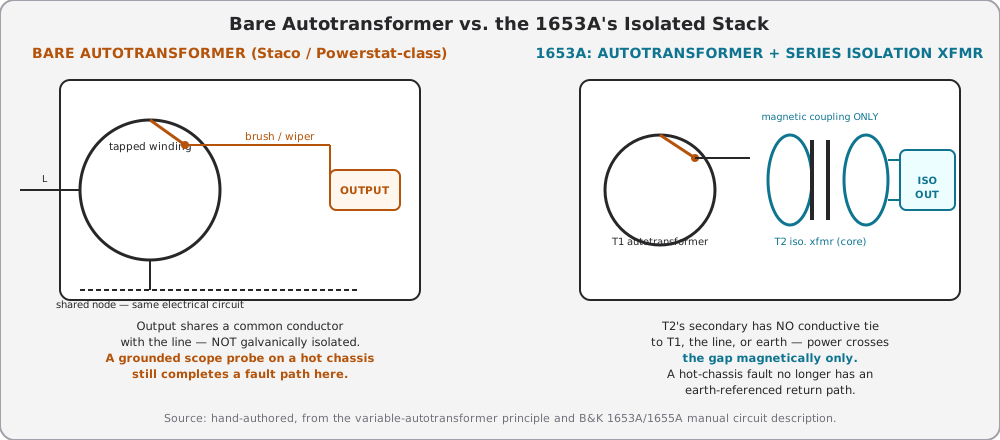
A variable autotransformer is a single winding wound on a toroidal (or occasionally rectangular) core with the insulation stripped off a strip along one face of the winding. A carbon brush rides that exposed strip and is mechanically ganged to the front-panel knob. Rotating the knob moves the brush along the winding, which changes the number of turns between the line input and the tap point the brush is sitting on. Because it’s one winding used as both primary and secondary, the “secondary” (brush) output shares a physical, current-carrying conductor with the “primary” (line) input. That shared conductor is the entire mechanism — and it is also the entire limitation:
⚠ Danger — A bare variable autotransformer provides zero galvanic isolation. Its output is not a new, floating supply — it is the same line circuit, tapped at a different point. Neutral in is neutral out (same node), and depending on which line-cord blade sits on the winding’s grounded end, the “hot” output terminal can be accidentally live even when the dial reads 0 V. Treat a bare autotransformer’s output exactly like line voltage, because electrically it still is.
Because the winding is continuous rather than split into separate primary/secondary loops, a variable autotransformer can typically run its wiper output below or above the line input voltage — the classic “buck/boost” behavior general-purpose variacs are prized for. Turns ratio between the tapped point and the full winding sets the output as a simple fraction or multiple of line voltage; a brush parked at the very end of the winding, past the line-input tap, produces a boosted output because the load now sees more turns than the line side does. The 1653A is deliberately built for its intended job: with a 120 Vac input it caps out at 0–150 Vac, a 125% boost ceiling, and nothing beyond that — enough headroom to compensate for a sagging branch circuit or to margin-test equipment above nominal line, but not enough to reach the 200%+ boost some general-purpose lab variacs offer. That ceiling is a design decision aimed at bench servicing, not a hard physical limit of the autotransformer principle in general — see Vol 2 §1 for the winding/brush theory in full, including magnetizing current, the mechanics of brush wear and wiper-track arcing at high current, and why some general-purpose variacs go both directions from a single input.
1.3 The 1653A’s Architecture in One Paragraph
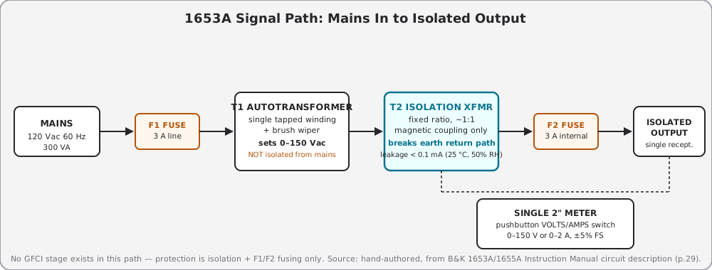
The 1653A is two transformers in series, not one. Per B&K’s own circuit description: line power feeds a variable autotransformer (T1) whose wiper, set by the front-panel AC VOLTS control, produces 0–150 Vac referenced to the line. That wiper output — still non-isolated, still line-referenced — is then applied across the primary of a second, fixed-ratio isolation transformer (T2), and T2’s secondary is what appears at the single ISOLATED OUTPUT receptacle on the front panel. T1 sets the voltage; T2 breaks the electrical tie to the building’s neutral/earth reference. Two different jobs, two different windings, in series. This is the single most important internal fact about the instrument and it is why “Variac” (bare autotransformer) and “isolated variac” (this class of instrument) are not the same tool even though they share a knob and a dial.
1.3.1 What Isolation Buys You — and What It Does Not
Note — Isolation breaks the return path. A “hot chassis” set — an AC/DC “All-American Five” radio, a transformerless TV, anything with a voltage-doubler or capacitor-input rectifier tied straight to the line — normally has its chassis sitting at up to full line potential relative to earth. Clip a grounded oscilloscope probe to that chassis on straight wall power and you’ve just tied the chassis to earth through the scope’s power cord: instant short, instant breaker trip, possibly a fried scope input or a fried chassis trace. Power that same set through the 1653A’s isolated output and the chassis is no longer earth-referenced at all — there is no conductive path back to true ground for the scope ground clip to complete. The fault current that would have flowed simply has nowhere to go.
Isolation does not make the chassis “safe to touch,” and it does not mean two isolated things are safe relative to each other. Vol 3 is the canonical treatment of this — floating-chassis physiology, the one-hand rule, and the specific way a floating secondary can defeat a downstream GFCI are all there. The short version for this overview: isolation solves an earth-loop problem, not a touch problem. You can still be the return path between two points on an isolated chassis, or between two separately-isolated hot chassis powered from two different variacs on the same bench. See Vol 3 §2–§3 before assuming isolation means “safe.”
1.4 What the 1653A Actually Adds Over a Bare Autotransformer
This is where the 1653A earns its keep against a $60–120 bare autotransformer (Staco 3PN1010B, Powerstat 116B, or an unbranded eBay unit). Per B&K’s own datasheet and instruction manual for this model:
Table 1 — This is where the 1653A earns its keep against a $60–120 bare autotransformer (Staco 3PN1010B, Powerstat 116B, or an unbranded eBay unit). Per B&K's own datasheet and instruction manual for this model
| Feature | Bare autotransformer (Staco 3PN1010B-class) | B&K 1653A |
|---|---|---|
| Output isolation | None — shared node with line | Yes — series isolation xfmr, leakage < 0.1 mA (25 °C, 50% RH) |
| Overcurrent protection | Single fuse, output side | Two fuses: F1 line input (3 A), F2 internal output (3 A) |
| Metering | None (dial position only, no V/A readout) | Single 2” dual-function analog meter, pushbutton-switched 0–150 V / 0–2 A scales, ±5% of full scale |
| Output current | ~10 A (3PN1010B) | 2 A continuous (0–130 V), derates above 130 V |
| Output voltage range | 0–140 V typical | 0–150 V |
| Output receptacles | 1, fused | 1, isolated |
| Typical role | General-purpose bench AC adjustment, motor/lamp testing | Isolated, metered, fused servicing supply for hot-chassis and reformation work |
⚠ Danger — the 1653A has no GFCI. B&K’s own 1653A/1655A datasheet and instruction manual specify only a 3 A line input fuse (F1) and a 3 A internal output fuse (F2) — no ground-fault interrupter, and no circuit breaker (a 3.15 A auto-reset circuit breaker exists only on the higher-current 1655A sibling, in place of F1). The 1653A’s entire protection story is isolation + dual fusing, full stop. There is no GFCI TEST/RESET control on this unit’s front panel — none exists in the manual’s Controls & Indicators section (Figures 1/2), and none should be assumed present.
That correction matters practically, not just editorially: a fuse is a slow, current-magnitude-triggered device with no sensitivity to a few milliamps of leakage current through a person. It protects the instrument and the wiring from overcurrent; it does not sense or interrupt a small ground-fault current the way a UL 943 Class A GFCI (4–6 mA trip threshold; trip time follows an inverse-time curve — on the order of tens of milliseconds for a substantial fault, but permissibly much longer right at the 4–6 mA threshold) would in a bathroom outlet. The 1653A’s isolation transformer is what keeps a leakage path from having anywhere to go in the first place — it is a prevention strategy, not a detection-and-trip strategy. Vol 3 §3 covers this distinction (isolation vs. GFCI as solving different problems) in full; Vol 4’s current-watch discipline exists precisely because nothing in this instrument will interrupt a fault for you — you are the fault detector, watching the ammeter.
1.4.1 GFCI vs. Isolation, in Brief
Because the correction above is easy to skim past: a GFCI is an active device — it senses a current imbalance between hot and neutral and trips a relay, typically at a 4–6 mA threshold (UL 943 Class A). The 1653A’s isolation transformer is passive — it simply removes the earth-referenced return path, so there is nothing for a downstream GFCI to sense in the first place (a floating secondary defeats a GFCI wired after it). Isolation and ground-fault interruption solve different problems, and the 1653A only does the first one. Vol 3 §3 is the canonical, fully-worked version of this comparison for the whole hub, including why a cautious bench may still want a separate GFCI outlet somewhere upstream of the 1653A’s line cord.
1.5 Sub-Categories of Variable AC Sources
Not every “variac-shaped” bench tool does the same job. Knowing which category you’re holding matters before you plug a hot-chassis radio into it.
Table 2 — Sub-Categories of Variable AC Sources
| Category | Isolation? | Metering? | Fault protection | Typical use | Example |
|---|---|---|---|---|---|
| Bare variable autotransformer | No | None or dial only | Single output fuse | General AC adjustment, motor/lamp dimming | Staco 3PN1010B, Powerstat 116B |
| Isolated variable autotransformer, unmetered | Yes | None | Fuse(s) | Budget isolated servicing supply | Various no-name eBay “isolated variac” units |
| This instrument class: isolated + metered + dual-fused | Yes | Analog V/A, ±5% FS | Line + output fuses | Bench servicing, cap reformation, brown-out testing | B&K 1653A, B&K 1655A (adds leakage meter, soldering-iron output, breaker) |
| Series-lamp current limiter (“dim bulb tester”) | No (usually built around a bare receptacle) | None (bulb brightness is the “meter”) | Self-limiting via bulb resistance | Cheap, crude current limiting alongside a separate isolation source | Shop-built lamp-in-series boxes |
| Programmable/electronic AC source | Yes (typically) | Digital, often true-RMS | Electronic current limit, programmable | Lab-grade margin and compliance testing | Chroma, Pacific Power, Keysight AC sources |
The dim-bulb tester is worth flagging here because it gets confused with a variac constantly: it is a complementary current limiter, not a substitute for isolation, and not a substitute for metering. Vol 5 §4 covers combining the 1653A with a series lamp for extra current-limit margin during reformation work.
One physical constraint worth stating plainly: the 1653A has a single standard 3-wire output receptacle (the 1655A has two). That is one DUT at a time. Never connect a second hot-chassis piece of equipment to the same isolated output through a splitter or power strip to “save an outlet” — two hot chassis riding the same isolated secondary are electrically bonded to each other through that shared output, which reintroduces exactly the kind of shock hazard between chassis that isolation was supposed to remove. If a session needs two isolated DUTs live at once, that is two separate isolated sources, not one 1653A and a splitter.
1.5.1 Sizing Context: the 1655A Sibling
The 1653A’s direct sibling in B&K’s line, the 1655A, shares the same 0–150 Vac architecture and the same “no GFCI” fact, but adds headroom and instrumentation the 1653A doesn’t have: 3 A continuous / 4 A intermittent output (vs. 2 A continuous), a dedicated power-line leakage-current meter (0–5000 µA, expanded 100–500 µA scale) with a hand probe, a resettable 3.15 A circuit breaker in place of a line fuse, dual isolated output outlets, and a built-in soldering-iron temperature control unrelated to the isolated output. None of that changes anything in this volume’s decision tree or safety story — the leakage meter is a nice-to-have for OSHA/UL/CSA-style power-line leakage testing, not a ground-fault trip device, and the 1655A’s breaker is still not a GFCI. If a future unit in this hub is a 1655A rather than a 1653A, everything in Vols 1–4 applies unchanged except the current derating numbers.
1.6 When to Reach for the 1653A — and When Not To
Table 3 — When to Reach for the 1653A — and When Not To
| Reach for the 1653A when… | Reach for something else when… |
|---|---|
| Powering up any hot-chassis / AC-DC set for the first time in years | The DUT is already known-isolated internally (has its own power transformer) and you just need adjustable AC — a bare autotransformer is fine and frees up the 1653A |
| You’re doing a slow ramp and can work with toggling the function switch between VOLTS and AMPS at each step | You need > 2 A continuous — look at the 1655A (3 A cont. / 4 A intermittent) or a larger isolated supply |
| Reforming long-stored electrolytics under a metered, current-limited climb | You need true-RMS accuracy on a non-sinusoidal load — the 1653A’s meter is sine-wave-average, calibrated to read RMS on a clean sine only (see Vol 2 §4, Vol 5 §3) |
| Brown-out margin testing (drop line to 95 V / 85 V) on a DUT | You need programmable, repeatable, logged voltage steps — an electronic AC source is the right tool |
| Bench-testing anything where a scope ground clip will land on the DUT’s chassis | The DUT chassis is already earth-grounded by its own 3-wire cord and internal transformer — isolation adds nothing there |
1.6.1 A Meter-Reading Caveat Specific to Tube Gear
The 1653A’s meter is explicitly specified as “sine wave average, calibrated in RMS” — the movement responds to the average rectified value of the waveform, and the scale is printed assuming that average corresponds to a clean 60 Hz sine wave’s RMS value. That assumption holds for the 1653A’s own input (which is whatever sine wave the wall delivers) and for purely resistive loads. It does not hold well once the DUT itself is the load and that DUT is, as most tube-era gear is, a capacitor-input rectifier: the B+ supply draws current in short, high-crest-factor pulses near the peak of each half-cycle rather than a smooth sinusoid. An average-responding meter reading a non-sinusoidal current can read low relative to true RMS. Practically: treat the 1653A’s ammeter as an excellent relative indicator — watching it rise, settle, or run away tells you exactly what you need for the ramp protocol in Vol 4 — but do not treat an absolute reading of, say, “0.4 A” on a pulsed rectifier load as a precise RMS figure without cross-checking against a true-RMS bench DMM. Vol 5 §5 covers verifying the 1653A’s own meter, in both functions, against a true-RMS reference (Fluke 87V/8846A class).
1.7 The Unknown-Chassis Decision Tree
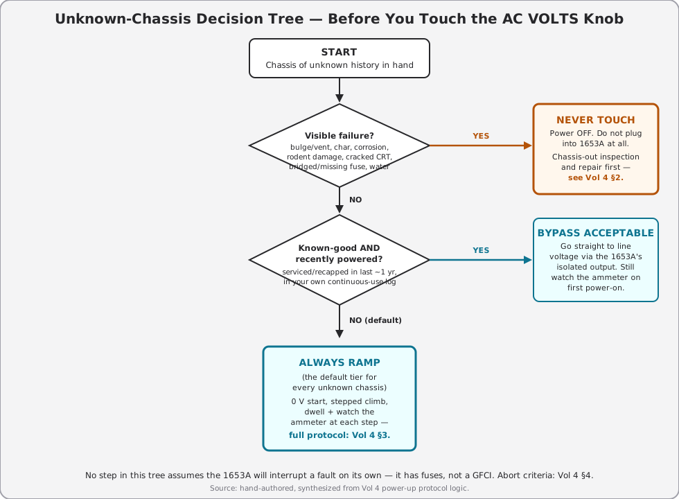
This is the reusable artifact of this volume — the one thing worth memorizing before any vintage chassis of unknown provenance gets near the ISOLATED OUTPUT receptacle. It sorts every chassis into exactly one of three tiers.
1.7.1 The Same Tree, in Table Form
Table 4 — The Same Tree, in Table Form
| Condition observed | Tier | Action | Detail in |
|---|---|---|---|
| Bulging/vented electrolytic, leaking wax-paper cap, char, cracked CRT envelope, rodent-chewed wiring, bridged or missing fuse, water damage, unknown burning smell before power is applied | NEVER TOUCH | Power off. Do not connect to the 1653A. Chassis-out inspection and repair first. | Vol 4 §2 |
| No visible failure, but history unknown, storage > ~1 yr, or this is truly the first power-up | ALWAYS RAMP (default tier) | 0 V start, stepped climb with dwell, watch the ammeter at every step | Vol 4 §3 |
| No visible failure, AND known-good (you serviced/recapped it yourself, or it’s been in your own recent continuous-use rotation) | BYPASS ACCEPTABLE | Go straight to line voltage via the isolated output; still watch the ammeter on first power-on | Vol 4 §1, Vol 5 §1 |
| Any current excursion, smoke, arcing sound, or burning/ozone smell appears during a ramp already in progress, regardless of starting tier | ABORT | Kill power immediately, do not restart until cause is found | Vol 4 §4 |
Note — “Bypass acceptable” is a statement about the chassis’s known state, not about the 1653A. The instrument still has no automatic fault interruption — no GFCI, only fuses — so bypassing the slow ramp is a judgment call about how much you already trust the DUT, not a judgment call about the tool.
1.8 A Note on Earth Bonding While the DUT Is Isolated
One instinct worth heading off here, ahead of Vol 3’s full treatment: because the 1653A’s output is isolated, it is tempting to think grounding no longer matters at all once a DUT is plugged into it. It matters differently, not less. The 1653A’s own chassis, case, and third-pin ground terminal are still bonded to building earth through its own power cord — only the DUT’s AC input is isolated from that reference. A scope or DMM ground clip landing on the DUT’s chassis is now safe from tripping a breaker or blowing a fuse (that’s what isolation bought), but the DUT’s chassis can still carry lethal AC potential relative to you, standing on an earth-referenced floor, if you become a second path to ground. The “one hand in your pocket” habit and an insulated floor mat are not optional extras for isolated work — they are the entire remaining safety margin. Full physiology and rule set: Vol 3 §4.
1.9 Depth Index — Where to Go From Here
Table 5 — Depth Index — Where to Go From Here
| Question | Answer lives in |
|---|---|
| How does the autotransformer winding/brush actually work, down to magnetizing and leakage current? | Vol 2 §1–§2 |
| What’s inside the GFCI-shaped hole in this instrument, and what protects it instead? | Vol 2 §3 (circuit-level), Vol 3 §3 (why it matters) |
| How accurate is the analog meter, and against what standard? | Vol 2 §5, Vol 5 §5 (calibration against a bench DMM) |
| Hot/neutral/ground theory, floating-chassis physiology, the one-hand rule, kV probe ratings | Vol 3 (canonical safety reference for the whole hub) |
| PCB oil, asbestos, selenium rectifiers, mercury switches, BeO dust — hazmat by era | Vol 3 §5 (hazmat catalog) |
| The actual 30-minute slow-ramp protocol, step by step | Vol 4 §3 |
| Cap-reform theory during a field power-up (vs. the standalone lab procedure) | Vol 4 §3 (field), Vol 5 §2 (standalone lab) |
| Current-watch triage — what each runaway pattern means | Vol 4 §4 |
| Day-to-day front-panel walkthrough, brown-out testing, current-limiter tricks | Vol 5 §1, §2, §4 |
| Common 1653A failure modes (brush wear, meter drift) and mods | Vol 5 §6, §7 |
| One-page bench cheatsheet, laminate-ready | Vol 6 |
1.10 1653A Spec Summary
Verified against B&K Precision’s published 1653A/1655A datasheet (2013) and instruction manual.
Table 6 — 1653A Spec Summary
| Parameter | 1653A value |
|---|---|
| Voltage adjustment range | 0–150 Vac, with 120 Vac input |
| Output current, continuous | 2 A (0–130 V), derates above 130 V per the manual’s Table 1 derating curve (exact intermediate values not extractable from PDF text — see Vol 2) |
| Output isolation (leakage) | < 0.1 mA (25 °C, 50% RH) |
| Voltage/current sensing | Sine-wave average, calibrated to read RMS |
| Metering | Single 2” dual-function analog meter, overrange protected; pushbutton VOLTS (0–150 V) / AMPS (0–2 A) scale select — reads one function at a time |
| Meter accuracy | ± 5% of full scale (25 °C) |
| Input power | 120 Vac ± 10%, 60 Hz, 300 VA |
| Protection | F1 line input fuse (3 A) + F2 internal output fuse (3 A) — replace to reset, no resettable breaker on the 1653A |
| Output receptacle(s) | 1, ISOLATED OUTPUT |
| Dimensions (H×W×D) | 5.5 × 6.5 × 10.5 in (140 × 165 × 267 mm) |
| Weight | 12 lb (5.5 kg) |
| Included accessories | Instruction manual, power cord |
Sources
- B&K Precision 1653A & 1655A AC Power Supplies datasheet (2013, v020713), fetched from rftesolutions.com — voltage/current range, isolation leakage spec (< 0.1 mA @ 25 °C/50% RH), meter accuracy (± 5% FS), dimensions, weight, input power (300 VA).
- B&K Precision Instruction Manual for Models 1653A & 1655A, Isolated, Variable AC Power Supply — Controls and Indicators (front/rear panel, confirms single 2” meter with pushbutton function switch, single ISOLATED OUTPUT receptacle, no GFCI/breaker/leakage-test controls on the 1653A); Specifications tables (confirms 1653A vs. 1655A deltas); Circuit Description p.29 (confirms T1 autotransformer → T2 isolation transformer signal path, F1 line fuse, F2 internal output fuse, no circuit breaker on 1653A); Table 1 maximum-output-current derating curve above 130 V.
- Wikipedia, Autotransformer — Variac trademark history (General Radio 1934–2002, ISE Inc. registration 2004, genericized-trademark status), cross-checked against multiple secondary sources (sound-au.com, variac.com, antiqueradios.com forum) that agree on the same timeline.
- UL 943 Class A GFCI trip-threshold figure (4–6 mA; inverse-time trip curve, faster at higher fault current) — general reference used only for the comparison callout distinguishing GFCI behavior from the 1653A’s actual fuse-only protection; not a claim that the 1653A contains a GFCI of any class.
- Staco Energy Products 3PN1010B specifications (multiple distributor listings — Radwell, DigiKey, Newark, RS Online) — used for the bare-autotransformer comparison row (0–140 V out, 10 A, fused output, no isolation stated).