B&K 1653A Variac · Volume 2
B&K 1653A Variac — Vol 2: Hardware & Circuit Theory
Schematic-grade theory of operation — the brush autotransformer, the series isolation transformer, the metering bridge, and the fusing scheme, traced stage by stage from the wall plug to the isolated output receptacle.
2.1 Scope of This Volume
Vol 1 established what the 1653A is and when to reach for it. This volume opens the case (on paper) and traces every stage of the signal path: the brush autotransformer, the series isolation transformer, the fusing, and the metering bridge. After this volume, the reader should be able to explain why a fault at 140 V output blows a different fuse than a fault at 20 V output, why the panel meter can misread a non-sinusoidal load, and exactly what does and does not sit between the wall plug and the DUT.
Two volumes build directly on this one: Vol 3 develops the isolation theory introduced in §“The Series Isolation Transformer” into the hub’s canonical mains-safety reference, and Vol 5 covers calibrating this unit’s meters against a bench DMM — a procedure that only makes sense once §“Metering Circuit” below is understood.
Note — a correction to the hub’s shorthand. The top-level project notes for this subproject originally described the 1653A as having “built-in isolation transformer + GFCI + fused output + metering.” Primary-source verification for this volume (B&K’s own datasheet and instruction manual) confirms the isolation transformer, the fused output, and the metering — but the 1653A has no GFCI of any kind: no differential-current sense element, no TEST/RESET button, no trip threshold. §“Overcurrent and Leakage Protection” below covers what the unit’s protection actually is (a 3 A line fuse plus a 3 A internal output fuse) and why “GFCI” was almost certainly imprecise shorthand for “extra safety feature beyond a bare autotransformer.” The hub-level project notes have been corrected to match.
2.2 Signal Path Overview
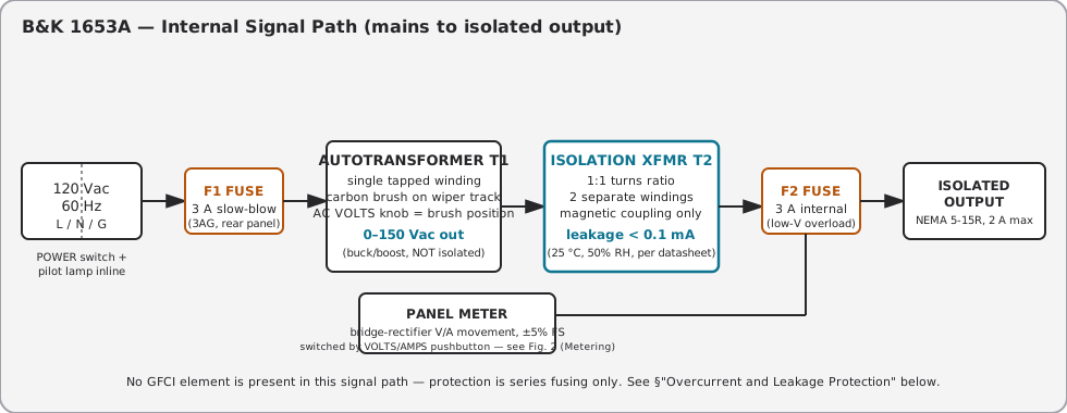
The 1653A is four stages in series between the wall plug and the ISOLATED OUTPUT receptacle: line fuse, variable autotransformer, isolation transformer, output fuse. A tap off the output feeds the panel meter. Nothing in this chain is a differential-trip device — every protective element is a fuse.
2.2.1 Full Specification Sheet
Pulled from B&K’s current 1653A/1655A datasheet and the shared instruction manual (both hosted at bkprecision.com); the 1655A column is included for contrast since several 1655A-only features (leakage test, circuit breaker, soldering-iron control) are relevant later in this volume.
Table 1 — Full Specification Sheet
| Parameter | 1653A (this unit) | 1655A (for contrast) |
|---|---|---|
| Voltage adjustment range | 0–150 Vac, input at 120 Vac | 0–150 Vac, input at 120 Vac |
| Output isolation leakage | < 0.1 mA (25 °C, 50% RH) | < 0.1 mA (25 °C, 50% RH) |
| Current range | 0–2 A | 0–3 A |
| Maximum current, isolated | 2 A continuous (0–130 V) | 3 A continuous, 4 A intermittent (0–130 V), intermittent ≤ 4 min followed by ≥ 5 min at ≤ 1 A |
| Peak inrush current | not specified (N/A on datasheet) | 30 A max, limited to one cycle |
| Voltage/current sensing | Sine-wave average, calibrated in RMS | Sine-wave average, calibrated in RMS |
| Meter scales | 0–150 V, 0–2 A | 0–150 V, 0–2 A / 0–4 A, 0–240/480 VA, 0–5000 µA leakage |
| Metering hardware | 2 in. meter, overrange-protected | 3¼ in. multicolor meter, overrange-protected |
| Typical meter accuracy | ±5% of full scale (calibrated @ 120 Vac) | ±5% FS volts/current, ±5% at 500 µA leakage |
| Overcurrent protection | F1 3 A slow-blow line fuse + F2 3 A internal fuse | CB1 3.15 A circuit breaker + 4 A rear-panel fuse |
| AC input | 120 Vac, 60 Hz, 300 VA | 120 Vac, 60 Hz, 600 VA |
| Operating temperature | 0 °C to +40 °C | 0 °C to +40 °C |
| Storage temperature | −30 °C to +60 °C | −30 °C to +60 °C |
| Dimensions (W×H×D) | 5.5 × 6.5 × 10.5 in (140 × 165 × 267 mm) | 10.5 × 5.7 × 12 in (267 × 145 × 305 mm) |
| Weight | 12 lb (5.5 kg) | 22 lb (10 kg) |
| Isolated output receptacles | one | two |
| GFCI | none documented | none documented |
Note — the datasheet’s “Meter Scale” row for the 1653A lists “0-140 VAC / 0-2 VAC” verbatim; the second line is almost certainly a datasheet typo for the 0–2 A current scale (the manual’s Controls & Indicators section and front-panel line drawing both show a single dual-purpose meter reading either 0–150 V or 0–2 A, selected by the same pushbutton).
2.3 The Variable Autotransformer
2.3.1 Single-Winding Principle
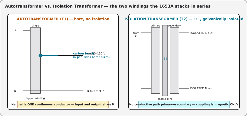
An autotransformer is a transformer with exactly one winding. Where a conventional (isolation) transformer has two electrically separate windings coupled only by a shared magnetic core, an autotransformer’s “primary” and “secondary” are the same winding — the input is applied across the full winding (or a fixed portion of it), and the output is taken from a tap partway along it. Every turn between the tap and one end of the winding is shared by both the input and the output circuits.
Because input and output share turns, an autotransformer cannot isolate. The neutral conductor that enters the unit is the same physical conductor (same winding end) that leaves it. This is the load-bearing fact for the rest of this volume: T1 alone buys nothing but a variable voltage. Isolation is a separate transformer (T2) stacked in series after it — see §“The Series Isolation Transformer” below.
Autotransformers show up throughout the power grid for exactly this reason: utility-scale autotransformers step transmission voltage down toward distribution levels at a fraction of the copper, core steel, and cost of an equivalent two-winding transformer, precisely because the shared-winding design needs to handle only the DIFFERENCE current between the two voltage levels rather than the full transformed power twice over. The tradeoff utilities happily accept — no isolation between the two voltage levels — is the exact same tradeoff a bare bench Variac accepts, and it’s why the 1653A can’t just be “a Variac” for hot-chassis work; it has to be a Variac PLUS a genuinely separate isolation stage.
2.3.2 Core Construction Note
General Radio’s original Variac design (and most descendants, including the Staco/Powerstat competitors covered in §“Comparison”) wind the autotransformer on a toroidal (donut-shaped) core, which keeps the exposed-turn wiper track as a clean circular path for the brush to ride and keeps the magnetic circuit short and efficient. B&K’s manual doesn’t specify T1’s core geometry explicitly in the sections reviewed for this volume, but the documented brush-and-wiper-track service procedure is only consistent with a toroidal (or similarly circular/cylindrical) winding form — a bar-wound or E-core autotransformer wouldn’t have a continuous circular track for a rotary brush to traverse. Flagged as inferred-from-service-procedure rather than directly confirmed by a construction diagram.
2.3.3 The Brush and Wiper Track
Fixed-tap autotransformers exist (a handful of discrete voltage points selected by a rotary switch), but the 1653A — like every General-Radio-derived “Variac”-class product — uses a continuously variable design: the winding is wound in a single layer around a toroidal (or, in some competing designs, a drum-shaped) core, and the insulating enamel is stripped from the top edge of each turn to expose bare copper. A spring-loaded carbon brush rides on that exposed track, contacting exactly one turn (or bridging two adjacent turns during the transition) at any given rotor position. Turning the front-panel AC VOLTS knob rotates the brush around the track, and because each turn represents a fixed increment of the total winding voltage, brush position maps linearly to output voltage.
The brush is a wear part. It carries the full output current at every voltage the knob touches, and every turn of the knob drags carbon across bare copper. §“Common Failure Modes” in Vol 5 covers brush wear, wiper-track oxidation, and dead spots in more detail; the geometry itself is enough context for this volume: the electrical connection from tap to output is a sliding mechanical contact, not a fixed solder joint, which is why a Variac-class autotransformer is serviceable (the brush is a replaceable part — B&K’s own maintenance section calls out “AUTO-TRANSFORMER BRUSH REPLACEMENT” as a documented procedure) in a way a conventional two-winding transformer is not.
2.3.4 Buck and Boost — Why Output Can Exceed Input
The winding isn’t tapped only between 0 V and “line voltage.” On most Variac-class autotransformers, extra turns are added past the line-voltage tap point, so the brush can travel past the position that reproduces the input voltage exactly (buck/boost neutral) and continue into a region where MORE turns are in the output circuit than are in the input circuit. Below that point the unit bucks (output < input); above it, the unit boosts (output > input).
This is why a “120 V in” autotransformer commonly outputs up to 132–140 V, and why the 1653A specifically is rated 0–150 Vac from a 120 Vac input — a 125% boost ratio, slightly more headroom than the 117% (140 V from 120 V) figure common on bare Staco/Powerstat units. The practical uses are brown-out simulation (buck below 120 V to margin-test a supply — see Vol 5) and overdriving a piece of equipment briefly past its rated input to observe headroom or find a breakdown threshold (the 1653A manual’s own CAUTION language: “the output voltage of the ac power supply is adjustable from 0 to 150 VAC. This is very useful in certain testing situations for stressing equipment beyond its normal operating range to determine its breakdown point”).
⚠ Danger — most 120 V-rated line equipment has a maximum input rating around 130 Vac. B&K’s own manual marks the 130–150 V portion of the 1655A’s meter scale in red for exactly this reason (the 1653A’s smaller meter has no colored zones, but the same physical limit applies). Above 130 V, treat every additional volt as a controlled overstress test, not a normal operating point — see Vol 4’s ramp protocol for how to approach this safely on unknown chassis.
Worked through the ratio: at the 150 V tap with 120 Vac applied to the winding’s line-voltage portion, the brush is riding on a point that represents 150/120 = 1.25× the number of turns used to reproduce line voltage exactly. Every turn past the line-voltage tap is boost — turns that exist in the output circuit but were never part of the input circuit’s ampere-turn balance at that setting. This is also why current rating tends to fall as voltage rises past the line-voltage point on a fixed-VA autotransformer: the same VA envelope spread over more output volts means proportionally less available current, which is exactly the shape of the derating curve in §“Output Current Derating Above 130 V” below.
2.3.5 Ventilation and Thermal Considerations
B&K’s manual precautions section is specific on this point: “the holes in the case provide convection cooling (hot air rises and escapes through the top vents, while cool air is drawn in to replace it through the bottom). Never block these ventilation holes with a manual, schematic diagram, other equipment, etc.” Both T1 and T2 are iron-core wound components dissipating real watts at continuous load — at 12 lb in a 5.5 × 6.5 × 10.5 in case, there isn’t much thermal mass to spare, and the convection path is the ONLY cooling mechanism (no fan). A 1653A buried under a service manual and a stack of test leads on a cluttered bench is a slow overheat waiting to happen, not a dramatic one — watch for a case that’s warmer than expected at the top vents during a long ramp session (Vol 4) as an early sign of restricted airflow, well before anything trips a fuse.
2.3.6 The 1653A’s Autotransformer in Context
Table 2 — The 1653A's Autotransformer in Context
| Property | Bare autotransformer (T1 alone) | What T1 contributes inside the 1653A |
|---|---|---|
| Winding count | 1 (single, tapped) | 1 (same) |
| Galvanic isolation | None — neutral is continuous input-to-output | None — isolation is added downstream by T2 |
| Voltage adjustment | 0 to ~117–125% of line, continuous | 0–150 V from 120 V in (continuous, brush-driven) |
| Current limit mechanism | Winding gauge / core saturation only | Winding gauge; current-limiting handed off to F1/F2 (see §5) |
| Serviceability | Brush replacement, wiper-track cleaning | Same — B&K documents a brush-replacement procedure |
| Metering | None (bare unit) | None on T1 itself — metering taps the isolated output (post-T2), see §“Metering Circuit” |
2.4 The Series Isolation Transformer
2.4.1 Galvanic Isolation: What T2 Actually Breaks
T2 is a conventional two-winding transformer wired in series after T1’s variable output. Its job is narrow and specific: it removes the electrically continuous path between the building’s neutral/ground reference and the DUT. Primary and secondary are magnetically coupled (flux through a shared core) but have no conductive connection — no shared winding, no shared terminal. Whatever the DUT’s chassis does relative to the isolated secondary, it cannot push current back through T1 to the building neutral, because there is no wire for that current to travel on.
Isolation is a NECESSARY condition for hot-chassis-safe servicing, not a SUFFICIENT one — T2 removes the earth-return path, but the DUT’s chassis can still be at a lethal potential relative to the isolated secondary’s other terminal, and relative to any OTHER grounded object a technician might simultaneously be touching (a grounded soldering iron, a bench lamp, another piece of grounded test gear). Vol 3 exists specifically because “isolated” is so often misheard as “safe to touch,” and the distinction matters enough that it’s the hub’s single canonical safety volume rather than a paragraph repeated in every instrument’s writeup.
This is the property that makes the 1653A safe to use on “hot chassis” gear — AC/DC sets, transformerless TVs, anything where the metal chassis is directly connected to one side of the AC line. Vol 3 develops this into the hub’s full mains-safety reference (the floating-chassis hazard, the one-hand rule, why a grounded scope probe is fine downstream of T2 but is a direct short upstream of it); this volume stops at the transformer-theory boundary.
2.4.2 1:1 Turns Ratio and Why
T2’s turns ratio is 1:1 — it passes 0–150 Vac through unchanged in magnitude, contributing isolation and nothing else to the voltage math. (Contrast this with a step-down isolation transformer, which would ALSO isolate but would change the voltage; the 1653A deliberately keeps voltage-setting and isolation as two independent, separately-adjustable functions — T1 sets the voltage, T2 isolates it, and neither stage does the other stage’s job.)
2.4.3 Magnetizing Current vs Leakage Current
Two distinct small currents matter on an isolation transformer, and it’s easy to conflate them:
- Magnetizing current is the (mostly reactive) current T2’s primary winding draws with no load connected, simply to establish the core’s operating flux. It’s normal, it’s a property of every transformer, and it flows entirely within the primary-side circuit — it never crosses to the secondary and has nothing to do with shock hazard.
- Leakage current is the (mostly capacitive, some resistive) current that DOES bridge primary to secondary — through interwinding capacitance and through the finite insulation resistance between windings. This is the number that matters for shock hazard and for GFCI coexistence, because it’s the current that can find its way from the isolated secondary back to earth through some other path (a person’s body, a grounded test lead, stray capacitance to the case).
B&K publishes this figure directly for the 1653A: output isolation leakage less than 0.1 mA, measured at 25 °C / 50% relative humidity. That’s roughly 50× under the 4–6 mA UL 943 Class-A GFCI trip band (see Vol 3’s GFCI-vs-isolation discussion for what that trip band means and why it’s relevant even though this unit doesn’t implement it) — low enough that the transformer’s own construction leakage is a non-issue next to whatever leakage the DUT itself contributes once it’s plugged in.
Note — 0.1 mA is a manufacturing spec for the transformer’s own leakage, measured with nothing connected to the isolated output. It is not a claim about total system leakage once a decades-old, possibly-degraded DUT is plugged in — that number is dominated by the DUT, not by T2. This is why the 1655A’s LEAKAGE TEST function (§“Metering Circuit” below) exists as a diagnostic measurement to be taken with the DUT connected, not a spec you can just read off the 1653A’s datasheet.
2.4.4 Leakage Current and GFCI Coexistence
Why does an isolation transformer’s leakage number matter for GFCI coexistence, given that this unit doesn’t have one? Two independent reasons carry forward to later volumes:
- If the 1653A is plugged into a GFCI-protected wall outlet or a GFCI-protected shop circuit (increasingly common on modern branch circuits, particularly in damp-location or garage/basement bench setups), the transformer’s own leakage current — plus whatever magnetizing current and stray capacitance the whole chain contributes — adds to the primary-side leakage budget that upstream GFCI is watching. At <0.1 mA, T2 itself won’t meaningfully move that needle. This is a reassurance, not a warning.
- A floating secondary can defeat a DOWNSTREAM GFCI — if you tried to add GFCI protection on the isolated-output side (after T2), a genuine fault on the DUT (chassis shorted to one output leg) would NOT show up as a line/neutral current imbalance the way it would on a grounded circuit, because the isolated secondary has no return path to compare against. This is precisely why, in products that DO combine isolation with GFCI, the GFCI element sits on the MAINS side of the isolation transformer, sensing the primary current — never on the isolated secondary. Vol 3 §“GFCI vs Isolation” develops this into the hub’s canonical explanation of why the two techniques solve different problems and why order-of-stages matters.
2.5 Overcurrent and Leakage Protection
2.5.1 What the 1653A Actually Has: Dual-Fuse Protection
Per B&K’s own Circuit Description section (instruction manual, “MAINTENANCE AND CALIBRATION” / “CIRCUIT DESCRIPTION” pages), the 1653A’s protection is two fuses in series, nothing else:
- F1 — a 3 A slow-blow fuse (type 3AG), on the rear panel, in series with the mains input ahead of T1. It protects against excessive INPUT current — the failure mode of a heavily loaded output at the higher end of the voltage range, where a given output current draws a correspondingly large input current through T1.
- F2 — a 3 A fuse INTERNAL to the chassis (not user-accessible from the rear panel on the 1653A), positioned to protect the autotransformer winding itself against excessive OUTPUT current at LOW output voltages — the case where a heavy or shorted load pulls large current through only a few turns of T1 without pulling a correspondingly large input current, so F1 alone wouldn’t see it in time.
Both are simple thermal/melting-element fuses. Neither senses a current imbalance between line and neutral; neither has a TEST button or a RESET latch; neither has a millisecond-class trip-time rating. They protect the transformer and wiring from overcurrent, not the operator from leakage-to-ground.
2.5.2 Why Two Fuses: Fault-Current Paths at High vs Low Output Voltage
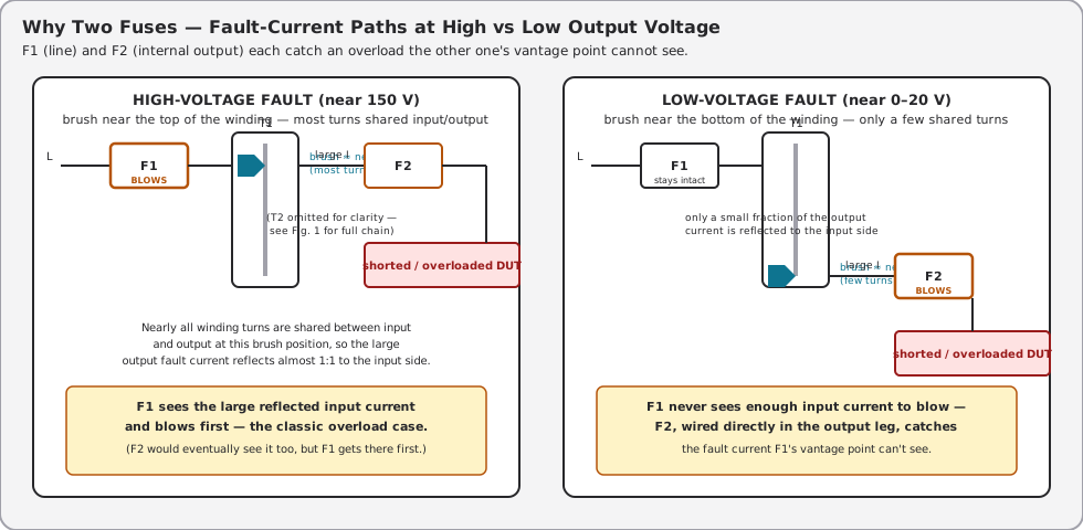
F1 and F2 aren’t redundant — each catches an overload the other one physically cannot see, and the reason comes straight out of the autotransformer turns-ratio math in §“Buck and Boost” above:
- A fault near the top of the range (output voltage close to 150 V) puts the brush near the far end of the winding, with most of T1’s turns in the output circuit. A shorted or heavily overloaded DUT here draws a large output current, and because nearly all the winding is shared between input and output at this brush position, that output current is reflected almost 1:1 onto the input side — F1 sees a correspondingly large input current and blows.
- A fault near the bottom of the range (output voltage close to 0 V) puts the brush near the near end of the winding, with only a handful of turns in the output circuit. A short here can still pull a large OUTPUT current (bounded mainly by winding resistance and wiring, not by the tiny number of turns in circuit) — but the ampere-turns balance across those few shared turns means only a small fraction of that current is reflected back to the input side. F1 may never see enough input current to blow, even while the winding and brush are absorbing a damaging fault current. F2, wired directly in the output leg after T2, sees the full fault current regardless of brush position and blows on it.
This is exactly the case the manual’s own derating language (§“Output Current Derating Above 130 V”) and brush-damage warning point at: “higher current may damage the variable auto-transformer where the brush contacts the winding” — F2 exists specifically to catch the low-voltage, high-output-current fault that F1’s line-side vantage point can miss.
2.5.3 Fuse Failure-Mode Triage
The manual’s own “RETURNING FOR SERVICE” checklist boils down to a two-question decision tree before anyone opens the case or ships the unit out:
                    1653A produces no output
                              │
                 ┌────────────┴────────────┐
                 │                         │
          Pilot light OFF?          Pilot light ON,
                 │                  meter reads 0 V/A
                 ▼                  regardless of knob?
        Check line cord / plug            │
        / POWER switch first               ▼
                 │                  F1 is almost certainly
        Cord/switch OK?             good (it would have
                 │                  killed the pilot too)
                 ▼                          │
        F1 (rear-panel line fuse)           ▼
        has blown — severe overload   F2 (internal fuse) has
        at the HIGHER end of the      blown — severe overload
        voltage range                 at the LOWER end of the
                 │                    voltage range, where output
                 ▼                    current was high relative
        Replace ONLY with 3 A         to input current
        slow-blow 3AG. Do NOT                │
        upsize the fuse value.               ▼
                                      Requires opening the case —
                                      not a field-replaceable part
                                      from outside the enclosure
Useful in its own right for service work, and structurally the same kind of “which failure produced which symptom” table Vol 4/6 use elsewhere in the hub:
Table 3 — Useful in its own right for service work, and structurally the same kind of "which failure produced which symptom" table Vol 4/6 use elsewhere in the hub
| Symptom | Likely cause | What to check |
|---|---|---|
| Unit stops entirely, pilot light OFF, no output at any knob position | F1 (rear-panel line fuse) blown — severe overload at HIGHER output voltage | Pull F1, inspect for open element; replace ONLY with 3 A slow-blow 3AG — do not upsize |
| No output, pilot light stays ON | F2 (internal fuse) blown — severe overload at LOWER output voltage, where output current was high relative to input current | Requires opening the case; internal fuse, not user-serviceable from outside — treat as a bench repair, not a field swap |
| Meter reads voltage/current normally but output receptacle is dead | Bad receptacle contact, wiring fault downstream of F2, or brush not making contact at that rotor position | Check brush contact (§“The Brush and Wiper Track”); verify continuity receptacle-to-F2 |
| Pilot light doesn’t illuminate at all, unit completely dead | Line cord, POWER switch, or a fault ahead of F1 (F1 blowing doesn’t kill the pilot on this design — see row 1) | Check cord/plug/switch before assuming F1 |
⚠ Danger — B&K’s manual carries this caution jointly for both models in the family (“never bypass the circuit breaker or fuses, or replace a fuse with a higher-value one”) — on the 1653A specifically there is no circuit breaker to bypass, only F1 and F2, so read it as: never bypass F1 or F2, and never replace either with a higher-value fuse. A larger fuse “may create a fire and safety hazard, or cause serious damage to the equipment.” The fuse values (3 A / 3 A on this model) were chosen against the autotransformer’s actual thermal limits, not arbitrarily.
2.5.4 Reconciling the Hub’s “GFCI” Shorthand
The hub’s top-level project notes originally described the 1653A as having “isolation transformer + GFCI + fused output + metering.” Both B&K’s datasheet and the instruction manual’s Circuit Description independently confirm the protection is fuses only — no GFCI. The most likely explanation is simply an imprecise compression: “isolation + fused + metered, safe to use on hot-chassis gear” became “isolation + GFCI + fused + metered” somewhere along the way, conflating the general category of “extra safety feature beyond a bare autotransformer” with the specific mechanism of a GFCI. That shorthand has been corrected hub-wide; this volume documents the actual mechanism (§“What the 1653A Actually Has: Dual-Fuse Protection” above) in its place.
2.6 Metering Circuit
2.6.1 Rectifier-Type AC Meter Movement
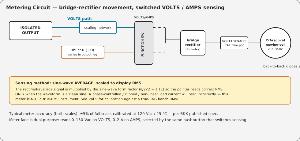
The 1653A’s panel meter is a D’Arsonval (moving-coil, permanent-magnet) DC movement — inherently a DC instrument — made to read AC by rectifying the AC signal first. Per the manual’s circuit description: “the meter is connected across a bridge rectifier to provide the dc necessary for meter operation.” This is the classic rectifier-type AC meter: a full-wave bridge converts the AC input to pulsating DC, the moving-coil movement responds to the average of that pulsating DC, and the scale is printed (or the sensing resistor is trimmed) so the pointer reads the equivalent RMS value assuming a pure sine wave (the datasheet’s own phrasing: “sine wave average, calibrated in RMS”). Back-to-back diodes are wired directly across the meter movement as overrange/overvoltage protection, clamping excessive swings and incidentally giving the meter its stated overrange protection.
This is a different technology from a moving-iron movement (which uses the AC current itself to magnetize a piece of soft iron against a fixed field, and can read true AC without any rectification, but is generally coarser and less sensitive) — worth naming explicitly since moving-iron is the OTHER common technology for panel-meter AC sensing and it’s easy to assume that’s what a rugged bench Variac uses. It is not, on this unit; B&K’s own circuit description settles it.
2.6.2 Voltage Sensing Path
With the function switch in VOLTS, the meter is connected (through a scaling network and the VOLTAGE CAL trim pot) directly across the ISOLATED OUTPUT, reading 0–150 V.
2.6.3 Current Sensing Path
With the function switch in AMPS, a 1 Ω series-sensing resistor in the output leg develops a voltage proportional to output current; that voltage is applied to the same bridge-rectifier/meter path through the AMPS CAL trim pot, reading 0–2 A. (The 1655A’s higher-current 4 A scale uses two series 0.5 Ω resistors and senses across only one of them for the expanded-range reading — included here only for contrast; the 1653A uses the single 1 Ω / 0–2 A arrangement.)
2.6.4 Meter Accuracy and ANSI C39.1
B&K publishes the 1653A’s meter accuracy as ±5% of full scale, calibrated at 120 Vac / 25 °C, for both the volts and amps scales. ANSI C39.1 (“Requirements for Electrical Analog Indicating Instruments”) is the standard that defines accuracy CLASSES for exactly this kind of panel meter — commonly-cited classes run from the tightest (0.25%, 0.5% — laboratory-grade) through mid-grade (1.0%, 1.5%, 2.0%) to utility/general-purpose grades (2.5%, 3.0%, and a 5.0% class at the loose end). A ±5% FS meter sits at the loosest common ANSI C39.1 accuracy grade — appropriate for a “watch the trend, catch a gross fault” bench instrument, not for anything that needs to be trusted as a voltage or current REFERENCE.
Table 4 — Meter Accuracy and ANSI C39.1
| Accuracy class (typical ANSI C39.1 grades) | Where it’s used | Where the 1653A’s meter sits |
|---|---|---|
| 0.25% / 0.5% | Laboratory reference & standards-grade instruments | — not this class |
| 1.0% / 1.5% | Precision switchboard / panel instruments | — not this class |
| 2.0% / 2.5% | General industrial panel meters | — not this class |
| 3.0% | Utility-grade panel meters | close, but 1653A is looser still |
| 5.0% | Loosest common panel-meter grade — trend/monitoring use | 1653A meter (±5% of full scale, per B&K datasheet) |
Note — the exact ANSI C39.1 class-boundary percentages above are the commonly-cited set from panel-meter vendor literature, not independently confirmed against the ANSI C39.1 text itself (a paid standard) for this volume. The load-bearing fact — that ±5% FS is B&K’s own published number, and that it’s the loose end of the panel-meter accuracy spectrum — is solid regardless of the exact class boundaries above it.
Put in absolute terms rather than percentages: ±5% of a 150 V full-scale VOLTS reading is ±7.5 V anywhere on that scale — meaning a meter reading “120 V” could genuinely be anywhere from 112.5 V to 127.5 V at the instrument’s rated accuracy, before any waveform-shape error from §“Reading Error Sources” is even factored in. On the AMPS scale, ±5% of the 2 A full-scale figure is ±0.1 A — a meaningful fraction of the total range when watching for the kind of slow current creep that signals a reforming (or failing) electrolytic during a Vol 4 power-up ramp. Read the meter as a trend indicator and a gross-fault catcher, not as a calibration-grade reference; that’s what “5% class” panel meters are FOR, and it’s why Vol 5’s calibration-verification procedure exists at all — to establish, for THIS specific unit, where within that ±5% band its actual error sits.
2.6.5 Reading Error Sources — Non-Sinusoidal Loads
Because the movement is average-responding and the scale is calibrated for a sine wave, ANY load current or voltage that isn’t a clean sine will read with an error whose direction and magnitude depend on the waveform’s crest factor and form factor. Two cases worth flagging explicitly for a tube-restoration bench:
- A DUT with a phase-controlled dimmer, an SCR-based supply, or a switch-mode auxiliary circuit downstream of the isolated output will present a chopped or distorted current waveform to the AMPS sensing path. The meter will NOT read true RMS current in this case — it will read whatever the average-times-1.11 approximation produces for that particular waveform, which can be significantly off from the DUT’s actual RMS draw.
- A capacitor-input rectifier (the overwhelmingly common tube-gear power-supply topology) draws current in narrow, high-crest-factor pulses near the peak of each half-cycle rather than a smooth sinusoid — even though the voltage the 1653A supplies stays sinusoidal, the current it’s asked to read on the AMPS scale is exactly this kind of distorted, pulse-shaped waveform. Expect the AMPS reading during ramp-up (Vol 4) to be a rough indicator, not a precise number, once B+ current stabilizes on real tube gear.
Vol 5’s calibration procedure addresses this directly by checking the 1653A’s meter against a true-RMS bench DMM (Fluke 87V or 8846A class) — see Vol 5 §“Calibration / Verification” for the comparison method and where the analog movement’s accuracy class is expected to land relative to the DMM.
2.7 Terminal Block, Receptacles, and Wiring
2.7.1 ISOLATED OUTPUT Receptacle
The 1653A has a single ISOLATED OUTPUT receptacle on the front panel (the 1655A has two, for greater convenience running two DUTs — though B&K’s manual specifically warns that only ONE “hot chassis” piece of equipment should ever be connected at a time, even on the dual-outlet 1655A, “unless the line-to-chassis relationship is identical” between the two DUTs — a shock hazard otherwise exists between the two chassis). It’s a standard-format duplex-style AC outlet face (NEMA 5-15R geometry, per the manual’s front-panel line drawing); nothing about the receptacle ITSELF signals “this circuit is isolated” to someone glancing at the bench — it looks like any other wall outlet, which is exactly why isolated-output benches should be clearly labeled.
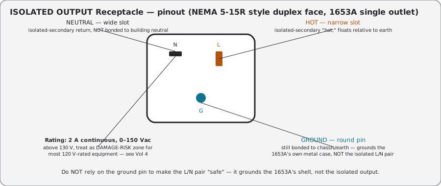
⚠ Danger — the ground pin on the ISOLATED OUTPUT receptacle grounds the 1653A’s OWN metal case (a real safety feature — it keeps the instrument’s chassis at earth potential). It does not ground either isolated conductor. A DUT plugged into this outlet still floats relative to earth on its hot/neutral pair exactly as isolation theory predicts — see Vol 3 for the full implications, especially for a DUT whose OWN case is normally tied to one side of the AC line.
2.7.2 Rear-Panel Layout
Rear panel carries the AC power cord (line-cord entry, not detachable IEC on this model per the manual’s figures) and the F1 fuse holder. No additional switches, receptacles, or protective devices live on the rear panel of the 1653A (contrast the 1655A, which adds a rear-panel soldering-iron outlet, a circuit breaker, and a leakage-probe jack — none of which the 1653A has).
2.7.3 Terminal / Receptacle Reference Table
Table 5 — Terminal / Receptacle Reference Table
| Point | Function | Notes |
|---|---|---|
| Line cord | AC mains in, 120 Vac / 60 Hz | Not detachable (integral cord) per manual figures |
| F1 fuse (rear panel) | Line-side overcurrent protection | 3 A slow-blow, 3AG; user-replaceable |
| F2 fuse (internal) | Output-side overcurrent protection at low voltage | 3 A; NOT user-accessible without opening the case |
| ISOLATED OUTPUT (front) | DUT power, isolated 0–150 Vac, 2 A max | NEMA 5-15R-style face; single outlet on 1653A |
| Chassis ground | Bonds 1653A’s own case/panel to earth | Present at the receptacle’s round pin AND at the line cord’s ground conductor |
| AC VOLTS knob | Sets T1 brush position → output voltage | 0–150 V, continuous |
| VOLTS/AMPS pushbutton | Selects meter function and scale | Alternate-action; push to latch AMPS (in), push again to release to VOLTS (out) |
2.8 Output Current Derating Above 130 V
B&K’s manual includes a dedicated derating chart (“Table 1. Maximum Output Current Derating”) plotting maximum permissible output current against output voltage from 130 V to 150 V for both models. The accompanying text is unambiguous about WHY the chart exists and how to use it: “it is very important to observe the maximum current derating (Table 1) above 130 volts… even at low voltages, the maximum output current should never exceed 4 amps for Model 1655A or 2 amps for Model 1653A. Higher current may damage the variable auto-transformer where the brush contacts the winding.”
For the 1653A specifically, the manual states plainly that continuous-duty output current should not exceed 2 A “for continuous duty or intermittent duty operation” and that the meter’s full-scale 2 A indication IS the ceiling — there is no intermittent-duty allowance above 2 A on this model the way the 1655A gets a 4-minutes-at-4-A / 5-minutes-at-1-A intermittent allowance. Above 130 V, the derating curve trends the maximum continuous current DOWN from the 2 A full-scale figure toward the 150 V end of the range — consistent with the turns-ratio math in §“Buck and Boost” (more output volts from the same VA envelope means proportionally less available current) — but this volume does not reproduce exact intermediate amperage values off the chart, since a plotted curve read secondhand from a rendered PDF page risks a transcription error on a number that directly bears on not cooking the autotransformer’s brush contact. Read Table 1 directly from the manual before running the 1653A hard anywhere above 130 V output.
⚠ Danger — never exceed the maximum output current rating of the unit. Excessive output current can damage the variable autotransformer. Keep output current as low as possible, and never exceed the maximum rating even briefly at low voltages — B&K’s own language (jointly worded for both models): never bypass the circuit breaker or fuses. On the 1653A that means F1 and F2 specifically — never bypass either fuse, and never replace one with a higher-value fuse to “push through” a derating limit.
2.9 Symptom-to-Stage Quick Reference
With four series stages (F1 → T1 → T2 → F2) plus a metering tap, it helps to have one table mapping an observed symptom back to the stage most likely responsible, cutting across the individual sub-sections above:
Table 6 — With four series stages (F1 → T1 → T2 → F2) plus a metering tap, it helps to have one table mapping an observed symptom back to the stage most likely responsible, cutting across the individual sub-sections above
| Observed symptom | Most likely stage | Why |
|---|---|---|
| No output, pilot OFF | F1 (line fuse) or upstream (cord/switch) | F1 sits ahead of everything; losing it kills the pilot along with the output |
| No output, pilot ON | F2 (internal output fuse) | F2 sits after T1/T2; the pilot circuit taps power ahead of F2, so it stays lit |
| Output present but voltage won’t reach full 150 V, or dead spots as the knob turns | T1 brush/wiper contact | Worn brush or oxidized wiper track — mechanical contact issue, not electrical failure (Vol 5) |
| Output voltage correct, but DUT chassis still reads continuity to earth ground | Not a 1653A fault at all — check DUT wiring | T2 provides isolation on the OUTPUT pair; a DUT with its own internal ground strap or a miswired test setup can reintroduce a ground path downstream of the isolation transformer |
| Meter reads voltage/current, but the number drifts or seems implausible under a non-sinusoidal load | Metering circuit, not a fault | Expected behavior of an average-responding meter under a distorted waveform — see §“Reading Error Sources” |
| Meter needle pinned or reading erratically | Meter movement or its overrange-protection diodes | Bridge-rectifier/moving-coil movement fault, or the DUT is drawing well past the scale’s range |
| Case warmer than expected during a long ramp | Ventilation restriction, not necessarily a fault | Check nothing is blocking the top/bottom vents before assuming a winding problem |
2.10 Comparison: 1653A vs Bare Autotransformers
2.10.1 What a Bare Autotransformer Gets You
The Staco 3PN1010B and the Superior Electric Powerstat 116B are both current-production (or recently so), enclosed, plug-in variable autotransformers — the direct “no-name eBay Variac” category the 1653A is competing against on the bench, minus the isolation/metering value-add. Both are meaningfully HIGHER current than the 1653A (10 A class vs the 1653A’s 2 A), because their target market is general-purpose lab/industrial voltage control, not specifically low-current tube-gear servicing where isolation matters more than headroom.
Table 7 — What a Bare Autotransformer Gets You
| Spec | B&K 1653A | Staco 3PN1010B | Powerstat 116B |
|---|---|---|---|
| Output range | 0–150 Vac (from 120 V in) | 0–140 Vac (from 120 V in) | 0–140 Vac (from 120 V in) |
| Current rating | 2 A continuous | 10 A constant-current | 10 A (up to ~13 A for constant-impedance loads, per vendor literature) |
| Power rating | 300 VA input | 1.4 kVA | comparable class |
| Isolation transformer | Yes — series 1:1 T2 | No | No |
| Metering | Built-in V/A panel meter | None (some variants add a simple voltmeter, not standard) | None standard |
| Overcurrent protection | Dual fuse (F1 line, F2 output) | Fused NEMA output receptacle, illuminated switch | Similar enclosed/fused configuration |
| Weight | 12 lb (5.5 kg) | 11 lb | comparable class |
| Typical use case | Isolated, metered, low-current bench work — tube-gear power-up | General lab/industrial voltage control, higher current, no isolation need | Same category as Staco |
2.10.2 What You’re Paying For
The bare autotransformer wins on raw current capacity and cost-per-amp for general voltage-control work — 10 A vs the 1653A’s 2 A is a real difference for anything beyond signal-level tube gear. But neither Staco nor Powerstat unit isolates: connect either one’s output directly to a hot-chassis DUT and the chassis is exactly as electrically live as it would be plugged straight into the wall, because the neutral conductor runs continuously from the building’s neutral, through the autotransformer’s winding, to the DUT — precisely the situation §“Galvanic Isolation” above describes. The 1653A’s entire reason to exist on THIS bench, at less than a quarter of the bare units’ current rating, is that it adds the isolation transformer and the metering that turn a voltage-control tool into a hot-chassis-safe, current-watched power-up tool. For anything that doesn’t need isolation — driving a known-safe, grounded-chassis load at higher current — a bare Staco or Powerstat is the more capable, cheaper choice; see Vol 1’s decision tree for when each applies.
It’s also worth being explicit about what neither category buys: none of these three units — 1653A, Staco 3PN1010B, or Powerstat 116B — implements a differential-trip GFCI. The 1653A’s edge over the bare units is isolation and metering, full stop; it is not a “safer” device in the ground-fault-interruption sense, because none of the three implements that function at all. A shop technician who wants BOTH isolation AND GFCI-class earth-fault protection on one instrument (see Vol 3’s GFCI-vs-isolation discussion for why the two solve different problems) is looking for a different (and less common) product category than any of the three covered in this comparison — worth knowing before assuming the 1653A’s isolation transformer is “doing GFCI’s job too.”
2.11 Internal Construction
The autotransformer (T1) and isolation transformer (T2) are both wound components occupying most of the 1653A’s internal volume, per the weight (12 lb in a 5.5 × 6.5 × 10.5 in case — dense for the enclosure size, consistent with two iron-core wound components rather than one). The manual’s brush-replacement procedure implies the autotransformer’s winding and brush assembly are accessible without a full teardown (consistent with routine service being expected over the unit’s life), while F2’s internal, non-rear-panel-accessible mounting implies at least partial disassembly is needed to reach it.
2.12 Service-Part Equivalents
B&K does not publish exact manufacturer part numbers for the internal transformers, the brush assembly, or the meter movement in the materials reviewed for this volume — treat the entries below as class/spec descriptions to match against, not exact SKUs, until Jeff cross-references against the actual unit’s markings or a parts list from B&K support.
Table 8 — Service-Part Equivalents
| Component | 1653A spec / class | Sourcing note |
|---|---|---|
| F1 (line fuse) | 3 A slow-blow, type 3AG (¼” × 1¼” glass or ceramic body) | Widely stocked; B&K’s own manual explicitly warns against substituting a higher-value fuse |
| F2 (internal fuse) | 3 A, exact type/form factor not published | Confirm physical fuse holder type from teardown before ordering — likely also 3AG given F1’s spec, but unverified |
| T1 (autotransformer) | Single-winding, brush-type, 0–150 V from 120 V in, rated for ≥2 A continuous secondary current | Not independently serviceable as a drop-in part; brush IS a documented replaceable wear item |
| T2 (isolation transformer) | 1:1, rated for ≥2 A continuous, leakage < 0.1 mA class | Generic replacement would need to match this leakage class, not just the VA rating, to preserve the safety margin — do not substitute an arbitrary 1:1 isolation transformer without checking its leakage spec |
| Meter movement | 2 in. D’Arsonval, dual-scale (0–150 V / 0–2 A), ±5% FS | Panel-meter class part; exact OEM source not identified in this volume |
| Line cord | Integral (non-detachable), standard 3-wire grounded | Standard replacement part, not model-specific |
⚠ Danger — never substitute the isolation transformer with a generic 1:1 unit sourced by VA rating alone. The published leakage spec (<0.1 mA) is a construction-quality claim about interwinding capacitance and insulation, not something a random surplus isolation transformer of the same power rating is guaranteed to meet — and leakage current, not VA rating, is what determines whether the “isolated” output is actually safe to touch relative to earth. See Vol 3.
Practically, for a unit this age-class (current-production but electromechanically simple — the same basic brush-autotransformer-plus-isolation-transformer architecture General Radio shipped decades ago), the F1 line fuse is the only part likely to need routine replacement, and it’s a generic, universally-stocked 3AG-body 3 A slow-blow — any electronics-supply house or hardware-store fuse assortment covers it. The wound components (T1, T2) and the meter movement are the parts that would actually stop the bench if they failed, and none of the three has a documented drop-in replacement part number in the materials reviewed for this volume. If Jeff’s unit ever needs a transformer or meter repair, the realistic paths are: (1) a local transformer-rewind shop working from the measured turns ratio and wire gauge off the failed unit, (2) a parts unit off the used-test-equipment market (B&K 1653A units turn up used regularly given how long this model ran), or (3) contacting B&K support directly for a parts-availability check before assuming a part is unobtainable.
2.13 Cross-Reference Index
Table 9 — Cross-Reference Index
| This volume’s topic | Where it’s developed further |
|---|---|
| Isolation theory, hot-chassis hazard, GFCI-vs-isolation, one-hand rule | Vol 3 (canonical hub safety reference) |
| Slow-ramp power-up procedure, current-watch triage, abort criteria | Vol 4 (canonical hub power-up workflow) |
| Meter calibration/verification against a bench DMM, brush/wiper service, common failure modes | Vol 5 |
| The unknown-chassis decision tree, when to reach for the 1653A vs a bare autotransformer | Vol 1 |
| Bench cheatsheet distillation of ramp profile, current-watch tree, voltage spot-checks | Vol 6 |
Sources
- B&K Precision 1653A/1655A Data Sheet (bkprecision.com, hosted PDF, “v053018”) — output voltage range, current rating, output isolation leakage (<0.1 mA @ 25 °C/50% RH), voltage/current sensing method (“sine wave average, calibrated in RMS”), meter accuracy (±5% FS), AC input, dimensions, weight. Directly fetched and read for this volume.
- B&K Precision 1653A/1655A Instruction Manual (bkpmedia.s3.amazonaws.com, hosted PDF) — TEST INSTRUMENT SAFETY section, FEATURES, full SPECIFICATIONS tables for both models, CONTROLS AND INDICATORS (front/rear panel figures and callouts, including fuse and receptacle descriptions), OPERATING INSTRUCTIONS/PRECAUTIONS (max output voltage/current cautions, Table 1 current-derating curve), CIRCUIT DESCRIPTION (variable voltage circuit, metering circuit, soldering-iron control circuit — the primary source establishing NO GFCI is documented and the meter is a bridge-rectifier-fed moving-coil movement), MAINTENANCE AND CALIBRATION (fuse replacement procedure, brush maintenance mention). Directly fetched, read in full across pages 1–30, and used as the primary technical source for this volume — this is the source that surfaced the GFCI discrepancy flagged throughout.
- Staco Energy Products 3PN1010B — output range (0–140 Vac), current rating (10 A constant-current, 1.4 kVA), physical spec (11 lb, ventilated steel case, fused NEMA output, illuminated switch) — from Staco/distributor product pages (radwell.com, galco.com, digikey.com, and Staco’s own variac.com cut-sheet/handbook PDFs).
- Superior Electric Powerstat 116B — output range (0–140 Vac), current rating (10 A, up to ~13 A for constant-impedance loads per vendor copy) — from Specialty Product Technologies (current Powerstat manufacturer) and distributor listings.
- UL 943 Class A GFCI trip specification — 4–6 mA trip band (nominal 5 mA ±1 mA), inverse-time trip curve (t = (20/I)^1.43 s — seconds near the 5–6 mA threshold, <25 ms only at large fault currents in the hundreds-of-mA range) — cross-checked against multiple secondary sources (UL Solutions “Special Purpose Ground-Fault Circuit Interrupters,” electrical-engineering-portal.com, Mike Holt electrical forums) describing UL 943 Class A requirements; not read from the UL 943 standard text itself (paywalled), flagged for a reviewer with standard access.
- ANSI C39.1 accuracy classes — general panel-meter accuracy class structure (0.25% through 5.0% FS grades) — pieced together from panel-meter vendor/distributor literature (Eaton, Crompton Instruments, Continental Control Systems AN-136) rather than the ANSI C39.1 standard text itself (also paywalled); the specific class-boundary percentages in the table under §“Meter Accuracy and ANSI C39.1” are flagged as the least-certain numeric claim in this volume.
- Variac trademark history — General Radio trademark 1934–2002, genericized usage, re-registered by Instrument Service Equipment in 2004 — cross-checked against Wikipedia’s “Genrad” and “Autotransformer” articles and sound-au.com’s “The Variac” article; consistent across sources.
- Rectifier-type vs moving-iron AC meter movement theory — general electrical-engineering reference material (allaboutcircuits.com “AC Voltmeters and Ammeters,” electrical-engineering-portal.com, testbook.com) used only for the generic operating-principle description; the SPECIFIC claim that the 1653A uses a bridge-rectifier-fed moving-coil movement (not moving-iron) comes from the B&K instruction manual’s own Circuit Description, not from this general material.