B&K 1653A Variac · Volume 3
B&K 1653A Variac — Vol 3: Bench Safety & Mains Isolation Theory
The canonical hazard reference for the TestEquipment hub — hot/neutral/ground, floating chassis, isolation vs GFCI, and a year-dated hazardous-materials catalog for vintage gear
This volume is the hub’s canonical safety reference. Every later vintage-tube deep dive in
TestEquipment — Heathkit IP-32,
Heathkit SP-2717A,
Heathkit TT-1, and everything that comes after —
links back here instead of re-deriving mains-isolation theory, shock physiology, or the
hazardous-materials catalog. General bench-discipline rules that apply hub-wide (not specific to
mains isolation) live in _shared/legal_ethics.md; read both before
unfamiliar HV or tube-era work. Vol 1 covers the unknown-chassis decision tree at the survey level;
Vol 4 turns the theory below into the step-by-step power-up procedure.
3.1 “Ground” Is Not One Thing — Terminology Used Throughout This Volume
Half of the confusion in mains-safety discussions traces back to the word “ground” doing three different jobs. This volume uses these terms precisely, and it’s worth fixing them before the rest of the volume leans on them:
Table 1 — leans on them
| Term | What it actually is | Carries current in normal operation? | Referenced to earth? |
|---|---|---|---|
| Earth ground | The literal dirt/rod/water-pipe connection at the service entrance — the physical planet | No | Is the reference |
| Equipment grounding conductor (the green wire / bare wire / 3rd prong) | A dedicated safety conductor bonding a chassis back to the panel’s ground bus, which is bonded to earth | No (only during a fault) | Yes, via the panel bond |
| Neutral (the white/gray wire) | The normal AC return conductor | Yes — this is the working return path | Yes, but only at the single panel bond point (§2) |
| Chassis ground / chassis common | Whatever a given piece of gear’s designer decided to call “0 V” on its own internal reference — a sheet-metal chassis, a ground-plane trace, a B− bus | Sometimes (it’s often also the return path inside the instrument) | Not necessarily — this is the crux of §3 |
| Signal ground / scope ground | The reference a given measurement is taken against — the scope probe’s ground clip, a DMM’s COM lead | Only fault current, ideally | Yes, on any 3-prong-grounded instrument — its case is bonded to the equipment grounding conductor |
| Floating | Not referenced to earth ground at all — could be anywhere within its own local circuit’s swing | N/A | No, by definition |
The dangerous confusion is treating “chassis ground” and “earth ground” as synonyms. On a properly designed, transformer-isolated, 3-prong-grounded piece of gear, they are the same node — that’s the whole point of the safety-ground conductor. On a floating-chassis radio or TV (§3), “chassis ground” is a complete misnomer: the chassis is not grounded to earth at all, it’s referenced to one leg of the AC line, and calling it “ground” out of habit is exactly the trap that gets an AC/DC set’s chassis touched with the same casual confidence you’d extend to a grounded instrument’s case.
3.2 The Hot / Neutral / Ground Triangle
A US residential branch circuit is a 120 Vac single-phase tap off a center-tapped 240 V utility secondary. Three conductors reach the outlet, and the relationship between them — not any one wire in isolation — is what makes the circuit safe or dangerous to touch.
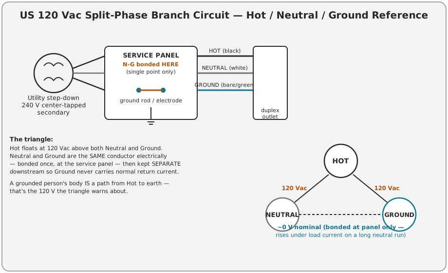
- Hot (black) — the energized conductor. 120 Vac RMS relative to neutral, and (nominally) 120 Vac relative to ground, because neutral and ground are the same potential at the source.
- Neutral (white/gray) — the grounded current-carrying conductor. It carries the normal return current of the circuit. It is bonded to ground at exactly one point: the service panel (or the transformer, on some utility topologies). Downstream of that bond, neutral and ground are kept physically separate.
- Ground (bare/green) — the safety conductor. It carries no current in normal operation. Its only job is to give fault current a low-impedance path back to the panel so an overcurrent device (breaker or fuse) opens fast, and to hold any bonded metal chassis at (nominally) 0 V so a person touching it isn’t the alternate path to earth.
Note — Because neutral carries load current and has nonzero conductor impedance, neutral-to-ground voltage is not exactly 0 V in the field — it rises with load current and with distance from the panel (a few tenths of a volt is normal on a heavily loaded branch; more than ~2 V hot-to-ground vs hot-to-neutral asymmetry on an idle circuit is worth investigating — bootleg ground, loose neutral, or a wiring error). This volume treats it as ~0 V for hazard analysis; the deviation is a wiring-integrity signal, not a safety margin to rely on.
Why this triangle matters for bench work: every hazard analysis in this volume reduces to one question — what two points is current allowed to flow between, and does that path include a human body or an earth reference it shouldn’t? A DUT chassis that is supposed to sit at ground potential (0 V) but doesn’t is the single most common vintage-gear hazard, covered next.
3.3 Floating-Chassis Sources — Why They’re Lethal
“Floating chassis” means the chassis metal is not referenced to earth ground through a dedicated safety-ground conductor or an isolation transformer — it’s referenced to some point in the AC line itself, deliberately (cost-reduction designs) or accidentally (a fault). Three vintage topologies account for nearly all floating-chassis gear a hobbyist encounters:
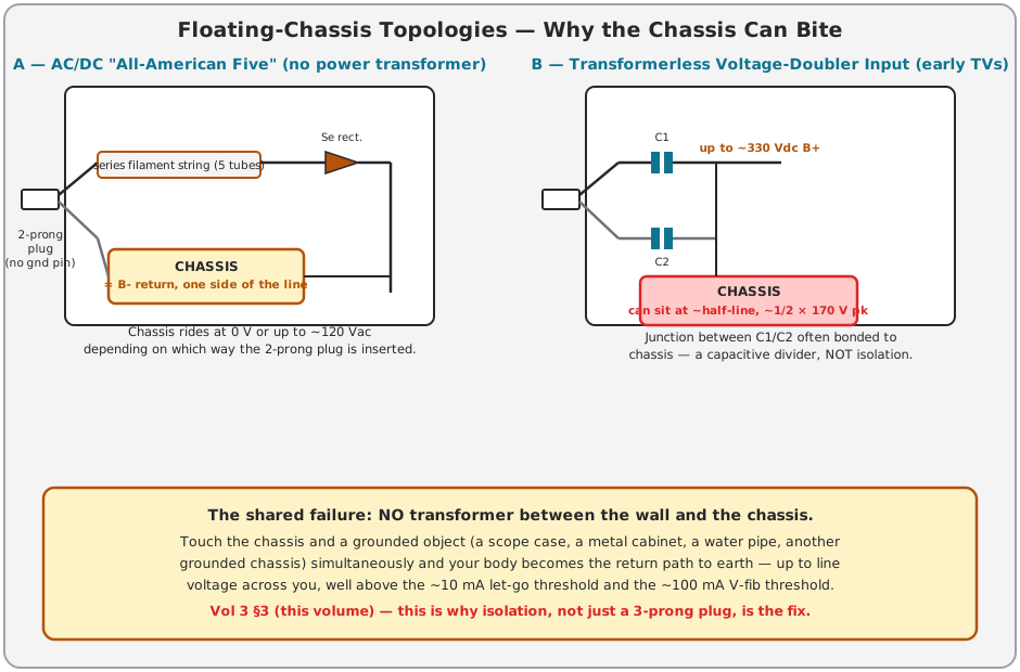
3.3.1 AC/DC “All-American Five” radios
The classic five-tube AC/DC superheterodyne (1938 into the 1960s) has no power transformer at all. The tube filaments are wired in series (their voltage ratings sum to roughly line voltage — a common lineup is 12BE6/12BA6/12AT6/50C5/35W4, summing to ~121 V) and that series string ties directly across the line. A selenium or vacuum rectifier off the same line supplies B+. The chassis is B− return — one side of the incoming AC line, full stop. Because the plug is a non-polarized 2-prong plug (or a polarized plug wired without regard for which blade is which), the chassis can land at:
- ~0 V relative to earth if the plug happens to put the chassis side on neutral, or
- Up to ~120 Vac relative to earth if the plug is flipped, putting the chassis side on hot.
There is no way to tell which state you’re in by looking at the set. A hobbyist measures it (meter, hot-to-chassis, both plug orientations) before ever touching the chassis with the set powered.
3.3.2 Transformerless “hot-chassis” TVs
Many tube-era and early solid-state TVs (roughly 1950s–1970s, the classic “hot chassis” design, still found in some later color sets) use the same transformerless philosophy at higher power: the line feeds a full-wave or half-wave rectifier directly, sometimes through a voltage-doubler input stage (see below), and the chassis is bonded to one leg of that rectifier network. B+ on these sets can be 150–170 Vdc (half-line rectified) up to 300+ Vdc (doubled), and the chassis carries it as a return path the same way the AC/DC radio’s chassis does — just at higher voltage and current capability. This is the origin of the “hot chassis” warning silk-screened on the back of period TV cabinets and cited (with caveats) by service literature of the era.
3.3.3 Voltage-doubler input stages
A voltage doubler (two rectifier diodes/tubes and two capacitors, no transformer) turns a 120 Vac line into roughly 300–340 Vdc B+ — enough to run a TV’s horizontal-output stage without a bulky, expensive power transformer. The midpoint between the two doubler capacitors is frequently tied to chassis. That point sits at a capacitively divided fraction of the line swing, commonly cited informally as “half line” — this is not a precise design constant, it depends on the doubler topology and loading, so treat any transformerless-doubler chassis as “somewhere between 0 V and full rectified B+” rather than trusting a specific fraction.
⚠ Danger — None of these three topologies provide galvanic isolation. Touching the chassis of any of them while also touching a grounded object — a metal-cased scope, a water pipe, another grounded chassis, a concrete floor through worn shoe soles — puts your body across up to full line voltage. This is the textbook fatal-shock scenario in home-shop electronics, and it is why hot-chassis equipment is the load-bearing reason the 1653A carries a built-in isolation transformer rather than being a bare autotransformer.
Vol 1’s unknown-chassis decision tree starts by asking exactly this question — is the chassis referenced to line, or isolated — before deciding how (or whether) to bring the unit up.
3.4 What Isolation Actually Buys You
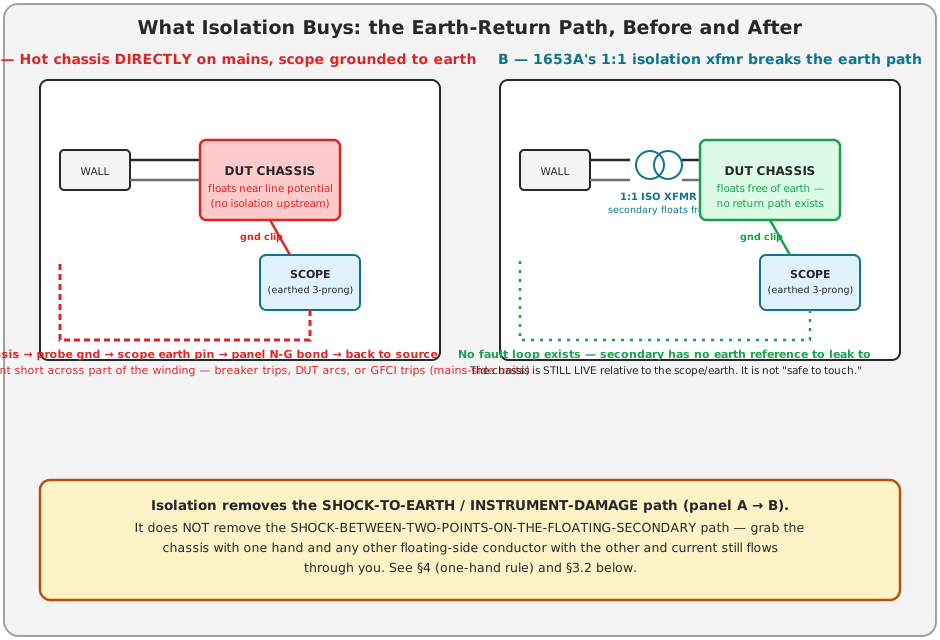
The 1653A’s isolation transformer is a separate winding set from the autotransformer brush assembly — see Vol 2 §2 for the internal architecture. Electrically it is a conventional 1:1 (or near-1:1) transformer: two windings coupled by a shared core, no direct wire connection between primary and secondary. That single fact — no galvanic path — is the entire mechanism behind every benefit isolation provides.
3.4.1 The ground-loop break
Without isolation, clipping a grounded oscilloscope probe to a hot chassis closes a circuit: chassis → probe ground lead → scope chassis → scope’s earth pin → building ground → the neutral-ground bond back at the service panel → back to the source. If the chassis is at line potential, that’s a near dead short across part of the transformer/rectifier network — enough current flows to trip the branch breaker instantly, blow a fuse, or (worse) not trip anything and instead cook a trace, arc a connector, or push several amps through the probe ground lead and its clip.
With the DUT powered through the 1653A’s isolation transformer, the DUT’s “line” is now the floating secondary. There is no bond between that secondary and earth anywhere in the circuit. Clip the scope ground to the DUT chassis and there is nothing for fault current to return through — the loop described above simply doesn’t exist, because one of its two ends (the DUT side) isn’t connected to earth at all. That’s the entire value proposition: isolation converts “grounding my test gear to this DUT is a hazard/an instant fault” into “grounding my test gear to this DUT does nothing electrically interesting.”
3.4.2 What isolation does NOT do
⚠ Danger — Isolation does not make the DUT chassis “safe to touch.” The secondary is still fully energized — it’s just no longer referenced to earth. Touch two different points on the floating secondary side simultaneously (the chassis and a hot lead, or two points across the winding) and current flows through you exactly as it would on a non-isolated circuit — your body closes the loop instead of earth. Isolation removes ONE hazard (chassis-to-earth shock, and the associated instrument-damage/fault-trip problem) and leaves the other (across-the-floating-secondary shock) fully intact.
This is why isolation and the one-hand rule (§7) are not alternatives — they solve different halves of the same problem. Isolation removes the “walked into a ground loop by accident” hazard; the one-hand rule mitigates the “touched two live points on purpose while probing” hazard that isolation cannot touch.
3.5 GFCI vs Isolation — Two Different Bench-Safety Concepts
⚠ Correction (2026-07-17), verified against the B&K 1653A/1655A instruction manual: the 1653A itself has no GFCI of any kind — no GFCI, no GFCI TEST/RESET button, no earth-leakage trip. Its only protective features are the 1:1 isolation transformer (removes the earth reference, covered in §4 above) and fuses (a 3 A line/input fuse plus an internal 3 A output fuse — see Vol 2 §2 and Vol 4). GFCI is nonetheless a real, useful concept for a vintage-gear bench, and it’s worth understanding what it does and doesn’t buy you relative to isolation — which is what this section covers, as general bench-safety theory, not as a description of anything inside this instrument. If you want ground-fault protection on this bench, the way to get it is a separate, external GFCI outlet or in-line GFCI adapter, upstream of the 1653A’s line cord — see the placement discussion below.
Isolation and GFCI protect against different fault mechanisms, and they are not interchangeable — neither is “better,” they solve different halves of the earth-referenced-fault problem, and one (isolation) can actively defeat the other (GFCI) if placed on the wrong side of it.
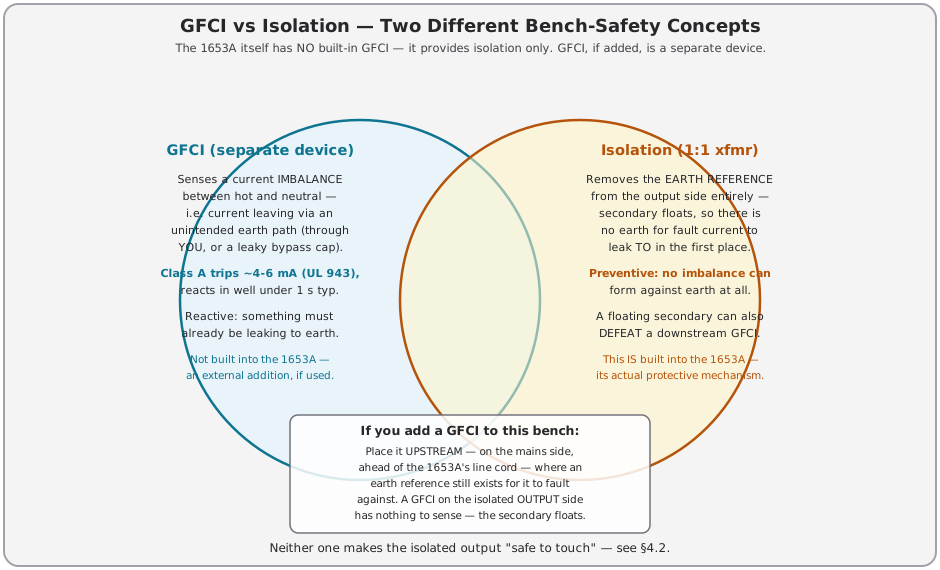
Table 2 — GFCI vs Isolation — Two Different Bench-Safety Concepts
| GFCI (a separate device, e.g. an external GFCI outlet, per UL 943) | Isolation transformer (1:1, built into the 1653A) | |
|---|---|---|
| Mechanism | Differential current sensor compares hot and neutral current; trips on imbalance | Breaks the galvanic (DC/low-frequency) path between primary and secondary |
| What it catches | Current already leaking to earth through an unintended path (a person, a leaky bypass cap, a wet chassis) | Nothing to “catch” — prevents the earth-referenced fault loop from existing at all |
| Typical trip point | Class A: trips in the 4–6 mA range per UL 943 (informal industry shorthand: “5 mA class”); response well under 1 s at the trip threshold, faster at higher fault current | N/A — not a sensing device |
| Protects | The operator and the branch circuit, at the point where a real earth-referenced fault current would otherwise keep flowing indefinitely | Both the DUT (from becoming a short across the source when its chassis is grounded) and the operator’s test equipment (from becoming part of a fault loop) |
| Does NOT protect against | A fault with no earth-return path (e.g., across an isolated floating secondary) — nothing to sense | Shock between two points on the isolated secondary itself; does not “sense” or “trip” on anything |
| On the 1653A specifically | Not present in this instrument — the 1653A provides isolation and fuses only (see correction note above) | This is the 1653A’s actual protective mechanism — between the autotransformer output and the isolated output receptacle; see Vol 2 §2 for the exact block order |
| If you add one anyway | Place it upstream, on the mains side, ahead of the 1653A’s line cord — see the note below | N/A — already built in |
| Failure interaction | A downstream floating secondary has no earth reference — it can mask/defeat a GFCI placed after it, because there’s nothing for the GFCI to sense an imbalance against | If the isolation transformer’s secondary is (incorrectly) bonded to earth downstream, it stops being isolation and re-creates the fault loop a GFCI is meant to catch |
Note — A floating secondary defeating a downstream GFCI is the reason that, on a bench with the 1653A plus a separately added GFCI, the GFCI belongs on the mains side — ahead of, not after, the isolation transformer. On the mains side, an earth reference still exists (the building’s neutral-ground bond) for the GFCI to fault against, so it can do its job protecting the operator at the wall-plug/line-cord end of the bench. Putting a GFCI on the isolated output side (downstream of the 1653A) would largely be theater — with the secondary floating, there’s rarely an earth-referenced imbalance for it to detect. The 1653A does not ship with either option built in — it provides isolation only; a GFCI upstream is an optional addition, not a factory feature of this unit.
3.6 Earth-Bonding Discipline When Working on an Isolated DUT
Isolation removes the automatic earth reference — it does not forbid a deliberate one. There are legitimate reasons to intentionally bond an isolated DUT’s chassis to earth while working on it, and knowing when to do so (and when not to) is bench discipline, not just theory:
- Do bond the DUT chassis to earth (a single clip lead to a known-good ground point) when you want your scope/DMM ground references to read true DC/AC levels against earth-referenced test gear, and you have first confirmed (with a meter, DUT unpowered) which chassis point is actually the intended return (B− or chassis common) rather than blindly clipping to sheet metal that might be a floating shield.
- Don’t bond if the whole point of the exercise is characterizing a hot-chassis design’s behavior relative to line (e.g., verifying the AC/DC radio’s chassis-to-neutral vs chassis-to-hot readings in both plug orientations per §3.1) — bonding it defeats the measurement.
- One bond point only. If you bond the DUT chassis to earth and also have the isolation transformer energizing it, you’ve made a deliberate, controlled version of the same loop §4.1 warns against for the unintentional case — that’s fine as a single, known, current-limited connection (a clip lead, not a fault), but don’t also introduce a second incidental earth reference (a grounded test-lead body, a bench mat, a second grounded instrument’s chassis touching the DUT) or you’ve built an unplanned second bond point and reintroduced the ground-loop hazard piecemeal.
- Re-isolate before touching. If you bonded the chassis to earth for a measurement, remove that bond before doing hands-on chassis work (component swaps, probing) — with the bond removed, the chassis reverts to floating and a scope/meter ground clip is once again electrically inert to it, which is the safer default state for hands-in-the-chassis work per §4.1.
Worked example — aligning a transformer-isolated tube radio’s IF stage against a grounded signal generator:
- DUT is a transformer-powered radio (real power transformer, chassis tied to its own B− bus) running off the 1653A’s isolated output. Confirm with a meter, DUT unpowered, that chassis-to-either-1653A- output-terminal reads an open circuit or a high, non-zero resistance — consistent with an isolated, non-earth-referenced chassis, per §1’s terminology table (this is a “chassis common,” not yet “earth ground”).
- Clip a single lead from the DUT chassis to a known-good earth point (the 1653A’s own chassis ground terminal, if the unit provides one, or the third-prong ground of another grounded instrument’s power cord — not a random metal object).
- Now the DUT chassis and the signal generator’s chassis (also earth-grounded) share a common reference — the signal generator’s ground lead and the scope’s ground clip both read true against the DUT’s B− bus, and IF-can alignment measurements are meaningful.
- When the alignment is done and it’s time to reach into the chassis for a physical adjustment (a slug tune, a component swap), remove the bond clip first, dropping the chassis back to isolated/ floating per the “re-isolate before touching” rule above.
This sequencing — bond only for the specific measurement that needs it, unbond before hands-on work — is the general pattern; adapt the specific ground point and instruments to whatever’s actually on the bench.
3.7 The One-Hand Rule and Shock Physiology
Isolation (built into the 1653A) and GFCI (a separate device, if added to the bench) both defend against earth-referenced faults. Neither defends against the shock path that matters most while actively probing a live circuit: hand-to-hand, straight across the chest.
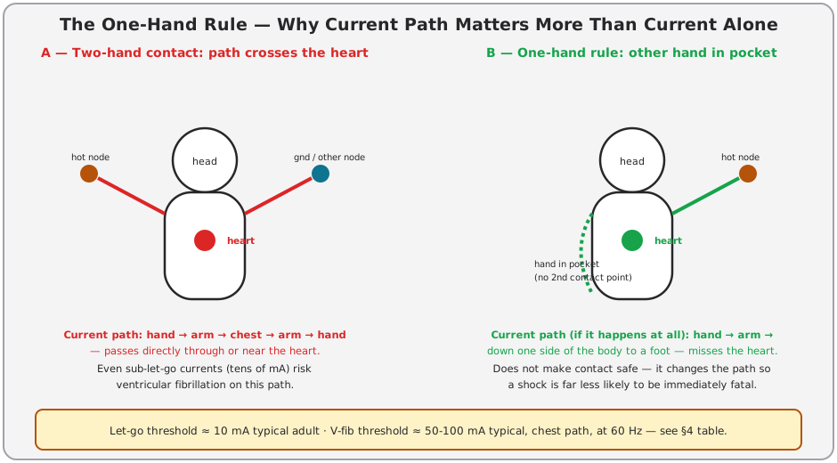
The rule: when probing anything above roughly 50 V (the ballpark commonly cited as the low end of “can be hazardous under adverse conditions” — dry skin has resistance in the many-kΩ range, but wet skin, broken skin, or a low-impedance grip drops that by an order of magnitude or more), keep one hand in a pocket or behind your back. Probe with the other hand only. Stand on a dry, non-conductive surface if practical. This is standing bench discipline per _shared/legal_ethics.md §“High voltage” and applies to every HV instrument in this hub.
Why it works — the physiology: current, not voltage, is what injures or kills, and path determines how much of that current crosses the heart. Two hands on two different potentials puts the chest — and the heart inside it — directly in the current path. One hand on a live point with the other hand electrically isolated (in a pocket, no second contact point) means any current that does flow has to find a path down one side of the body toward a foot, which is far less likely to cross the heart at a dangerous current density. The one-hand rule doesn’t lower the voltage you’re exposed to or guarantee you won’t be shocked — it changes the path so a shock is far less likely to be immediately fatal.
Table 3 — The One-Hand Rule and Shock Physiology
| Current (60 Hz AC, hand-to-hand path) | Typical physiological effect |
|---|---|
| ~1 mA | Threshold of perception |
| ~5–10 mA | ”Let-go” threshold region — roughly 5–7 mA typical for women, 7–10 mA typical for men; above this, involuntary muscle contraction can prevent releasing the conductor |
| ~10–20 mA | Sustained muscle contraction, pain, can impair breathing muscles with prolonged exposure |
| ~50–100 mA | Ventricular-fibrillation risk region for a chest-crossing path at mains frequency; commonly cited threshold ~100 mA, with risk beginning notably below that on some models |
| Several hundred mA – amps | Severe burns, cardiac arrest, respiratory paralysis; risk of fibrillation gives way to risk of outright cardiac/respiratory arrest at higher current |
⚠ Danger — These thresholds are population-average estimates from physiology literature, not guarantees — individual susceptibility varies with body mass, skin condition, contact area, exposure duration, and path. Treat every number in this table as “this is where things get dangerous,” not as a safe-below/unsafe-above line. The GFCI Class A trip point (4–6 mA, §5) is set specifically to be below the let-go threshold in this table — that’s the design intent, not a coincidence.
3.7.1 Why “50 V” and not some other number
Ohm’s law is the whole reason the 50 V figure shows up so often in bench-safety literature: it’s a current threshold (roughly the let-go/perception boundary in the table above) divided by an assumed body-resistance floor. Dry, unbroken skin commonly presents on the order of tens of kΩ to a few hundred kΩ hand-to-hand, which would put a 50 V exposure’s resulting current well under 1 mA — trivial. The 50 V guideline exists because that skin-resistance assumption is fragile: wet skin, sweat, a broken callus, or a tight/sustained grip on a conductor can drop effective body resistance by one to two orders of magnitude, at which point the same 50 V drives current into the perceptible-to-let-go range from the table above. Treat 50 V as “the point where a bad day at the bench (sweaty hands, a humid shop, a cut on a finger) turns a non-event into a real shock,” not as a hard physics boundary — which is also why the one-hand rule is framed as “anything above roughly 50 V,” not as a bright line at exactly 50 V.
3.8 Scope-Probe Voltage Ratings and kV Nodes
A grounded oscilloscope probe is itself a hazard source if its voltage rating is exceeded — the failure mode is not “the reading is wrong,” it’s “the probe’s insulation arcs over, punctures, or the probe compensation network fails short,” any of which can put line or HV potential onto the scope input, the probe barrel, or your hand.
Table 4 — Scope-Probe Voltage Ratings and kV Nodes
| Probe type | Typical voltage rating | Typical use | Failure mode if exceeded |
|---|---|---|---|
| 1× passive probe | Often only 150–300 V (many common 1× probes are NOT rated for mains, let alone HV — check the barrel markings) | Low-level signal tracing, audio, digital logic | Insulation breakdown, arc-over at the probe tip or BNC boot; can conduct fault current into the scope input and the operator’s hand |
| 10× passive probe (general purpose) | Commonly 300–600 V CAT II | General bench work, most tube-circuit low-voltage stages | Same as above; 10× probes are the most-used probe and the most-often mis-rated for HV nodes |
| 10× HV-rated probe | Typically rated 1.2–2 kV (some to 4–6 kV) — confirm the specific probe’s datasheet, ratings are not universal across “HV probe” as a category | B+ rails, plate supplies on tube gear, moderate HV nodes | Arc-over inside the probe body; can propagate to the scope chassis |
| Dedicated high-voltage probe (e.g., 40 kV class) | Purpose-built, often 100:1 or 1000:1, rated to tens of kV | CRT anode potential, transmitter PA plate voltage, any multi-kV node | These exist specifically because no general-purpose probe is safe at these nodes |
⚠ Danger — A 300 V-rated probe on a 2 kV node is not a measurement error — it’s a fire and shock hazard. The probe’s insulation is not a suggestion; it’s rated for a specific standoff voltage, and exceeding it can arc through the probe body, through your hand holding it, or through the BNC shield straight into the scope’s chassis ground — at which point the fault current has a path to earth (or to you) regardless of any isolation or GFCI upstream, because the fault originated inside your test lead, past all of that protection. Know the voltage of the node before you touch a probe to it — read the schematic/service manual, or measure conservatively with a DMM rated for the expected range first.
Cross-reference: the Heathkit IP-32 and SP-2717A HV power-supply deep dives (both sibling instruments in this hub) generate exactly the multi-kV nodes this table warns about — probe-rating discipline there is non-negotiable, not optional.
3.8.1 CAT overvoltage categories — what the rating on a meter or probe actually means
A test instrument’s voltage rating isn’t just a number — modern meters and probes are also rated by IEC 61010 overvoltage category (CAT), which describes where in the power system the instrument is safe to connect, because transient energy available at a fault rises sharply the closer you are to the utility service. This matters on a vintage-gear bench because it’s easy to reach for a CAT I DMM (rated for low-energy electronic circuits) and use it on a 1653A’s mains-referenced input side, or vice versa.
Table 5 — CAT overvoltage categories — what the rating on a meter or probe actually means
| Category | Where it applies | Typical bench example |
|---|---|---|
| CAT I | Protected low-energy electronic circuits, signal levels | Inside a battery-powered device, low-voltage signal/control circuitry |
| CAT II | Single-phase receptacle-connected loads, local branch-circuit wiring | Testing at a wall outlet, most bench power supplies, the 1653A’s output side once isolated |
| CAT III | Distribution-level wiring, permanently-installed loads, panel-adjacent circuits | Testing at a subpanel, a permanently wired appliance circuit |
| CAT IV | The utility service entrance itself — the origin of the installation | Testing at the meter base / service drop |
For nearly all work in this hub — probing inside a vintage radio, TV, or tube-testing instrument that’s plugged into a wall outlet — CAT II is the practical floor. A meter/probe combination rated only CAT I on a mains-connected DUT is under-rated for the transient energy available at that outlet, even though the steady-state voltage (120 Vac) is well within the meter’s numeric range. Voltage rating and CAT rating are two independent specs on a probe or meter — both must cover the node being measured.
3.9 X-Ray Emission from High-Voltage CRTs
A cathode-ray tube accelerates electrons toward the phosphor screen using the anode’s high voltage. When those electrons decelerate on impact (at the phosphor and at the shadow mask/aperture grille in color tubes), some of that kinetic energy converts to Bremsstrahlung X-rays. Emission is negligible well below roughly 10 kV anode potential and becomes an actual regulatory/shielding concern as anode voltage climbs into the mid-teens of kV and beyond — this is why U.S. federal regulation (21 CFR Part 1020, the FDA’s performance standard for ionizing-radiation-emitting electronic products) specifically governs television receivers and other CRT-equipped consumer products.
- Vintage color TVs typically run CRT anode (ultor) voltage in the 20–27 kV range at full brightness — comfortably in the X-ray-relevant band, which is exactly why the FDA standard exists for them and why the high-voltage/flyback section of a color TV chassis is a shielded, enclosure-interlocked area in original factory design.
- Bright-trace and high-writing-speed oscilloscopes such as the Tektronix 7904/7904A (500 MHz) use a ~24 kV scan-expansion (post-accelerator/PDA) CRT specifically to brighten a fast trace, and carry the same X-ray consideration as a result. Note the 1 GHz 7104, despite being the fastest 7000-series mainframe, is a different case: it gets its brightness from a microchannel-plate (MCP) CRT that multiplies beam electrons, so it only needs a moderate ~12.5 kV accelerating voltage — borderline on the X-ray threshold below, not a firm “high anode voltage” example.
- Ordinary vintage bench scopes (dual-trace 10–100 MHz analog scopes, the bulk of what shows up on a hobby bench) typically run CRT anode voltage well under this range and are not a meaningful X-ray concern in normal operation with the case intact.
⚠ Danger — The controlling factor is anode voltage and an intact enclosure/shielding, not instrument category. Never operate a CRT-equipped instrument with the case, bezel, or shielding removed if you don’t know its anode voltage — restore the shield before extended operation on anything you suspect runs in the mid-teens-of-kV-or-above range. This is in addition to, not instead of, the anode-discharge procedure in _shared/legal_ethics.md (short the anode to chassis through a 1 MΩ resistor before touching — the CRT stores that charge after power-down independent of whether it’s also an X-ray concern while running).
Rough anode-voltage bands by device class (bench triage only — always confirm against the specific unit’s schematic/service manual rather than assuming a class-typical value):
Table 6 — unit's schematic/service manual rather than assuming a class-typical value)
| Device class | Typical anode/ultor voltage | X-ray-relevant? |
|---|---|---|
| Small CRT indicator tubes (radar/scope indicator tubes, some VTVM “magic eye” tuning indicators) | Well under 10 kV | No |
| Ordinary dual-trace vintage bench oscilloscope (10–100 MHz analog) | Roughly 1.5–5 kV | No, at normal case-intact operation |
| Bright-trace / high-writing-speed scope mainframe (e.g., Tek 7904/7904A, 7934, with post-accelerator/scan-expansion PDA CRT) | ~20–24 kV | Yes — this is exactly the class the case/bezel warning targets |
| Tek 7104 (1 GHz mainframe, microchannel-plate CRT) | ~12.5 kV | Borderline — the MCP amplifies beam current for brightness at a moderate accelerating voltage, not a firm “Yes” case |
| Vintage black-and-white TV | Roughly 9–15 kV | Borderline — treat as relevant, case intact regardless |
| Vintage color TV | ~20–27 kV | Yes — factory-shielded and interlocked by original design for this reason |
This table exists for bench triage — “which of my instruments should I be extra careful not to run with the case off” — not as a substitute for checking the actual service manual, which will state the design anode voltage directly when the manual survives.
3.10 Hazardous-Materials Catalog
Vintage gear predates a great deal of current hazardous-materials regulation. The materials below are common enough in tube-era test equipment and consumer electronics that a hobbyist working on anything built before roughly 1980 should be able to recognize them on sight before disassembly proceeds.
Table 7 — Hazardous-Materials Catalog
| Material | Year range commonly found | Where found in test/vintage gear | How to identify | Handling |
|---|---|---|---|---|
| PCB (polychlorinated biphenyl) oil | Manufactured pre-1979 (TSCA manufacturing ban took effect 1979; equipment already in service was allowed to remain in use) | Large oil-filled power transformers, oil-filled HV capacitors, some ballasts | Nameplate/label reading “Pyranol,” “Inerteen,” “Askarel,” “Aroclor,” or similar trade names; oily residue with a faint sweetish/chlorinated odor on a leaking unit | Don’t disturb an intact unit. If leaking: ventilate the area, don’t touch the oil bare-handed, don’t dispose of it as ordinary e-waste — PCB disposal is EPA-regulated (40 CFR Part 761). When in doubt about an unlabeled pre-1979 oil-filled transformer/cap, treat it as PCB-suspect until tested |
| Asbestos | 1950s–1960s construction common; declined through the 1970s–80s | Wire-wound power-resistor sleeves/cores, some flash/arc insulation, some transformer wrap insulation | Brown/tan fibrous wrap or core material on a cement-bodied power resistor or as loose fibrous packing | Don’t cut, sand, or crumble. Leave an intact resistor alone or replace the whole part rather than servicing it; if fibers are loose or visibly deteriorating, treat as friable asbestos (wet it down, don’t dry-sweep, bag and dispose per local hazmat rules — don’t landfill as ordinary trash) |
| Selenium rectifiers | Common ~1930s–early 1970s, before silicon diodes became cheap | AC/DC radio and early TV rectifier stages (the finned flat-plate stack, §3.1) | Stack of gray/silver finned metal plates, often with a distinctive stale/musty smell even when healthy; overheated units smell distinctly sweet-acrid | Early-failure off-gassing is a mild sweet smell — ventilate and let it cool; a unit that has gone into catastrophic failure emits toxic hydrogen selenide (pungent, “rotten egg”-adjacent smell) and selenium dioxide vapor — evacuate the area and ventilate thoroughly before returning, don’t breathe the smoke. Replacing a selenium rectifier with a modern silicon diode + dropping resistor is standard vintage-radio practice and removes the hazard going forward |
| Mercury-wetted relays / mercury switches | Common ~1950s–1970s in precision relay logic and some HV switching | Precision timing relays, some early DMM range-switching relays, tilt-actuated mercury switches | Glass or metal-cased relay with a visible silvery liquid pool, or a sealed glass tilt-switch with visible mercury | Don’t break the glass envelope. If a unit is cracked or the mercury is visibly loose, treat as a mercury spill (do not vacuum, do not touch bare-handed, ventilate, contain and dispose per local hazmat rules — mercury disposal is regulated) |
| Beryllium oxide (BeO) ceramic | Common in RF power transistors and heat-sink insulators roughly 1960s–1990s, some still in current RF designs | White-to-pinkish ceramic insulating washers/spreaders under TO-3, TO-39, or stripline RF power devices; some vintage signal-generator and RF-amplifier heat-sink stacks | Ceramic (not plastic) insulating washer directly under an RF power transistor’s mounting flange — check the schematic/parts list before assuming; BeO is not always visually distinguishable from ordinary alumina ceramic by eye | Never grind, drill, sand, cut, or break. Intact BeO is inert to handle; the hazard is inhaled dust from mechanical damage, which causes berylliosis (chronic, incurable lung disease). If a part must be removed, remove it intact — don’t desolder-and-pry aggressively near it, don’t attempt to reshape or salvage a cracked one |
| Leaking/degraded old electrolytics | Any electrolytic cap from long-stored gear, worse with age and heat history | Filter caps, coupling caps in any tube-era or early solid-state gear | Bulging or vented top, crusty/dried electrolyte residue on the can or PCB, a rusted-looking chassis under an old cap | Electrolyte is alkaline and skin-irritating; wear nitrile gloves handling a leaky/rusted chassis. See Vol 4 §2 (cap-reform theory) and Vol 5 § (standalone reformation procedure) for the electrical handling of long-stored caps, distinct from this physical-hazard note |
| CRT phosphors / lead glass | Any CRT-equipped instrument or TV | Scope tubes, TV picture tubes, VTVM/analog-instrument CRTs (rare but exist) | The tube itself — leaded glass envelope, phosphor coating on the inner face | Don’t break the envelope (implosion risk plus phosphor exposure — phosphors are typically zinc/cadmium-sulfide based). Intact CRTs are safe to handle with normal care (plus the anode-discharge procedure in _shared/legal_ethics.md). Disposal is e-waste/leaded-glass hazmat, not household trash |
Hazardous-material identification triage — a compact decision path for “I just opened the chassis, what am I looking at”:
                         ┌─────────────────────────────┐
                         │  Chassis open. Before you    │
                         │  touch anything internal...  │
                         └───────────────┬───────────────┘
                                         │
                 ┌───────────────────────┼───────────────────────┐
                 │                       │                       │
        Oil-filled part,        Ceramic washer under      Fibrous wrap on a
        pre-~1979, leaking      an RF power transistor    power resistor or
        or labeled Pyranol/     or heat-sink spreader      old transformer
        Inerteen/Askarel               │                       │
                 │                     │                       │
                 ▼                     ▼                       ▼
         STOP — PCB-suspect.    STOP — BeO-suspect.      STOP — asbestos-
         Don't disturb.         Never grind/drill/       suspect. Don't
         Ventilate if           sand/break. Confirm       cut/sand/crumble.
         leaking. Regulated     against schematic         Leave intact or
         disposal.              before removal.           replace whole part.
                 │                     │                       │
                 └───────────────────────┼───────────────────────┘
                                         │
                          ┌───────────────┴───────────────┐
                          │                                │
                 Finned metal-plate        Glass/metal relay or switch
                 stack (rectifier          with visible silvery liquid
                 position)                        │
                          │                        │
                          ▼                        ▼
                 Selenium rectifier —      Mercury-suspect. Don't break
                 don't overheat/power-      the envelope. If cracked,
                 cycle repeatedly if        treat as a mercury spill —
                 suspect; sweet smell =     no vacuum, ventilate, contain,
                 early failure, evacuate    regulated disposal.
                 on acrid/rotten-egg smell.
                          │
                          ▼
                 None of the above matched? Proceed with normal ESD/mains
                 discipline — see Vol 4 §1 (pre-flight inspection) and
                 _shared/legal_ethics.md.
3.11 Quick-Reference Summary Tables
Isolation-relevant hazard summary, by DUT type:
Table 8 — Isolation-relevant hazard summary, by DUT type:
| DUT type | Chassis-to-earth hazard | Isolation required before hands-on work? | Notes |
|---|---|---|---|
| Transformer-powered radio/amp (chassis tied to a real power-transformer secondary, safety-grounded) | Low — chassis is earth-referenced by design | Not strictly required, but the 1653A’s slow-ramp + metering value (Vol 4) still applies | Verify the safety-ground path is intact before assuming this |
| AC/DC “All-American Five” (§3.1) | High — chassis floats at 0–120 Vac depending on plug orientation | Yes, always | Verify plug orientation with a meter before any chassis contact even when isolated (§4.2 still applies on the isolated side) |
| Transformerless “hot chassis” TV (§3.2/3.3) | Very high — chassis can carry rectified/doubled B+ | Yes, always | Highest-energy variant of the floating-chassis problem in this hub’s scope |
| Any DUT of unknown/undetermined topology | Assume high until proven otherwise | Yes, always, until topology is confirmed | This is the default state in Vol 1’s decision tree |
GFCI-vs-isolation matrix, condensed for the cheatsheet (full detail in §5). The 1653A itself supplies only the “Isolation” column — the “GFCI” column applies only if you’ve added a separate GFCI outlet upstream of the 1653A’s line cord:
Table 9 — Quick-Reference Summary Tables
| Scenario | GFCI, if present (mains-side, external, upstream of the 1653A) | Isolation (built into the 1653A) |
|---|---|---|
| Scope ground clipped to a non-isolated hot chassis | May trip if the fault path routes back through the mains-side sense point; not guaranteed depending on exact fault topology | N/A — this scenario doesn’t occur when isolation is upstream (§4.1) |
| Operator’s body becomes a path from a mains-referenced hot conductor to earth | Trips at 4-6 mA (Class A) — this is the scenario GFCI exists for | N/A — isolation doesn’t prevent this on the mains side, only on the isolated secondary side |
| Operator’s body becomes a path between two points on the isolated secondary | GFCI on the mains side cannot see this at all | Does not prevent it — see §4.2. Only the one-hand rule (§7) mitigates this |
| Leaky bypass cap in a vintage instrument’s line-input filter | Trips the GFCI (this is the expected, correct behavior per _shared/legal_ethics.md) | N/A (this is a mains-side leakage, upstream of any isolation) |
“Which rule applies right now” — a compact index into this volume by bench situation:
Table 10 — "Which rule applies right now" — a compact index into this volume by bench situation:
| Bench situation | Governing section | One-line rule |
|---|---|---|
| Unknown chassis, haven’t determined topology yet | §3 + Vol 1’s decision tree | Assume floating/hot until proven otherwise |
| DUT confirmed floating-chassis, about to power up | §4 (isolation) + Vol 4 (ramp procedure) | Always through the 1653A’s isolated output, never direct to wall |
| Scope/DMM ground clip about to touch the DUT | §4.1–4.2 | Isolation makes the clip electrically inert to earth — it does NOT make the chassis safe to grab |
| About to reach into a live or recently-live chassis | §7 (one-hand rule) | One hand only, above ~50 V, regardless of isolation state |
| About to touch a probe to an unfamiliar node | §8 (probe ratings) | Know the node’s voltage and CAT class before contact, not after |
| CRT-equipped gear, case open or about to be opened | §9 (X-ray) + _shared/legal_ethics.md (anode discharge) | Restore shielding before extended operation; discharge anode before touching regardless |
| Chassis interior looks different from a modern PCB — waxy, oily, fibrous, or ceramic parts visible | §10 (hazmat catalog) | Identify against the table before disturbing; when uncertain, don’t cut/grind/break it |
| Need an earth reference for a measurement on an isolated DUT | §6 (earth-bonding discipline) | One deliberate bond point, removed before hands-on work resumes |
3.12 Cross-References
- Vol 1 — the unknown-chassis decision tree that operationalizes the floating-chassis question from §3 into an always-ramp / bypass-acceptable / never-touch call.
- Vol 2 §2 — the 1653A’s internal block order (autotransformer → isolation transformer → fused output, protected by a 3 A line/input fuse plus an internal 3 A output fuse, → single dual-function 2-inch VOLTS/AMPS meter), which is the hardware referenced throughout §5 here. The 1653A has no GFCI — see the correction note at the top of §5.
- Vol 4 — the canonical power-up procedure: pre-flight inspection, the 30-minute slow-ramp protocol, and current-watch triage, all of which assume the isolation/one-hand discipline established here (plus an external GFCI’s discipline, if your bench has added one — §5).
- Vol 5 — the standalone capacitor-reformation lab procedure (distinct from Vol 4’s field workflow) and 1653A self-calibration/verification.
- Vol 6 — the laminated cheatsheet condensing the tables above plus Vol 4’s ramp profile into one bench reference card.
- _shared/legal_ethics.md — hub-wide bench discipline that applies beyond just the 1653A (RF safety, calibration discipline, disposal rules).
- Heathkit IP-32, Heathkit SP-2717A — sibling HV power-supply instruments where the probe-rating table (§8) and one-hand rule (§7) are directly load-bearing.
- Heathkit TT-1 — sibling tube-testing instrument; the hazardous-materials catalog (§10) applies to any tube-era socket/switch contacts and wiring encountered while servicing it.
Sources
Verified via web search during authoring (2026-07-17):
- UL 943 Class A GFCI trip threshold — Class A devices trip in the 4–6 mA range, with a formula-based
maximum trip time (
(20/fault_mA)^1.43seconds) that permits up to ~7 s at exactly 5 mA, though production Class A devices in practice typically respond in well under 1 s at threshold. This volume cites “4–6 mA, well under 1 s typical” rather than a single exact number — flagged for reviewer spot-check against the actual UL 943 text if a more precise figure is needed. This is general GFCI theory (§5), cited for a device the bench operator might add externally — the 1653A itself has no GFCI; see the correction below. - TSCA PCB manufacturing ban — Toxic Substances Control Act passed 1976; PCB manufacturing ban took effect 1979 (40 CFR Part 761). Equipment already in service with PCB-containing dielectric was permitted to remain in use in a “totally enclosed” manner, which is why intact pre-1979 PCB transformers/capacitors are still legally found in service and why disturbance/leakage (not mere possession) is the regulated trigger.
- Selenium rectifier failure products — early/mild failure produces a sweet-smelling off-gas; catastrophic failure produces toxic hydrogen selenide (H₂Se) gas and selenium dioxide (SeO₂) vapor. H₂Se is cited as acutely toxic at low airborne concentrations. This volume’s language (“evacuate, ventilate, don’t breathe the smoke”) is a conservative bench-safety response, not a formal exposure- limit citation — flagged for reviewer spot-check if an exact PEL/IDLH number is wanted.
- ANSI C39.1 analog panel-meter accuracy — governs electrical analog indicating instruments; moving-iron AC voltmeters of this class are commonly cited at 2% of full scale on a 60 Hz sine reference, with accuracy classes (informally “Class 1,” etc.) denoting the % of full-scale error band. This volume does not assert the 1653A’s specific meter class — that’s Vol 2/Vol 5 territory (meter circuit description and calibration-verification respectively) — flagged there, not fabricated here.
- CRT X-ray emission threshold — negligible below roughly 10 kV anode potential, becoming a
regulatory concern (21 CFR Part 1020, FDA performance standard for ionizing-radiation-emitting
products) as anode voltage climbs into the mid-teens of kV and above, which is where color-TV ultor
voltage (~20-27 kV) and bright-trace-scope post-accelerator voltage (Tek 7904/7904A ~24 kV via a
scan-expansion PDA CRT, per hub-wide prior research cited in
_shared/legal_ethics.md) both sit. The 1 GHz Tek 7104 is a distinct case — it uses a microchannel-plate CRT at a moderate ~12.5 kV instead, per TekWiki/vintagetek documentation of that mainframe’s CRT design. - Let-go and ventricular-fibrillation current thresholds — let-go threshold commonly cited as ~5–7 mA (women) / ~7–10 mA (men), averaging to “~10 mA typical adult” in general engineering references; V-fib threshold for a chest-crossing 60 Hz path commonly cited around 50-100 mA, with 100 mA as a frequently-used round-number threshold. These are population-average figures from general physiology/electrical-safety literature, not a single authoritative primary source — flagged for reviewer spot-check, and explicitly caveated in §7’s table as estimates, not guarantees.
- 1653A’s own published specs, corrected 2026-07-17 against the B&K 1653A/1655A instruction manual — 0–150 Vac output, 2 A continuous (0–130 V), 300 VA, built-in 1:1 isolation transformer, one isolated output receptacle, output-isolation leakage < 0.1 mA, a 3 A line/input fuse plus an internal 3 A output fuse (no resettable circuit breaker on this model), and a single dual-function 2-inch panel meter (Function pushbutton selects VOLTS 0–150 V or AMPS 0–2 A, read one at a time, ±5% of full scale @ 120 Vac). The 1653A has no GFCI, no leakage-test probe, and no soldering-iron control outlet — those three features, plus dual output receptacles, a 3-1/4-inch multi-function meter, and a resettable 3.15 A circuit breaker, belong to the larger sibling 1655A only. An earlier authoring pass on this volume incorrectly attributed a GFCI to the 1653A; that error has been purged throughout this volume (§5 reframes GFCI as a general, separately-added bench concept, per this volume’s canonical-safety-reference role) — see the correction note at the top of §5.