B&K 1653A Variac · Volume 4
B&K 1653A Variac — Vol 4: Power-Up Workflow (canonical procedure)
The step-by-step path from an unknown chassis pulled off a shelf to full mains voltage, without a fire, a shock, or a dead filter cap.
4.1 Scope and How to Use This Volume
This volume is the canonical power-up procedure for the TestEquipment hub. Every later vintage-tube deep dive — Heathkit IP-32, Heathkit SP-2717A, Heathkit TT-1, and whatever chassis comes next — links back here instead of re-deriving the ramp protocol from scratch. If you take one procedure away from the whole 1653A dive, it is this one.
The workflow has five stages, in order, and none of them are optional:
- Pre-flight visual inspection — cabinet closed, line cord and switch only.
- Chassis-out inspection — cabinet open, DUT unpowered, eyes and nose on every component.
- The 30-minute slow-ramp — DUT on the 1653A, voltage climbed in steps with dwell.
- Current-watch during the ramp — the ammeter tells you what is happening inside the chassis before smoke does.
- Post-ramp voltage spot-checks — confirm the DUT’s own supply rails land where the schematic says.
Read Vol 3 first if you have not — this volume assumes you already understand why the 1653A’s isolation transformer exists and protects you (Vol 3 §Floating-Chassis Sources, §Isolation vs. GFCI covers the distinction between galvanic isolation and active ground-fault interruption — the 1653A gives you the former, not the latter) and are not going to learn mains safety physiology here. Vol 1 §Unknown-Chassis Decision Tree is the front door: it tells you whether a given chassis is a “ramp candidate” at all, or whether it belongs in the never-touch bucket (known hot-chassis AC-DC set with a two-prong polarized plug and no isolation you control, active mercury switches, an unknown chassis with PCB-dated components you are not equipped to handle per _shared/legal_ethics.md). This volume starts after that gate has been passed and the answer is “yes, ramp it.”
Note — This is a field workflow: reforming the DUT’s electrolytics is a side effect of powering the chassis up safely, not the goal. If you specifically want to recondition a bin of pulled capacitors, or log a repeatable pass/fail reform curve on the bench with a series limiting resistor, that is Vol 5’s standalone reformation procedure — different setup, different goal, same underlying oxide-layer physics (§Capacitor Reformation Theory below).
4.2 Pre-Flight Visual Inspection (Cabinet Closed)
Before the chassis comes out of its cabinet, before it touches the 1653A’s output terminals, walk the outside of the unit. This stage costs two minutes and catches the failures that would otherwise bite you the moment you plug in a line cord.
Table 1 — Pre-Flight Visual Inspection (Cabinet Closed)
| Item | Look for | Action if found |
|---|---|---|
| Line cord | Cracked, brittle, or crumbling rubber/cloth insulation; taped-over cord damage; non-original replacement cord of unknown gauge | Replace cord before proceeding — do not ramp through a damaged cord |
| Plug | Bent/loose prongs, missing ground pin on a 3-wire cord, scorch marks at the blades | Replace or repair; scorch marks mean a prior arcing fault at the plug |
| Strain relief | Cord able to pull free of the chassis grommet, grommet missing/cracked | Re-dress or replace the grommet; a pulled cord can short live conductors inside the cabinet |
| Power switch | Sticky, intermittent, or a switch that feels like it’s arcing (a faint burning-plastic smell right at the bezel) | Do not rely on it as the sole disconnect for the ramp — control voltage from the 1653A’s knob instead |
| Fuse holder (if external) | Corrosion, wrong-value fuse already installed, cracked holder | Replace with correct value/type before power-up |
| Knobs / dial cord (radios) | Missing set screws, a slipping tuning dial, a frozen volume pot | Cosmetic-adjacent, but a frozen pot shaft can indicate an interior liquid leak (electrolyte or oil) — flag for chassis-out inspection |
| Cabinet | Water staining, mouse nesting material visible through vents, insect debris | Do not power up over a nest — clear it first; rodent urine is corrosive to chassis wiring and gnawed insulation is a short waiting to happen |
⚠ Danger — A damaged line cord is the single most common way a “safe, isolated” power-up procedure gets undone. The 1653A’s isolation transformer protects you from the DUT’s internal topology — it does nothing for a cord that is bare copper two inches from your hand. Fix the cord first, every time.
Do not plug the DUT directly into a wall outlet at this stage, even briefly “just to check the pilot lamp.” The entire point of this workflow is that first energization happens through the 1653A at 0 V and climbs from there — see §The 30-Minute Slow-Ramp Protocol.
4.3 Chassis-Out Inspection (Cabinet Open, DUT Unpowered)
Pull the chassis and inspect every component you can see and reach. This is the highest-value ten to twenty minutes in the whole workflow — most catastrophic power-up failures (transformer fires, exploded electrolytics, shorted rectifiers) are visible or smellable before power is ever applied, if you look.
4.3.1 Electrolytic Capacitors
Table 2 — Electrolytic Capacitors
| Symptom | What it means | Action |
|---|---|---|
| Bulging or domed top (can-style) | Internal gas pressure from electrolyte breakdown; vent may not have released yet | Replace before power-up — do not ramp through a bulging can |
| Vented (top disc split, dried electrolyte crust around the base) | Cap has already failed catastrophically once; vent worked | Replace — never trust a vented can even if it still reads capacitance |
| Dried/crusted electrolyte leakage down the can side or on the board | Seal failure, electrolyte has evaporated or leaked out | Replace; a dry cap will show near-zero capacitance and will not reform |
| Can is intact, no bulge, no leakage, but unit has sat >10–15 years unpowered | Likely candidate for oxide-layer breakdown (§Capacitor Reformation Theory) | Ramp candidate — proceed to slow-ramp with extra attention on current-watch |
| Axial “tubular” electrolytics with cracked/split paper wrap | Often original 1950s–60s stock; wrap cracking alone is cosmetic, but check for leakage underneath | Inspect closely; replace if any leakage or bulge under the wrap |
4.3.2 Wax-Paper / “Black Beauty” Capacitors
Bumblebee, black-beauty, and other wax-paper-and-foil coupling/bypass caps from the 1940s–60s are a different failure mode entirely from electrolytics: they do not reform, they leak DC through a degraded paper dielectric and drift a downstream tube’s grid bias, and in the worst case they short outright.
Table 3 — Wax-Paper / "Black Beauty" Capacitors
| Symptom | What it means | Action |
|---|---|---|
| Wax bleeding/oozing from the case ends | Heat cycling has softened the seal; case is losing hermeticity | Replace — cosmetic today, dielectric breakdown tomorrow |
| Case cracked, exposing the foil/paper winding | Dielectric will absorb moisture, leakage will worsen under power | Replace before ramp |
| Case intact, unit reads a plausible capacitance on a meter | Paper dielectric can still be leaky under working voltage even if bulk capacitance looks fine | Do not trust a capacitance-only bench check — verify DC leakage or plan to replace prophylactically on any coupling cap fed from a plate/B+ node |
| Any wax-paper cap coupling a grid to a B+ plate node | These are the classic “leaky coupling cap” that biases the next tube into runaway plate current | Prophylactic replacement is standard restoration practice, independent of visible condition |
Note — A leaky coupling cap does not usually show up as a current-watch excursion during the ramp — it shows up as a wrong DC voltage at the post-ramp spot-check (§Post-Ramp Voltage Spot-Checks) or as visibly red-plating output tube down the line. Do not assume “the ramp went clean” means every cap is good; it means the power supply survived.
4.3.3 Resistors
Table 4 — Resistors
| Symptom | What it means | Action |
|---|---|---|
| Charred or blackened body, especially carbon-composition types | Has been run well over rated dissipation, at least once | Replace; verify what fed it (often a shorted downstream cap or tube) before re-powering |
| Visible crack with a gap in the body | Carbon-composition resistors crack with age and thermal cycling; can go open or drift high | Replace — an open plate-load resistor will show as a dead stage, not a fire risk, but drifted values change bias points |
| Color bands unreadable / body swollen | Thermal damage | Replace |
| No visible damage, but resistor is a 1950s carbon-composition type | These drift high-value with age even without visible damage (known issue, not a defect) | Consider prophylactic replacement of B+ dropping/bias resistors during a restoration pass; not a power-up blocker by itself |
4.3.4 Power Transformer
Table 5 — Power Transformer
| Symptom | What it means | Action |
|---|---|---|
| Tar/pitch bleeding from the transformer can seams or bottom | Windings have overheated at some point, potting compound has softened and migrated | Do not power up — a transformer that has tarred out has degraded winding insulation and is a short/fire risk under load |
| Strong varnish/tar smell with the unit merely sitting on the bench (no power applied yet) | Same as above, or a very old unit with naturally strong varnish odor — distinguish by degree | If in doubt, treat as a fail; do not use tar smell as a “just check it” gate |
| Rust or corrosion on the laminations visible through vents | Long damp storage; does not by itself indicate winding failure | Note as a risk factor, weight toward a more conservative (slower) ramp |
| Transformer physically loose in its mounting | Mechanical wear, not electrical, but a loose core can buzz/arc against the chassis | Re-secure before power-up |
⚠ Danger — A power transformer with visible tar bleed or a confirmed prior overheat event is a never-touch item for this workflow — see Vol 1’s decision tree. Slow-ramping does not fix degraded winding insulation; it only delays the failure to a moment when you have already invested trust in the unit. If PCB-bearing potting compound is suspected (units built before the 1979 TSCA ban — see Vol 3’s hazardous-materials catalog), handling and disposal are a separate legal question — see _shared/legal_ethics.md.
4.3.5 Tubes
Table 6 — Tubes
| Symptom | What it means | Action |
|---|---|---|
| Cracked or chipped envelope | Loss of vacuum is likely if the crack penetrates the glass | Do not power up with a cracked tube installed — pull it, test/replace separately |
| Envelope shows a silver/white “getter” spot that has turned milky-white | Getter flash has been exposed to air — tube has lost vacuum | Tube is dead; remove before ramp |
| Loose pins in the base, or a base rotated relative to the envelope | Mechanical damage from a drop or rough handling | Re-seat carefully; if the glass-to-base seal looks compromised, treat as a possible vacuum loss |
| Heavy internal element discoloration (not the getter, the actual plate structure warped/discolored) | Prior overheat/runaway event | Suspect and test this tube’s stage for a fault (shorted coupling cap, wrong bias) before assuming the tube alone is at fault |
| Tube looks physically fine | No conclusion either way — vacuum-tube health is confirmed by test, not by eye | Test on a tube tester after the chassis passes power-up, or pull for out-of-circuit test if a stage misbehaves during the ramp |
Cross-reference: Heathkit TT-1 covers out-of-circuit emission/mutual-conductance testing once a tube is pulled — this volume only covers the visual pre-screen that keeps you from powering up a chassis with an obviously vented tube in it.
4.3.6 Rubber-and-Cotton Wiring, Point-to-Point Insulation
Table 7 — Rubber-and-Cotton Wiring, Point-to-Point Insulation
| Symptom | What it means | Action |
|---|---|---|
| Insulation crumbles or flakes when flexed gently | Rubber has fully oxidized/hardened past its service life (common on pre-1960 hookup wire) | Do not flex further; plan to re-wire that run before power-up if it is anywhere near a hot chassis point or crosses another conductor |
| Insulation intact but stiff/glassy | Aged but not yet failed | Handle minimally during inspection; re-dress wiring only if necessary |
| Bare copper visible at any point, especially where two wires cross or a wire contacts the chassis | Direct short or arc-to-chassis risk under power | Repair/insulate before power-up — this is a stop-ship item, not a “watch it” item |
| Cloth-covered wire with a musty/mildew smell but insulation intact | Damp storage history | Note as a de-rate factor for the ramp; consider a dehumidifying dry-out period before power-up if severe |
⚠ Danger — Crumbling rubber-and-cotton wire touching bare chassis metal is a short that the 1653A’s internal 3 A output fuse and the DUT’s own fuse are both trying to catch after the fact. A five-minute visual pass with the chassis tilted under a work light, checking every wire run for bare copper, is cheaper than any recovery from a fault. This is exactly the class of failure the slow-ramp protocol exists to catch gently if you miss it — see §Current-Watch below — but catching it by eye first is strictly better than catching it by ammeter.
4.3.7 Selenium Rectifiers
Many chassis built roughly 1945–1965 use a selenium rectifier stack instead of a rectifier tube — a stack of selenium-coated metal plates that looks like a small finned heat sink, often painted grey or green, usually mounted near the power transformer.
Table 8 — Selenium Rectifiers
| Symptom | What it means | Action |
|---|---|---|
| Grey/black powdery residue on or around the stack | Selenium coating has begun to break down; a mild version of the failure below | Inspect closely; a stack with visible residue is a strong replacement candidate before power-up |
| Stack intact, no residue, unit has sat unpowered for decades | Selenium rectifiers age even sitting idle — forward resistance rises with age independent of use | Ramp candidate, but see the hazard note below — this is one part you actively watch by smell, not just current |
| Any “rotten egg” or garlic-like smell during the ramp | The stack is overheating and breaking down in real time, releasing selenium compounds | Abort immediately — this is not a “watch and see” situation |
⚠ Danger — An overheating selenium rectifier releases selenium dioxide (SeO₂) and, in the presence of moisture, hydrogen selenide (H₂Se) — both are toxic by inhalation, and the characteristic smell (often described as rotten egg or garlic) is a direct warning sign, not background chassis odor. If you smell it during any step of the ramp, treat it exactly like the ozone/burning-smell abort trigger in §Abort Criteria: voltage to 0, DUT off, unplug, and ventilate the area before continuing work. Many restorers replace a selenium stack prophylactically with a modern silicon diode (plus a series dropping resistor to match the selenium stack’s forward voltage drop, since silicon drops far less) rather than risk ramping an old stack at all — that decision belongs in the chassis-out inspection stage, before this smell ever has a chance to occur.
4.3.8 Line-Cord Polarity and Chassis Ground (AC-DC Sets)
On any chassis without a power transformer — “AC-DC” or “All-American Five” style designs where the B+ supply is derived directly, half-wave-rectified, from the line — the chassis metal itself may be directly connected to one side of the AC line through the circuit, not earth-grounded at all. This is exactly the floating-chassis topology Vol 3 §Floating-Chassis Sources covers in depth; it is called out here only as a chassis-out inspection item:
- Confirm which chassis category you have before the ramp, not during it — this should already have been decided at the Vol 1 decision-tree stage.
- If it is a hot-chassis design, the 1653A’s isolation transformer is the reason this workflow is safe to run at all on such a chassis; without it, line-cord polarity (which prong is hot) would determine whether the chassis sits at line potential or near-ground potential, and a non-polarized two-prong plug means that is a coin flip on any given wall outlet.
- Never assume a “polarized” plug on an old two-prong AC-DC chassis is wired correctly inside — some replacement cords were installed backwards over the decades. Do not use plug polarity as a safety control; rely on the 1653A’s isolation instead.
4.4 Capacitor Reformation Theory
An aluminum electrolytic capacitor’s dielectric is not the paper or foil — it is a microscopically thin layer of aluminum oxide (Al₂O₃) grown electrochemically on the anode foil during manufacture. That oxide layer is what actually blocks current; the wet or solid electrolyte is just the other plate, conforming to the foil’s rough surface to maximize area.
Why storage degrades it. The oxide layer is not perfectly stable at zero applied voltage. Over months to years of unpowered storage, the electrolyte slowly chemically attacks the oxide layer, and it thins and develops microscopic defect sites. No current flows during this process — it happens in the dark, in a box, with nothing connected. The capacitor comes out of storage looking fine and reading a plausible bulk capacitance on a meter, but the dielectric is now full of weak spots.
Why voltage heals it. When DC (or the DC bias present at any point in an AC circuit’s filter section) is reapplied, current flows preferentially through the defect sites — because they are the path of least resistance. That current is exactly the aluminum-oxide-forming reaction running again: at each defect, the applied field drives fresh oxide growth, patching the weak spot. As defects patch, the leakage path narrows, and leakage current drops. Given a slow, controlled voltage ramp, the oxide layer effectively re-grows itself back to (near) its original blocking capability. This is dielectric reformation, and it is the same physics whether it happens as a side effect of this field workflow or as the dedicated bench procedure in Vol 5.
Why the ramp has to be slow. If full voltage is slapped onto a badly-degraded cap all at once, the defect sites do not “heal” — they conduct enough current fast enough to generate local heating, which grows the defect instead of patching it. That is the mechanism behind an old filter cap that pops or vents seconds after a chassis is plugged straight into the wall: not simple old age, but old age plus a step function in applied voltage instead of a ramp. A slow climb keeps the current through any given defect site low enough that the healing reaction wins over the thermal-runaway reaction.
The leakage-current-vs-time signature. At each voltage step, expect a spike in ammeter reading — this is a real physical current, the reforming reaction plus normal charge current into the filter bank — followed by decay toward a lower steady-state value as the dielectric patches. The primary healthy signal is that within each step’s dwell, the current spikes then decays to a low, stable settled value before the dwell ends. Because each step raises the applied voltage, a fresh spike at a higher-voltage step can legitimately land above the previous, lower-voltage step’s peak even on a perfectly healthy cap — so comparing peak-to-peak across steps is a useful secondary cue, not the primary rule. A cap that is actually failing — not reforming, but genuinely breaking down — shows the real diagnostic shape: current does not settle within the dwell, and/or the settled value itself (not the transient peak) trends upward step over step. That divergence is your abort signal, covered in §Current-Watch below.
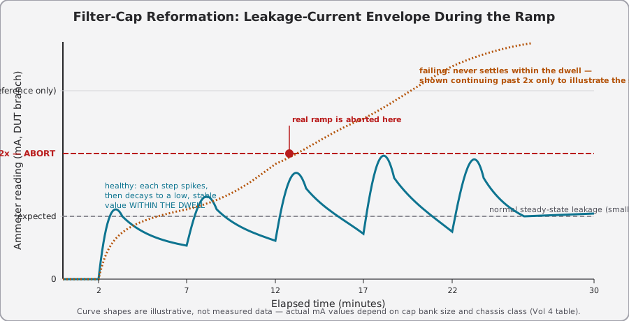
Detecting a dry or fully open cap. Not every long-stored electrolytic reforms — some have lost enough electrolyte to volume that there is nothing left to reform. A dry/open cap shows as: near-zero capacitance on a bench meter before power-up (a useful pre-screen if you have a cap meter handy), and during the ramp, no filtering effect at all — B+ ripple stays high and a scope on the DC rail (isolated per Vol 3 §One-Hand Rule and §Isolation) shows uncollapsed AC ripple riding the DC even at full voltage. A dry cap does not typically cause a current-watch excursion by itself; it fails quiet, not loud. Confirm capacitance directly once the chassis is de-energized again.
Note — Reformation happening as a side effect of this power-up procedure is convenient but not a substitute for a controlled reform-and-log procedure when you specifically want a pass/fail number on a given capacitor or a batch of pulls. If a current-watch excursion during this ramp makes you suspicious of one specific can rather than the whole chassis, pull it and run it through Vol 5’s standalone reformation bench procedure, which uses a series limiting resistor and logs the actual leakage-current curve in mA over time — this volume’s ramp is chassis-level triage, not a per-component lab test.
4.5 The 30-Minute Slow-Ramp Protocol
The core move: bring the DUT’s supply voltage up from 0 V to full line voltage in discrete steps, holding (dwelling) at each step long enough to observe the current settle, watching the panel meter (switched to CURRENT for the dwell) closely. Thirty minutes total is the baseline for a medium chassis (a table radio or a small amplifier); larger or smaller chassis scale the total time — see the table below.
Note — one meter, two functions. The 1653A’s panel meter is a single 2-inch analog movement, switched between VOLTS (0–150 Vac) and CURRENT (0–2 A) by a front-panel selector — see Vol 2 §Metering Circuits for how the movement itself works. You cannot read output voltage and output current at the same time on this unit. The workflow below is written around that constraint: set the target voltage with the meter in VOLTS, then switch to CURRENT to watch the dwell, switching back to VOLTS only to confirm the next step’s target. If you want continuous, simultaneous voltage-and-current visibility, add a dim-bulb tester (§The Dim-Bulb Tester as a Companion Tool below) or an external clamp/series ammeter in line with the DUT — the panel meter alone cannot give you both channels at once.
Setup, before the first volt goes on:
- Confirm the 1653A’s 3 A line (input) fuse and internal 3 A output fuse are intact — if either has ever blown, do not simply replace and proceed; the last session’s abort log (§Documentation and Logging) should say why it blew. There is no breaker to reset here — a blown fuse means a fuse gets replaced, not a button gets pushed.
- Confirm the 1653A’s own mains ground/earth is sound — a 3-wire cord with a good ground pin into a verified-grounded outlet. The isolation transformer breaks the DUT’s path to earth by design; it does not remove the 1653A’s own chassis from needing a solid ground.
- With nothing connected to the output receptacle yet, toggle the Function pushbutton through both positions and confirm the single panel meter responds on both VOLTS and AMPS — a meter that is stuck on one function, or that does not move at all, is a pre-flight failure in its own right; do not start a ramp you cannot read.
- Confirm the 1653A’s output knob is at 0 V — with the meter on VOLTS, verify 0 V there, not just knob position, before connecting the DUT.
- Connect the DUT to the 1653A’s single isolated output receptacle. Do not use an intermediate unswitched outlet strip — go straight to the 1653A.
- If using a series dim-bulb tester in line with the DUT (§The Dim-Bulb Tester as a Companion Tool below), confirm its bulb wattage is appropriate for the DUT’s expected load before starting.
- Turn the DUT’s own power switch ON. The DUT is now sitting at 0 V from the 1653A — this is the baseline state you climb from.
The ramp, step by step (medium-chassis baseline):
Table 9 — The ramp, step by step (medium-chassis baseline):
| Step | Target voltage | % of 120 Vac line | Dwell | Watch for |
|---|---|---|---|---|
| 0 | 0 V | 0% | 1–2 min | Confirm DUT pilot lamp/filaments do NOT light yet if line-cord-fed filament string expects real voltage; establish ammeter zero |
| 1 | ~30 V | 25% | 5 min | Inrush spike then settle within ~30 s; filament string starts to glow dim orange on tube sets |
| 2 | ~60 V | 50% | 5 min | Current should track roughly proportional to step 1’s settled value, not spike disproportionately |
| 3 | ~90 V | 75% | 5 min | B+ rectifier starts conducting meaningfully on most designs; watch for any new current step-change |
| 4 | ~108 V | 90% | 5 min | Near-normal operating condition; this is where a marginal filter cap often reveals itself |
| 5 | 120 V | 100% | ≥8 min hold | Full operating voltage; confirm current is stable (not still trending) before declaring the ramp complete |
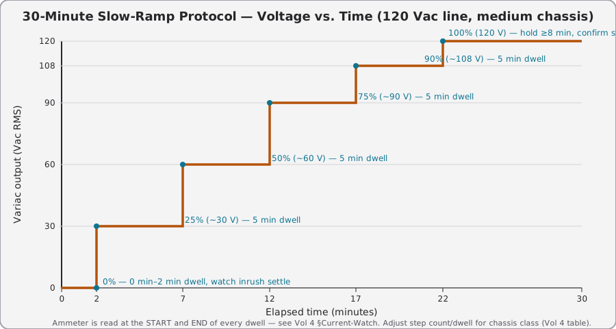
At every step transition, with the meter switched to VOLTS, turn the 1653A’s voltage knob smoothly to the new target — do not slam it. Once the target voltage is confirmed, switch the meter to CURRENT and then stop turning and watch it for the first 15–30 seconds before doing anything else. Most abort-worthy events happen in that first window after a step change, not mid-dwell. Switch back to VOLTS only to confirm the next step’s target.
4.5.1 Ramp Profile by Chassis Size
Scale the baseline above by chassis class. Bigger iron and bigger filter banks need longer dwells (more capacitance to reform, more thermal mass to bring up gently); smaller chassis can move faster.
Table 10 — Ramp Profile by Chassis Size
| Chassis class | Total ramp time | Step count | Dwell per step | Notes |
|---|---|---|---|---|
| Small (AA5-class table radio, small transistor-tube hybrid) | 15–20 min | 4 steps (0/33/66/100%) | 3–4 min | Small filter caps (typically ≤40 µF total), less thermal mass |
| Medium (console radio, small guitar/hi-fi amp) | 25–30 min | 5–6 steps | 5 min | Baseline table above |
| Large (console TV chassis, larger tube amp) | 35–45 min | 6–7 steps | 5–7 min | Larger filter banks, CRT high-voltage section adds its own inrush at the last steps — see Vol 3 §X-Ray Emission before this chassis class is ever run at full voltage unattended |
| Transmitter / PA stage | 45–60 min, or longer | 7+ steps, finer near top | 5–10 min, longer near 100% | Large plate-supply filter caps and often a plate transformer with significant idle draw; consider running the final approach to 100% in 5% increments rather than one 90→100% jump |
Note — These are workflow defaults, not physical constants. If the chassis-out inspection in §Chassis-Out Inspection turned up risk factors (rust on the transformer, damp storage history, an unusually large replacement filter cap of unknown age), slow the ramp down a class — treat a medium chassis like a large one. There is no penalty for being slower than the table; there is a real penalty for being faster.
4.6 Current-Watch: Reading the Ammeter
The 1653A’s panel meter, switched to CURRENT, is the single most important instrument in this entire procedure — more so than your eyes or nose, because it reacts faster than either. It is one dual-purpose analog movement, not two separate meters (§The 30-Minute Slow-Ramp Protocol above) — read Vol 2 §Metering Circuits for how the movement itself works; this section is about what the pattern of current readings tells you once the meter is switched over.
                    CURRENT-WATCH TRIAGE
                    (read at every step + continuously during dwell)

        ┌─────────────────────────────────────────┐
        │   Ammeter reading at/after a step change  │
        └───────────────────┬───────────────────────┘
                             │
              ┌──────────────┼──────────────┐
              │              │              │
       small inrush   sudden HIGH current   current climbs
       then settles   at LOW voltage        slowly, never
       within ~30s    (early ramp steps)    fully settles
              │              │              │
              ▼              ▼              ▼
          ┌───────┐   ┌────────────────┐  ┌───────────────────┐
          │NORMAL │   │ shorted xfmr OR │  │ leaky/reforming cap│
          │continue│  │ dead short in   │  │ not yet healed —   │
          │ ramp  │   │ the DUT wiring  │  │ still within normal│
          └───────┘   │                 │  │ envelope if trend  │
                       │  ABORT NOW      │  │ is DOWNWARD        │
                       │  (see Abort     │  └─────────┬──────────┘
                       │   Criteria)     │            │
                       └─────────────────┘   ┌────────┴────────┐
                                              │                 │
                                        trending DOWN     trending UP
                                        step over step     step over step
                                              │                 │
                                              ▼                 ▼
                                        ┌───────────┐   ┌───────────────┐
                                        │ CONTINUE — │   │ ABORT — this  │
                                        │ this is    │   │ is a failing  │
                                        │ reform in  │   │ cap, not a    │
                                        │ progress   │   │ reforming one │
                                        └───────────┘   └───────────────┘
4.6.1 Runaway-Pattern Triage Matrix
Table 11 — Runaway-Pattern Triage Matrix
| Symptom | Likely cause | Action |
|---|---|---|
| Small inrush spike at each step change, settles within ~30 s, magnitude roughly proportional to voltage | Normal — filament warm-up + filter cap charge current | Continue the ramp on schedule |
| Current spikes then decays to a low, stable settled value within each step’s dwell — even if a higher-voltage step’s peak exceeds the previous step’s peak | Filter cap(s) reforming — oxide layer healing per §Capacitor Reformation Theory (a higher-voltage step legitimately spikes higher; what matters is that it settles) | Continue, but hold the dwell until it visibly settles before advancing; do not rush a reforming cap |
| Current does not settle within the dwell, and/or the settled value itself trends upward step over step | A cap is failing, not reforming — genuine dielectric breakdown | Abort — see §Abort Criteria; pull and bench-test the suspect cap per Vol 5 |
| Sudden high current at a LOW voltage step (early in the ramp, well before full voltage) | Shorted power transformer winding, or a dead short elsewhere in the DUT (bare wire to chassis, shorted rectifier) | Abort immediately — this is not a reforming pattern at any voltage |
| Current pegs the meter or blows the 1653A’s internal 3 A output fuse at any step | Hard short | Abort immediately; do not attempt to “push through” |
| Current reads essentially zero at all steps, DUT pilot lamp/tube filaments never light | Open circuit upstream — blown fuse, open power switch contact, open primary winding, or (rarely) an open filament string | Not a safety abort, but a functional fault — de-energize and trace with the DUT fully off before re-attempting |
| Current is normal, but a specific stage’s B+ later reads wrong at spot-check | Likely a leaky coupling cap or drifted bias resistor, not a ramp-detectable fault | See §Post-Ramp Voltage Spot-Checks — this is a downstream diagnostic issue, not a ramp abort |
⚠ Danger — “Current that won’t settle” and “current that’s climbing” look similar on a quick glance at the needle but mean opposite things for how urgently you act. A cap that is reforming but slow to settle is not an emergency — hold the dwell longer. A cap that is genuinely failing can look the same in the first ten seconds and only reveals itself once the dwell should have settled and hasn’t, or once the settled value at the next step is higher than the settled value at the last one. This is why you watch whether the reading actually settles within the dwell and compare settled values step to step — not a single instantaneous expected-current number, and not the transient peak alone — see the triage matrix above.
4.7 Abort Criteria
Any one of the following is an immediate abort — return the 1653A’s voltage knob to 0 V, then switch the DUT off, then unplug. In that order: kill the source of energy before you touch anything else.
Table 12 — Abort Criteria
| Trigger | Threshold / description | Immediate action |
|---|---|---|
| Current excursion | Reading exceeds roughly 2× the expected value for that step (expected = last-known-good or manufacturer service-data draw) | Voltage to 0, DUT off, unplug |
| Any visible smoke | From any component — cap, resistor, transformer, wiring | Voltage to 0, DUT off, unplug, ventilate the area |
| Any audible arcing or sizzle | A distinct crackle/snap sound, not the normal faint hum of a transformer | Voltage to 0, DUT off, unplug |
| Hot-to-touch component that should not be | Any resistor, cap, or wire hot enough to be uncomfortable to a light finger-tap test within the first several minutes | Voltage to 0, DUT off, unplug, allow to cool before further handling |
| Ozone or burning smell | Sharp/acrid smell distinct from normal warm-dust smell of a first power-up | Voltage to 0, DUT off, unplug |
| Meter pegs or a fuse blows | Ammeter needle (with the meter switched to AMPS) drives past full scale, or the 1653A’s internal 3 A output fuse blows (not a deliberate test) | Do not simply replace the fuse and continue — this indicates a real overcurrent fault in the DUT; investigate before any further power-up attempt |
        ABORT FLOW
        ┌───────────────────────────────┐
        │ Any abort trigger observed?   │
        └───────────────┬────────────────┘
                         │ YES
                         ▼
        ┌───────────────────────────────┐
        │ 1. Variac knob to 0 V          │
        │    (kill the source FIRST)    │
        └───────────────┬────────────────┘
                         ▼
        ┌───────────────────────────────┐
        │ 2. DUT power switch OFF        │
        └───────────────┬────────────────┘
                         ▼
        ┌───────────────────────────────┐
        │ 3. Unplug DUT from 1653A       │
        │    output receptacle          │
        └───────────────┬────────────────┘
                         ▼
        ┌───────────────────────────────┐
        │ 4. Let filter caps discharge   │
        │    (minutes, not seconds —     │
        │    see Vol 3 One-Hand Rule)   │
        └───────────────┬────────────────┘
                         ▼
        ┌───────────────────────────────┐
        │ 5. Diagnose cold, chassis out  │
        │    (back to §Chassis-Out       │
        │    Inspection with new info)  │
        └───────────────────────────────┘
⚠ Danger — Do not chase an abort-triggering fault by turning the voltage knob down slightly and continuing — “back it off a little and see if it stabilizes” is how a marginal fault becomes a catastrophic one on the next attempt. Full abort, full cool-down, full re-diagnosis with the chassis cold and the caps discharged, every time.
When to stop and call it vs. push through. A single reforming cap that settles slower than expected but is settling (downward trend, matrix row 2 above) is worth patience — hold the dwell, even double it. A cap that is climbing (matrix row 3) is never worth pushing through; pull it and replace it or send it to Vol 5’s bench reform procedure where a series limiting resistor caps the worst-case current. If you find yourself aborting the same chassis on the same symptom twice in a row after a cooldown, that is your signal the chassis needs component-level repair before another ramp attempt — the workflow is not designed to be repeated indefinitely against the same unresolved fault.
4.8 Post-Ramp Voltage Spot-Checks
Once the ramp completes at full voltage with a settled ammeter reading, the DUT is running, but “running” and “correct” are not the same claim. Spot-check DC voltages against the schematic’s stated values (typical tolerance ±10–20% for a 60+ year old design, wider if line voltage itself has drifted from the design-era nominal — see Vol 5 §Brown-Out Simulation for testing the other direction).
Use an isolated meter reference — because the 1653A’s isolation transformer has already broken the DUT’s galvanic path to earth (Vol 3 §Isolation), a scope or DMM ground lead clipped to the DUT chassis is now safe to reference for measurement purposes only (this does not make the chassis safe to touch with bare skin — see Vol 3 §One-Hand Rule; a floating chassis can still carry lethal voltage relative to true earth even though it will not trip a breaker).
Table 13 — Post-Ramp Voltage Spot-Checks
| Chassis class | Typical spot-check points | What “normal” looks like |
|---|---|---|
| Small radio (AA5-class) | B+ at the filter cap output, plate voltage at the output tube, filament string voltage | B+ typically 90–130 Vdc on a transformerless set fed from the 1653A’s isolated 120 Vac; filament string should read close to rated total (e.g., ~120 V across a series string) |
| Console radio / small amp | B+ at first filter cap, B+ at last (most-filtered) cap, screen voltage on output tube(s), bias voltage at cathode or fixed-bias supply | Multi-stage RC-filtered supplies should show a voltage drop stage to stage (first cap highest, last cap lowest by the dropping-resistor IR loss) |
| TV chassis | Low-voltage B+ rail(s), boost/high-voltage B+ if separately accessible, CRT filament voltage | Confirm against service data; do NOT probe the CRT anode connection itself with a general-purpose meter — that node needs a purpose-rated high-voltage probe, see Vol 3 §kV-Rated Probe Ratings |
| Audio amplifier (guitar/hi-fi) | B+ at power tube plates, screen voltage, bias voltage (fixed-bias designs), speaker-output DC offset (should be ~0 V, any real DC offset indicates an output-stage or transformer fault) | Plate voltages typically within 10–15% of schematic spec once line voltage and cap ESR/age are accounted for |
| Transmitter / PA | Plate supply B+, screen supply, bias supply, grid current (if metered) | Compare against the equipment’s own manual — transmitter plate supplies run high enough that Vol 3’s kV-probe-rating table is mandatory reading before this spot-check |
⚠ Danger — On any chassis with a CRT (television, oscilloscope), the anode connection carries several kilovolts and the CRT itself can emit soft X-rays at elevated anode voltages on some designs — see Vol 3 §X-Ray Emission from High-Voltage CRTs. This spot-check stage does not include probing the anode cap; that is specialized-tool territory, not a general power-up step.
If every spot-check lands within a reasonable band of schematic spec, the chassis has passed power-up. If one stage is off while the rest are fine, that is a targeted repair problem (see §Chassis-Out Inspection for the component classes most likely responsible — a leaky coupling cap or a drifted resistor, most commonly), not a reason to distrust the whole ramp procedure.
4.9 The Dim-Bulb Tester as a Companion Tool
A dim-bulb tester is a household incandescent lamp wired in series with the DUT’s line input — the oldest, cheapest current limiter in the hobby. It is not a substitute for the 1653A’s slow-ramp protocol; it is a complementary layer that can run simultaneously with it.
How it works. The lamp’s cold-filament resistance is low, so a genuine short in the DUT still lets enough initial current through to light the bulb brightly — a fast, obvious visual abort signal, faster than reading a needle. As the DUT draws normal current, the lamp glows dim or not at all (a properly operating chassis’s steady-state draw is well under what makes a 60–100 W bulb glow brightly). The lamp’s resistance also rises with its own filament temperature, which means it self-limits: more DUT current draw pushes more voltage drop across the lamp and proportionally less across the DUT, a passive negative feedback loop that a plain series resistor does not give you.
Combining it with the 1653A. Wire the dim-bulb tester between the 1653A’s output receptacle and the DUT. You now have two independent layers: the 1653A gives you controlled, metered, slow voltage climb with galvanic isolation and an internal 3 A output fuse; the dim-bulb tester gives you instantaneous, fail-safe current limiting that reacts faster than a human reading an ammeter can. On a chassis you have real reason to distrust (bad smell at chassis-out inspection, prior known fault, unknown full history), running both together is standard practice — the lamp catches the sub-second events, the 1653A’s slow ramp and metered ammeter catch the slower reforming/drifting events.
Where a dim-bulb tester falls short compared to the 1653A alone. A lamp in series does not isolate the DUT chassis from earth — it is just a resistor, wired hot-side, in an otherwise ordinary line connection. If the chassis you are testing has a floating/hot-chassis topology (Vol 3 §Floating-Chassis Sources), a dim-bulb tester alone gives you no isolation protection at all. The 1653A’s isolation transformer is doing real safety work that a lamp cannot substitute for. Use the lamp as an addition to the 1653A’s protection, never as a stand-alone replacement for it on a floating-chassis DUT.
Table 14 — The Dim-Bulb Tester as a Companion Tool
| Aspect | 1653A slow-ramp alone | Dim-bulb tester alone | Both together |
|---|---|---|---|
| Voltage control | Full 0–150 V, metered, steppable | None — full line voltage from the first instant | 1653A controls voltage; lamp adds current limiting at every step |
| Current limiting | Only via operator switching the panel meter to CURRENT, watching it, and backing off | Automatic, passive, sub-second reaction to a short | Redundant — automatic AND metered |
| Galvanic isolation | Yes (built-in 1:1 transformer) | No | Yes, via the 1653A |
| Output overcurrent protection | Yes (internal 3 A output fuse, plus the 3 A line/input fuse) | No (relies on the DUT’s own fuse only) | Yes, via the 1653A |
| Best for | Reforming caps, general power-up, any chassis where you want a metered, steppable ramp | A quick, cheap sanity check on chassis you already trust reasonably well | Chassis with unknown history, prior fault indications, or heavy chassis-out inspection findings |
4.10 Worked Example: A Full Ramp Session
The abstract tables above read differently once attached to a specific chassis. Below is a representative walkthrough for a medium-class chassis — a five-tube console radio with a transformer-based B+ supply and two can-style filter electrolytics, unpowered roughly fifteen years, chassis-out inspection clean aside from mild dust and one axial cap with a cracked-but-not-leaking paper wrap.
Pre-flight and chassis-out. Line cord replaced (original cloth cord was stiff but not cracked — replaced anyway per house policy of not trusting 60+ year old cord insulation). No bulging cans, no tar smell from the transformer, no bare wire found. The one cracked-wrap axial cap is left in place for now (not leaking, not near a critical bias node) with a note to revisit if the spot-check on that stage looks off.
Ramp log (illustrative — actual mA values vary by chassis; meter switched to VOLTS to set each target, then to CURRENT for the reading logged below):
Table 15 — Worked Example: A Full Ramp Session
| Time | Step | Target V | Meter reading (A, switched to CURRENT) | Notes |
|---|---|---|---|---|
| 0:00 | 0 | 0 V | 0 mA | Baseline, DUT switch ON, 1653A at 0 V |
| 0:02 | 1 | 30 V | 40 mA → settles to 15 mA by 0:04 | Filament string starts to glow faint orange; normal inrush-and-settle |
| 0:07 | 2 | 60 V | 55 mA → settles to 30 mA by 0:09 | Proportional climb from step 1, no red flags |
| 0:12 | 3 | 90 V | 90 mA → settles to 48 mA by 0:15 | Rectifier tube visibly conducting (faint blue glow inside envelope, normal for this tube type); current still tracking proportionally |
| 0:17 | 4 | 108 V | 105 mA → settles to 58 mA by 0:20 | Settle time slightly longer than prior steps — attributed to the older filter cap continuing to reform; held the dwell an extra 2 min past the standard 5 |
| 0:24 | 5 | 120 V | 118 mA → settles to 65 mA by 0:30 | Full voltage, current stable and flat for the last 4 minutes of the hold — ramp declared complete |
Total elapsed time: 30 minutes, within the medium-chassis baseline. The step-4 settle time running long matches the classic reforming signature from §Capacitor Reformation Theory — current spikes then decays to a low, stable settled value within the dwell at every step, just slower to get there at step 4 (the settled values themselves climb gently step to step, 15→30→48→58→65 mA, which tracks the rising applied voltage and is expected) — not an abort trigger, just a note in the log.
Post-ramp spot-check. B+ at the first filter cap read within 8% of the schematic’s stated value; B+ at the second (more-filtered) cap read within 12% — both inside the expected band for a 60+ year old design on today’s line voltage. The stage fed by the cracked-wrap axial cap read a plate voltage about 20% low compared to schematic — outside the comfortable band. That cap is now the leading suspect and gets pulled for out-of-circuit leakage testing rather than trusted further; the ramp itself is complete and successful, the follow-up repair is a separate task.
4.11 Documentation and Logging
A ramp session is worth logging in real time, not reconstructed from memory afterward — the whole value of current-watch triage (§Current-Watch above) depends on comparing this step’s reading against the previous step’s, and that comparison is only reliable if both numbers were actually written down.
Minimum fields worth capturing per session, whether in a paper bench notebook or a spreadsheet:
Table 16 — Minimum fields worth capturing per session, whether in a paper bench notebook or a spreadsheet
| Field | Why it matters |
|---|---|
| Chassis identification (make/model/serial if present) | Ties the log to a specific unit for future reference |
| Chassis-out inspection findings | Documents what was checked and what was found/replaced before power-up — the record that justifies “this was safe to ramp” |
| Ramp date and total elapsed time | Establishes a baseline for comparison if the same chassis is ever re-ramped after long storage again |
| Ammeter reading at start AND end of every dwell | The actual triage data — a single reading per step throws away the settle-time information that distinguishes reforming from failing |
| Any dwell extended beyond standard, and why | Documents judgment calls for future reference |
| Post-ramp spot-check voltages against schematic spec | Closes the loop — confirms the ramp produced a working supply, not just “current looked fine” |
| Any abort events, even resolved ones | A chassis that aborted once and was later fixed and re-ramped successfully still has a history worth keeping |
This log is also the input to Vol 5’s calibration/verification cycle if the 1653A’s own meter is ever being cross-checked against a bench DMM — a history of plausible, schematic-matching readings across many sessions is itself a weak but useful confirmation the 1653A’s metering has not drifted.
Sources
Facts in this volume were checked against the following before writing:
- 1653A published specifications (output 0–150 Vac continuously variable from a 120 Vac/60 Hz, 300 VA input; 2 A continuous 0–130 V; single isolated output receptacle; output-isolation leakage < 0.1 mA at 25 °C/50% RH; overload protection; single dual-function meter): the B&K Precision 1653A/1655A instruction manual (FEATURES p.3, SPECIFICATIONS p.4) is the authoritative source for the Model 1653A column specifically, cross-checked against the DigiKey listing and independent datasheet summaries. The 1653A uses a 3 A line (input) fuse plus an internal 3 A fuse protecting the output at low voltages where a fault might not blow the input fuse — not a resettable circuit breaker. (The 1655A, the two-outlet sibling unit, is the one with the 3.15 A resettable circuit breaker, a 3-1/4-inch multi-function meter with extra current/leakage scales, a power-line leakage-test probe, and a soldering-iron temperature-control outlet — none of those four features are on the 1653A; an earlier draft of this dive conflated the two models and misattributed them, corrected as of this revision.) The 1653A’s single panel meter is a 2-inch movement, overrange-protected, ±5% of full scale (calibrated at 120 Vac), selected between VOLTS (0–150 V) and AMPS (0–2 A) by a front-panel Function pushbutton — never both at once. None of these sources describe a ground-fault interrupter of any kind on this unit. The 1653A has no GFCI, no GFCI TEST/RESET button, and no ground-fault trip function — an earlier draft of this dive incorrectly assumed one was present, and that assumption is corrected as of this revision. The unit’s protection is galvanic isolation (breaking the DUT’s return path to earth) plus fault-current-limiting fuses, not active ground-fault sensing. An operator who specifically wants active ground-fault protection needs a separate GFCI on the 1653A’s mains input, upstream of the isolation transformer — with the caveat that a GFCI placed on the isolated output side instead would not see a fault on the floating secondary at all (Vol 3 §Isolation vs. GFCI).
- Aluminum electrolytic capacitor dielectric reformation (oxide-layer breakdown during unpowered storage, self-healing regrowth under applied voltage, stepped-voltage reforming practice, leakage-current decay as the healing signature): cross-checked against VFD-industry reforming guidance (KEB America “VFD Storage and Capacitor Reforming,” Industrial Monitor Direct capacitor-reforming guides, Specap Inc. “How to Reform Old Electrolytic Capacitors Safely”) — these describe the identical stepped-voltage-ramp reforming practice (10/25/50/75/90/100% with holds, watching leakage current decrease at each step) independently of the tube-radio hobby literature, which converges on the same physics from a different industry. The specific step percentages and dwell times used in this volume’s ramp table are this volume’s own workflow synthesis, not a quoted industry standard — flagged as a design choice, not a verified external number.
- Wax-paper/“black beauty” coupling capacitor failure mode (DC leakage causing downstream bias drift, distinct from electrolytic bulk-capacitance failure, does not reform): general tube-electronics restoration knowledge; treated in this volume as qualitative guidance, no specific numeric leakage threshold asserted.
- X-ray emission and kV-probe-rating cross-references: not re-derived here; this volume points to Vol 3 where those numbers are sourced and owned.
- PCB transformer/capacitor dating (pre-1979 TSCA ban): cross-referenced to Vol 3’s hazardous-materials catalog; not re-verified independently in this volume — see Vol 3’s own Sources section.