B&K 1653A Variac · Volume 5
B&K 1653A Variac — Vol 5: Operating Procedures & Advanced Techniques
The operator's reference for day-to-day use of the 1653A — front-panel discipline, brown-out margin testing, bench cap reformation, current-limiting technique, meter self-verification, and self-care for the instrument itself.
5.1 Scope of This Volume
Vol 4 covers the canonical unknown-chassis power-up workflow — the 30-minute slow ramp, current-watch triage, abort criteria. This volume assumes the DUT is already known-good or already brought up per Vol 4, and covers everything else the 1653A gets used for on a working bench: routine session discipline, deliberately degrading the line to check margin, a dedicated lab-grade capacitor reformation procedure for a pulled part (not an in-chassis ramp), using the 1653A itself as a current-limiting element, checking the 1653A’s own meters against a real standard, and keeping the instrument itself healthy. Read Vol 1 first if you have not — it carries the unknown-chassis decision tree this volume assumes you already applied.
5.2 Front-Panel Walkthrough & Pre-Session Routine
5.2.1 Controls and What Each One Does
Table 1 — Controls and What Each One Does
| Control | Function | Set/verify before energizing |
|---|---|---|
| Power / line switch | Connects mains to the primary of the brush autotransformer | OFF, then confirm the voltage-adjust knob is at 0 V before switching ON |
| Voltage-adjust knob | Rotary drive on the brush arm; sweeps 0–150 Vac at the output tap | Start every session at the 0 V mechanical stop (§5.2) |
| Meter-select (V/A) switch | Routes the single front-panel movement between the 0–150 Vac scale and the 0–2 A scale | Select V first — you want to watch voltage climb during ramp-up, then flip to A once the DUT is loaded |
| Fused output receptacle(s) | Isolated, metered AC output, protected by a fixed internal 3A output fuse (in addition to the 3A line fuse ahead of it) | Confirm nothing is plugged in before power-up; the output fuse rating is fixed at 3A — if a DUT needs a tighter current ceiling, add external current limiting (dim-bulb/series-R, §5.5) rather than expecting the unit’s own fuse to be re-rated per DUT |
| Chassis/ground terminal | Bonds the enclosure and the isolated-secondary reference point per the unit’s internal grounding scheme | See Vol 3 §earth-bonding-when-working-on-an-isolated-DUT before you decide whether to bond the DUT chassis here |
Note — B&K’s own instruction manual for the 1653A documents a single 2 in. analog movement, switched between a 0–150 Vac scale and a 0–2 A scale by the alternate-action Function pushbutton — not two independent voltmeter and ammeter movements. This volume treats the panel meter as one switched movement. (The larger sibling 1655A carries a 3-1/4 in. multi-function movement with extra current/leakage scales — that spec belongs to the 1655A, not this unit.)
5.2.2 The Meter Scale — 0–150 V, Overrange-Protected Movement
The panel VOLTS scale reads 0–150 Vac, matching the AC VOLTS control’s full 0–150 Vac output span (120 Vac in). B&K’s data sheet describes the metering as “overrange protected” — that refers to the meter movement itself: it tolerates being driven past full-scale deflection (a moment of over-travel, a transient) without damage to the needle or coil. It is not a claim that any part of the scale sits below the instrument’s true range — there is no dead band, and the printed scale runs the full 0–150 V span end to end. For everyday tube-gear work at or near line voltage (105–130 V) this is comfortably mid-scale and easy to read; the only place it gets harder is near the very top of the range on a boost test, where reading resolution on any analog scale naturally coarsens near full deflection.
5.2.3 Reading the Meter Honestly
Published meter accuracy is ±5% of full scale, on both the V and A functions. Full scale is 150 Vac / 2 A, so the absolute error budget is constant across the dial — roughly ±7.5 V and ±0.1 A — not 5% of whatever the needle happens to read. That has a nasty consequence at the low end:
Table 2 — Published meter accuracy is ±5% of full scale, on both the V and A functions. Full scale is 150 Vac / 2 A, so the absolute error budget is constant across the dial — roughly ±7.5 V and ±0.1 A — not 5% of whatever the needle happens to read. That has a nasty consequence at the low end
| Actual reading | ±5%-of-FS absolute error | Error as % of THIS reading |
|---|---|---|
| 150 V (full scale) | ±7.5 V | ±5.0% |
| 75 V (mid-scale) | ±7.5 V | ±10.0% |
| 15 V (near brown-out floor, §5.3) | ±7.5 V | ±50.0% |
| 2 A (full scale) | ±0.1 A | ±5.0% |
| 0.2 A (light DUT load) | ±0.1 A | ±50.0% |
Note — Never trust the panel meter for a precision reading near the bottom of its scale. The brown-out procedure below (§5.3) targets 95 V and 85 V — both comfortably mid-scale, so the panel meter is fine for setting the target voltage there. The cap-reformation procedure (§5.4) and any light-load current reading are a different story — bring a DMM.
5.2.4 Typical Starting Points by DUT Class
Vol 4 owns the full ramp protocol (step count, dwell time, per-step abort criteria) by chassis size. This table is narrower — just the knob position and expected settled-current ballpark you should see once a known-healthy unit of each class is sitting at full line, useful as a sanity check before you trust the panel ammeter for anything quantitative (§5.6) or set up a brown-out run (§5.3).
Table 3 — Typical Starting Points by DUT Class
| DUT class | Typical settled current at 120 V | Typical starting knob position for a routine (non-first) power-up | Notes |
|---|---|---|---|
| Small AC/DC “All-American Five” radio | 0.1–0.3 A | Full line directly (once known-healthy — see Vol 3’s floating-chassis warning before touching it at all) | Low current means the panel ammeter’s ±0.1 A absolute error band is a large fraction of the reading — verify with a DMM if the exact number matters |
| Large console radio / multi-tube receiver | 0.3–0.8 A | Full line directly once known-healthy | Comfortably mid-scale on the panel ammeter |
| Black-and-white or color CRT television | 0.5–1.5 A (varies hugely by chassis generation and CRT size) | Full line directly once known-healthy; ramp again after any service work | Approaches the 2 A continuous rating on larger color chassis — watch headroom, especially during a brown-out run (§5.3) |
| Tube audio amplifier | 0.3–1.0 A, output-stage-dependent | Full line directly once known-healthy | Class AB idle current is a useful individual baseline beyond what the panel meter alone tells you |
| Transmitter PA / high-power tube gear | Can exceed 2 A depending on stage | Do not assume the 1653A alone is adequate — check against its 2 A continuous rating before committing this instrument to the job | May require a larger external Variac / a dedicated PA power sequencer instead of the 1653A |
Note — These are ballpark figures for orientation, not spec-grade numbers for any specific chassis — every real DUT gets its own logged baseline in its own project’s
DEVELOPMENT.md.
5.2.5 Pre-Session Checklist
Run this before every session, not just the first one of the day — a knob left mid-travel from the last user, or a blown output fuse that silently defeats protection, are the two failures that bite hardest.
Table 4 — Pre-Session Checklist
| # | Step | Why |
|---|---|---|
| 1 | Line switch OFF | Baseline state before touching anything |
| 2 | Voltage-adjust knob to the 0 V mechanical stop/detent | Never energize a DUT starting above 0 V — Vol 4’s ramp protocol depends on starting cold |
| 3 | Confirm nothing is plugged into the output receptacle | A leftover DUT from the last session gets full mains the instant you power up otherwise |
| 4 | Power ON, confirm the pilot light and meter come up live (meter selector on V, knob still at 0) | Confirms the unit itself is functioning before you commit a DUT to it |
| 5 | Visually check the output fuse (or swap in a known-good one if history is unknown) | A blown fuse silently defeats the “fused output” safety line without failing anything else |
| 6 | Plug in the DUT, meter selector to A | You want current visible from the first volt of ramp |
| 7 | Begin the Vol 4 ramp (or the brown-out / reform procedure below, as applicable) | — |
5.2.6 Isolation & Fuse Protection — What the 1653A Actually Provides
The 1653A’s protection stack is a built-in 1:1 isolation transformer (mains-to-output leakage <0.1 mA per B&K’s instruction manual) plus a fixed 3A fuse on the line input and a second, internal fixed 3A fuse on the isolated output. There is no resettable circuit breaker — an overload blows a fuse, which you replace, it does not reset — and the unit contains no ground-fault circuit of any kind: B&K’s manual documents neither a TEST/RESET control nor a ground-fault trip spec anywhere in the 1653A’s front-panel description. (A resettable 3.15A breaker is an explicitly 1655A-only feature in that manual and does not apply to the 1653A this hub covers.)
Isolation is a different, real safety property from ground-fault interruption — it floats the output relative to earth, which is what makes it safe to probe a “hot chassis” AC/DC set without instantly shorting through a scope ground (see Vol 3) — but the 1653A does not sense or interrupt fault current itself. Its two fixed 3A fuses are the only overcurrent protection this instrument provides.
⚠ Danger — Do not assume this instrument gives you ground-fault protection. It gives you isolation and two fixed 3A fuses — nothing more. Confirm both fuses are intact before every session (§5.1); a blown output fuse silently defeats the “fused output” safety line without failing anything else.
5.3 Brown-Out / Line-Sag Simulation
5.3.1 Why Deliberately Sag the Line
Two different audiences want this:
- Margin-testing a supply or piece of gear you’re validating — does a switch-mode brick, a linear regulator, or a relay-driven circuit still function correctly as the input voltage sags, and does it fail gracefully (clean shutdown / UVLO) rather than ugly (brownout-induced misbehavior, partial operation, latch-up)?
- Marginal vintage tube gear — filament/heater voltage on tube equipment is itself sensitive to line voltage; a set that “mostly works” at full line can reveal hum, drift, or intermittent oscillation once the line sags a realistic amount, which is exactly the kind of fault a set sees in the field on an overloaded circuit or a long extension cord.
5.3.2 Where 95 V and 85 V Sit on the Real Voltage-Tolerance Ladder
ANSI C84.1 defines two service/utilization voltage ranges for a nominal 120 V system: Range A is ±5% (114–126 V), the range utilities are expected to stay inside routinely; Range B is roughly +6%/−13% (about 104–127 V at the utilization end), an infrequent-excursion range that’s still supposed to be tolerable. A utility-imposed “brownout” (a deliberate, temporary voltage reduction for load shedding) is commonly described as a 10–25% cut — 120 V × 0.90 = 108 V down to 120 V × 0.75 = 90 V.
Table 5 — Where 95 V and 85 V Sit on the Real Voltage-Tolerance Ladder
| Test point | % of 120 V nominal | Where it sits | What it’s testing for |
|---|---|---|---|
| 108 V | 90% | Inside a typical utility brownout | Realistic worst-normal-day sag |
| 95 V | ~79% | Beyond typical brownout, inside “how bad does it get before it’s dangerous” territory | Margin beyond ANSI Range B’s utilization floor — reveals UVLO thresholds, relay dropout, tube hum/drift |
| 85 V | ~71% | Well outside any normal utility excursion | Deliberate stress point — confirms how the DUT fails, not whether it operates normally here |
Note — 95 V and 85 V are stress/margin test points, not “normal” operating conditions to leave gear running at for extended periods. The goal is a controlled, monitored dip and recovery, not sustained low-voltage operation.
5.3.3 Tube-Gear-Specific Margin Effects
The 1653A’s isolation transformer is 1:1, so whatever sag you dial in on the primary side reaches the DUT’s own power transformer input directly — heater/filament winding and B+ winding sag together, proportionally. That has different failure signatures than a solid-state DUT’s brown-out behavior:
Table 6 — The 1653A's isolation transformer is 1:1, so whatever sag you dial in on the primary side reaches the DUT's own power transformer input directly — heater/filament winding and B+ winding sag together, proportionally. That has different failure signatures than a solid-state DUT's brown-out behavior
| Sag effect | Mechanism | What you’ll observe |
|---|---|---|
| Heater/filament under-run | Cathode runs cooler, electron emission drops | Softer, sometimes distorted or reduced output; in extreme cases, intermittent operation as emission margin runs out on a marginal tube |
| B+ sag | Plate/screen voltage drops with the transformer primary | Reduced output level, possible increased hum (less supply headroom to filter against), power-stage clipping point moves |
| Bias supply sag (if derived from the same transformer) | Grid bias shifts along with everything else | Can partially self-compensate (lower B+ and lower bias can track), or can misbehave if the bias supply has its own regulation the rest of the circuit lacks |
| Relay / contactor dropout | Electromechanical relays typically drop out somewhere around 60–80% of their rated pull-in voltage (generic relay-design range, not a per-unit spec) | A sag test that crosses a relay’s dropout point produces a hard, audible fault rather than a graceful degradation — useful data, but distinguish “found the dropout point” from “broke something” |
⚠ Danger — A sustained under-heated cathode (hours, not the few minutes of a margin test) is a separate, slower failure mode — cathode poisoning / reduced emission life from chronic under-run operation. A brief brown-out margin test does not meaningfully risk this; leaving a tube running underheated as a matter of habit does. Don’t conflate the two.
5.3.4 Procedure
- Bring the DUT up to full line (Vol 4 ramp, or already-healthy known gear) and let it stabilize.
- Note baseline current draw on the panel ammeter (§5.1 accuracy caveats apply — use a DMM in series if the DUT’s normal current puts you in the bottom third of the 2 A scale).
- Reduce the voltage-adjust knob smoothly to 108 V. Hold 2–5 minutes. Log behavior: hum, drift, dropout, current change.
- Reduce further to 95 V. Hold 2–5 minutes. Same log.
- If the test calls for it, reduce to 85 V. Hold briefly (1–2 minutes is usually enough to see a failure mode — this is stress, not soak). Log behavior.
- Return smoothly to full line. Confirm the DUT recovers cleanly (no latched fault state, no residual misbehavior).
⚠ Danger — Current draw does not fall in proportion to voltage for a constant-power load — it rises (I = P/V). A DUT drawing 1.5 A at 120 V pulling the same wattage at 85 V draws over 2.1 A, which is past the 1653A’s 2 A continuous rating. Watch the ammeter through the whole sag, not just at the target voltage — abort per Vol 4’s current-watch criteria if it climbs past expected.
Note — Do not brown-out test a DUT with unreformed or unknown-condition electrolytics. A cap that’s still healing its dielectric will show current behavior that has nothing to do with the DUT’s actual line-margin performance and will confound the test. Reform first (Vol 4’s in-chassis workflow, or §5.4 below for a pulled part), then margin-test.
Log brown-out results in this instrument’s own DEVELOPMENT.md (per-instrument), and in the specific project/DUT’s own development notes if the brown-out test was in service of validating that piece of gear — a Heathkit SP-2717A HVPS, for example, is exactly the kind of supply where a documented brown-out margin result belongs in its own project file, not buried here.
5.4 Long-Stored Capacitor Reformation — Dedicated Bench Procedure
Vol 4 covers cap reformation as a side effect of the in-chassis power-up ramp — you watch the ammeter climb-then-settle as filter caps heal, in place, as part of bringing up an unknown chassis. This section is a different, narrower thing: a pulled component (or a small isolated subassembly) on the bench, tested deliberately and in isolation, with a real pass/fail criterion and a logged reform curve — the kind of procedure you’d run before deciding whether a cap goes back into a restoration or into the scrap bin.
5.4.1 Setup
 MAINS ──► 1653A (0–150 V, isolated) ──► SERIES LIMIT RESISTOR R ──► CAP UNDER TEST
                                                                          │
                                                        DMM (µA/mA range, or a
                                                        DC microammeter) reads
LEAKAGE CURRENT in series- Series limit resistor R: sized so a fully-shorted cap doesn’t dump destructive current or exceed the resistor’s power rating. A common choice is a resistor that limits worst-case current (at full test voltage, cap treated as a dead short) to a few tens of milliamps — e.g. for a 450 V rated cap tested up to 450 V, a 10 kΩ / 5 W resistor limits a hard short to 45 mA (≈20 W briefly, well inside a 5 W resistor’s short-duration rating, but check the resistor’s pulse/surge rating, not just its steady-state wattage, if the short is expected to persist).
- Leakage read-out: the 1653A’s own panel ammeter is scaled 0–2 A and cannot usefully resolve microamp-to-low-milliamp leakage current — bring a DMM (or a dedicated microammeter) in series for this reading, not the panel meter.
- Isolation matters here specifically because the cap under test is handled directly on the bench, often with alligator clips and bare fingers nearby between voltage steps — the same isolation argument from Vol 3 applies, but doubly so because this is hands-on component-level work, not a chassis at arm’s length.
5.4.2 Stepped-Voltage Soak Schedule
Table 7 — Stepped-Voltage Soak Schedule
| Step | Target voltage | Typical dwell | Watch for |
|---|---|---|---|
| 1 | 10% of rated V | 15–30 min | Initial leakage current, should be visible but not alarming |
| 2 | 25% of rated V | 15–30 min | Leakage should be trending down from step 1’s level at the new voltage, not climbing |
| 3 | 50% of rated V | 30–60 min | This is where a genuinely bad cap usually reveals itself — leakage that won’t stop climbing |
| 4 | 75% of rated V | 30–60 min | Confirm the downward/flattening trend continues |
| 5 | 100% of rated V | 60+ min, or until leakage flattens | Final pass/fail read |
Note — Dwell times above are common bench practice, not a manufacturer-published standard — treat them as a starting point and extend any step where leakage is still visibly falling. The trend (falling → flat) matters far more than hitting a specific clock time.
5.4.3 Worked Example — Sizing R for a 450 V Electrolytic
Take a common vintage filter cap: 40 µF, rated 450 Vdc. Treat “cap fully shorted” as the worst case at full test voltage and size R so that worst case doesn’t exceed a safe current:
- Target worst-case current: pick something the resistor and the DMM/microammeter in series can both handle comfortably without the resistor overheating on a sustained short — a common choice is tens of milliamps, not hundreds.
- R = V / I_worst-case → at 450 V targeting ≤45 mA worst case: R = 450 V / 0.045 A ≈ 10 kΩ.
- Worst-case power in R during a sustained hard short: P = V²/R = 450² / 10,000 ≈ 20 W, briefly, while the fault persists. A 10 kΩ resistor rated for continuous 5 W can absorb this for the short window it takes to notice the fault and back off the voltage, but check its pulse/surge rating specifically if you expect the short to persist rather than being caught immediately — don’t rely on the steady-state wattage number alone for a fault condition.
- At the pass condition — leakage current settled to a low steady value, say under 1 mA — the drop across R is negligible (1 mA × 10 kΩ = 10 V out of 450 V), so the cap sees essentially the full step voltage once healed, which is the point.
5.4.4 Common Vintage Cap Ratings & Suggested Test-Voltage Steps
Table 8 — Common Vintage Cap Ratings & Suggested Test-Voltage Steps
| Common rating | Typical use | Suggested step voltages (10/25/50/75/100%) |
|---|---|---|
| 20–40 µF, 150 V | AC/DC “All-American Five” filter caps | 15 / 37.5 / 75 / 112.5 / 150 V |
| 20+20 µF (dual), 450 V | Console radio / early TV filter caps | 45 / 112.5 / 225 / 337.5 / 450 V |
| 40+40 µF (dual), 450 V | Larger console / amplifier filter caps | 45 / 112.5 / 225 / 337.5 / 450 V |
| 10–20 µF, 600 V | Higher-B+ transmitter or PA supplies | 60 / 150 / 300 / 450 / 600 V |
Note — These are common historical ratings for orientation when planning step voltages, not a claim about any specific cap you’re testing — always work from the rating printed on the part itself.
5.4.5 Reform-Curve Log Template
Table 9 — Reform-Curve Log Template
| Time (min) | Step voltage (V) | Leakage current | Notes |
|---|---|---|---|
| 0 | 10% | — | Initial contact, cold cap |
| 5 | 10% | ||
| 15 | 10% | ||
| 30 | 25% | step up | |
| … | … |
5.4.6 Pass / Fail
- Pass: leakage current at each step trends down and flattens within the dwell window; at 100% of rated voltage, leakage stabilizes at a low, steady value.
- Fail: leakage keeps climbing and does not flatten within a generously extended dwell, or the resistor gets hot enough to indicate a near-dead-short condition, or the cap shows physical signs (bulging, venting, heat, smell) at any step — abort immediately per Vol 4’s abort criteria, which apply here too.
Note — Bench folklore offers rule-of-thumb leakage targets (something on the order of a few hundredths of a milliamp per microfarad per volt of rated voltage, e.g. roughly single-digit milliamps for a 40 µF/450 V cap) — this is restoration-community practice, not a citable manufacturer or standards-body spec, and is flagged as such. The trend test (falling, then flat) is the reliable criterion; a specific numeric leakage target is a secondary sanity check at best.
Cross-ref: the dielectric-reformation theory — why a long-stored aluminum-electrolytic leaks and then heals as the oxide layer rebuilds — is covered once, in Vol 4’s cap-reform-theory section; this procedure is the deliberate, isolated-component application of that same physics.
5.5 Using the 1653A as a Current-Limiter
5.5.1 The Trick, and Its Limit
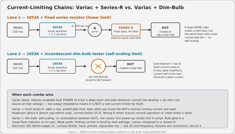
Turning the voltage-adjust knob down reduces available fault power (P = V·I), but the 1653A’s brush autotransformer plus 1:1 isolation transformer is a low-source-impedance chain — at whatever voltage the knob is set to, a dead short on the output can still pull close to the full current that chain can source at that voltage. The Variac alone is not a real current limiter. Adding a fixed series resistor between the 1653A’s output and the DUT turns it into one: the resistor drops more volts as fault current rises, giving the DUT a real ceiling.
5.5.2 Series-R vs. Dim-Bulb vs. Electronic Limit
Table 10 — Series-R vs. Dim-Bulb vs. Electronic Limit
| Method | Self-scaling? | Best for | Weakness |
|---|---|---|---|
| 1653A alone (voltage only) | No | Reducing available fault power, not limiting current | Dead short at any set voltage still pulls near-full available current |
| 1653A + fixed series R | No — R is picked once per test | Bench cap-reform soak (§5.4) where you know the expected current and want firm headroom above it | Wrong R either starves normal load or under-limits a hard short; must be recalculated per DUT |
| 1653A + incandescent dim-bulb tester | Yes — cold filament = low R, fault heats it, R rises, glow brightens | First power-up of an unknown chassis (pairs with Vol 4’s ramp) — no recalculation needed between DUTs | Limiting current is coarse, fixed by bulb wattage; not a precision, adjustable value |
| Electronic (DC bench-supply CC mode, e-fuse / foldback) | Yes, and precise/adjustable | Repeatable numeric current limits, DC rails downstream of a rectifier | AC-line-frequency electronic limiters are uncommon and add complexity; most tube-gear work stays with the dim-bulb + Variac combo for the AC side |
5.5.3 Worked Example — Sizing R for a Known DUT
A DUT is known to draw 100 mA at 120 V normally, and you want a firm ceiling around 300 mA if something goes wrong during a bench test (a repair-in-progress, say, where a re-installed part might be marginal):
- Normal-load voltage drop across R should stay small enough not to starve the DUT — pick R so normal-load drop is a modest fraction of line voltage, e.g. under 10 V at 100 mA → R ≤ 100 Ω.
- Check the fault case at that R: if the DUT’s internal impedance drops toward a near-short under fault, current is limited by R and the 1653A’s own source impedance in series — approximately I_fault ≈ V / R = 120 V / 100 Ω = 1.2 A, which is likely still too high for a 300 mA ceiling.
- To actually hold near 300 mA under a hard fault, R needs to be closer to 120 V / 0.3 A = 400 Ω — but at 400 Ω, normal-load drop becomes 100 mA × 400 Ω = 40 V, which may unacceptably starve the DUT’s normal operation.
- This tension — normal-load drop vs. fault-current ceiling — is exactly why a fixed series resistor is a compromise tool for a known, narrow-purpose test (like the cap-reform soak in §5.4, where there’s no “normal load” to starve, only a leakage current to limit) and a poor substitute for the dim-bulb tester’s self-scaling behavior when the load current varies a lot between normal and fault conditions.
⚠ Danger — Don’t reach for a fixed series resistor as a general-purpose safety net for a DUT whose normal and fault currents you haven’t actually characterized. An R sized wrong in either direction either starves normal operation (masking real behavior) or fails to meaningfully limit a fault (defeating the point). When in doubt, use the self-scaling dim-bulb tester instead.
5.5.4 Decision Tree
                    Need to protect a DUT from excess current?
                                    │
                 ┌──────────────────┴───────────────────┐
                 │                                       │
      First power-up of an                     Known DUT, known target
      UNKNOWN chassis (Vol 4)?                  current, deliberate soak
                 │                                       │
                YES                                     YES
                 │                                       │
         1653A + dim-bulb tester              1653A + fixed series R
         (self-scaling, no math)              sized to the known target
                 │                                       │
        Bulb glows bright & stays               Leakage/current still
        bright → stop, investigate              climbing past the R's
        per Vol 4 abort criteria                headroom → abort, per
                                                 §5.4 fail criteria
5.5.5 Combining Techniques
Nothing stops you from running the 1653A downstream of a dim-bulb tester and still using the panel voltmeter to control ramp rate — the bulb self-limits fault current while the knob controls how fast voltage climbs. This is standard practice for first power-ups of the kind Vol 4 covers, and it’s equally useful as the front end for bringing up something like a Heathkit IP-32 HV Power Supply or a Heathkit TT-1 Tube Tester for the first time on this bench.
5.6 Calibration / Verification of the 1653A’s Own Meters
5.6.1 What B&K Actually Publishes
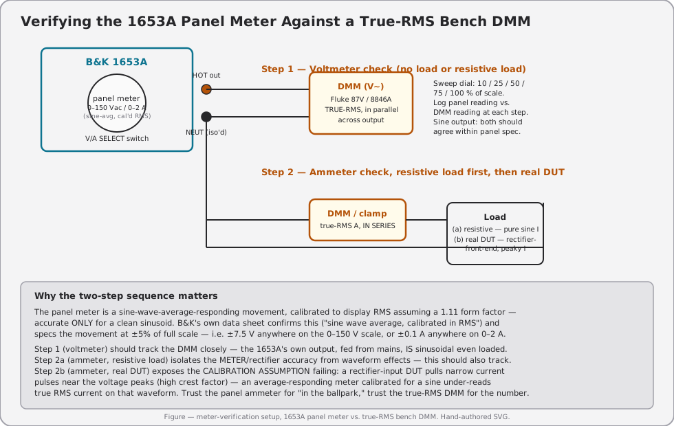
Per B&K Precision’s data sheet for the 1653A/1655A (2013 edition): voltage/current sensing is “sine wave average, calibrated in RMS”, and meter accuracy is ±5% of full scale on both functions. Two consequences fall directly out of that one line:
- “Average, calibrated in RMS” means the movement rectifies the waveform, averages it, and scales the result by the sine-wave form factor (1.11) to display an RMS-equivalent number. That’s accurate only if the waveform actually is a sine. The 1653A’s own output voltage is — it’s a scaled tap of the mains sine through a linear transformer chain, so the panel voltmeter should track a true-RMS DMM closely across the range.
- The panel ammeter reads the DUT’s current waveform, and DUT current is often not sinusoidal. A rectifier-input DUT (which is most tube-era B+ supplies and virtually all switch-mode gear) draws current in narrow pulses near the voltage peaks — high crest factor. An average-responding meter calibrated for a sine will under-read true-RMS current on a peaky waveform relative to what a true-RMS DMM or clamp meter reports. This is not a defect in the 1653A; it is what “sine-wave average, calibrated in RMS” means, applied to a non-sinusoidal load.
Note — This is exactly why you bring a true-RMS DMM (Fluke 87V, Fluke 8846A, or equivalent) to spot-check the panel ammeter under real load, rather than trusting the panel number as an absolute current figure — see the two-step verification procedure below and the figure that follows it.
5.6.2 Accuracy-Class Context
Analog panel-instrument accuracy is conventionally expressed as a class number equal to the maximum error as a percent of full scale — a framework the IEC/ANSI world both use, with common class steps of roughly 0.1, 0.2, 0.5, 1.0, 1.5, 2.5, and 5.0. Where the 1653A’s own ±5% of full scale lands in that ladder, and how it compares to the true-RMS DMM you’re checking it against:
Table 11 — Analog panel-instrument accuracy is conventionally expressed as a class number equal to the maximum error as a percent of full scale — a framework the IEC/ANSI world both use, with common class steps of roughly 0.1, 0.2, 0.5, 1.0, 1.5, 2.5, and 5.0. Where the 1653A's own ±5% of full scale lands in that ladder, and how it compares to the true-RMS DMM you're checking it against
| Accuracy class (≈ % of full scale) | Typical application | Where the 1653A’s panel meter sits |
|---|---|---|
| 0.1–0.2 | Laboratory/reference-grade standards | Far tighter than the 1653A’s panel meter |
| 0.5–1.0 | Precision bench instruments | Tighter than the 1653A’s panel meter |
| 1.5–2.5 | General-purpose panel/switchboard instruments | Tighter than the 1653A’s panel meter |
| 5.0 (approximate — the specific class-number naming for a commercial-grade indicating instrument is not independently confirmed against ANSI C39.1’s own text for this volume) | Commercial/utility-grade indicating instruments — “is the needle roughly where it should be,” not a metrology instrument | The 1653A’s published spec (±5% of full scale) lands here |
| Typical true-RMS bench DMM (Fluke 87V-class) | Basic AC voltage accuracy on the order of a few tenths of a percent of reading, plus a small count offset (specific figures vary by range and are published in the meter’s own datasheet) | Roughly one to two orders of magnitude tighter than the 1653A’s panel meter |
Note — The takeaway is not “the 1653A’s meter is bad” — it’s doing exactly what a commercial-grade panel indicator is for: giving the operator a fast, at-a-glance number to set and monitor voltage/current by. It was never intended as a precision reference, which is the entire reason this section exists — use it for control, use the DMM for the number that goes in a log.
5.6.3 Verification Procedure
- Voltmeter check — no load or a purely resistive load. Sweep the dial through 10%, 25%, 50%, 75%, and 100% of the 0–150 V scale. Log the panel reading against a true-RMS DMM reading in parallel at each point. Expect close agreement (within the panel’s ±5%-of-FS budget) at every step, since the source waveform is sinusoidal regardless of load.
- Ammeter check, resistive load — put a known resistive (non-reactive, sinusoidal-current) load on the output. Compare the panel ammeter against a true-RMS DMM or clamp meter in series. This isolates the meter movement/rectifier’s own accuracy from any waveform effect — expect agreement within spec here too.
- Ammeter check, real DUT — repeat with the actual rectifier-input or switch-mode DUT you intend to run. Expect the panel reading to diverge from the true-RMS DMM reading, and log the divergence. That gap is the crest-factor error described above, not a fault to “fix.”
- Log every run — panel reading, DMM reading, computed error, load type, date — in this instrument’s
DEVELOPMENT.md, and cross-reference the hub’s future Calibration/Metrology synthesis document (planned, not yet authored as of this writing) once that document exists.
5.6.4 Suggested Calibration / Verification Cycle
Table 12 — Suggested Calibration / Verification Cycle
| Check | Suggested interval | Method | Pass / fail criterion |
|---|---|---|---|
| Voltmeter vs. true-RMS DMM, no load | Every 6–12 months, or after any suspected meter damage | §5.6 Step 1 | Within ±5% of full scale (±7.5 V) at every checked point |
| Ammeter vs. true-RMS DMM, resistive load | Every 6–12 months | §5.6 Step 2 | Within ±5% of full scale (±0.1 A) at every checked point |
| Ammeter vs. true-RMS DMM, real DUT load | Whenever precision current matters for a specific test (brown-out margin runs, cap-reform leakage) | §5.6 Step 3 | Divergence expected and logged, not a pass/fail in the usual sense — record the gap for that DUT class |
| Fuse rating / condition (line + output) | Every session (visual), replace proactively if history unknown | Visual + continuity check | Correct rating (3A) for both fuses, intact |
5.7 Common Failure Modes of the 1653A Itself
Table 13 — Common Failure Modes of the 1653A Itself
| Symptom | Likely cause | Fix / service action |
|---|---|---|
| Ammeter reads zero with a confirmed load present | Open rectifier diode or open shunt in the ammeter’s sensing path | Verify with a DMM in series first (don’t assume the panel meter is right); if DMM shows current and panel doesn’t, the meter’s current-sense path has failed |
| Ammeter reads roughly half of the true-RMS DMM reading | One diode of the ammeter’s rectifier bridge has failed open — half-wave rectification instead of full-wave | Replace the failed bridge diode; re-verify per §5.6 afterward |
| Voltmeter reads full-scale-pegged or dead regardless of dial position | Open multiplier/shunt resistor in the voltmeter path, or the meter movement itself has failed | Isolate meter-select switch wiring first (cheap, common failure) before condemning the movement |
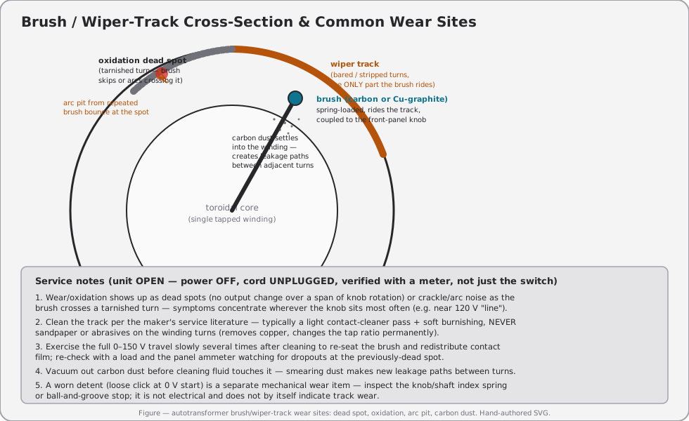
| Output doesn’t reach full 150 V, or output has a “dead spot” — no change over a span of knob rotation | Slip-ring / wiper-track oxidation at that rotational position — the brush is riding over a tarnished, non-conducting turn | Open the case (power OFF, cord unplugged, verified), clean the wiper track per §5.7 and the service figure below |
| Crackling / arcing sound as the knob turns, worse at one spot | Brush arcing across an oxidized or pitted turn — the tarnish is bad enough that contact is intermittent, not just resistive | Same as above; if pitting is deep, the track segment may need more than a cleaning pass — consult service literature for that specific unit’s brush/track assembly |
| Needle flutters or output current dips momentarily at certain knob positions, otherwise normal | Brush chatter — spring tension weak, or light oxidation not yet bad enough to be a hard dead spot | Clean per §5.7; if chatter persists after cleaning, inspect brush spring tension |
| Carbon dust visible inside the housing near the brush arm | Normal brush wear product, accumulating over the unit’s service life; becomes a problem once it bridges adjacent turns | Vacuum out before any cleaning fluid is applied (§5.7) — smearing dust creates new leakage paths rather than removing the existing ones |
| Detent at the 0 V position feels loose, or the knob doesn’t index the same way each time | Worn mechanical stop/index spring — unrelated to the electrical wiper-track condition | Mechanical service item; inspect the knob/shaft index hardware. Does not by itself indicate wiper-track wear |
| Fuse blows immediately at power-up with nothing plugged into the output | Internal short — likely in the iso-transformer, the fuse holder itself, or wiring ahead of the output receptacle | Do not just replace the fuse and try again — isolate the fault first, this is not a “the fuse was just old” situation |
⚠ Danger — Any brush/wiper-track service happens with the unit unplugged and verified dead — not just switched off. The 1653A carries both a mains-side primary and an isolated secondary inside the same enclosure; treat both as live until you’ve confirmed otherwise with a meter, per the one-hand-rule discipline in Vol 3.
5.8 Wiper-Track Cleaning — Step Sequence
- Unplug the unit. Verify dead with a meter across both the mains input and the output terminals — do not trust the switch position alone.
- Open the case per the service literature for this specific unit.
- Vacuum out loose carbon dust before applying any cleaning fluid (§ failure-mode table, “carbon dust” row).
- Apply a light, appropriate contact cleaner to the wiper track — never abrasives (sandpaper, emery cloth) on the winding turns themselves; abrasives remove copper and permanently change the tap ratio at that point on the winding.
- Gently burnish the track per the maker’s service guidance, following the direction of brush travel.
- Re-close the case, restore power, and slowly exercise the full 0–150 V travel several times to re-seat the brush and redistribute contact film across the freshly cleaned track.
- Re-check under load, watching the panel ammeter through the full sweep, for the dead spot or arcing that prompted the service in the first place. If it persists, the pitting is likely too deep for a cleaning pass alone — treat as a deeper mechanical service item.
5.9 Mod Opportunities
Table 14 — Mod Opportunities
| Mod | What it adds | Effort | Caution |
|---|---|---|---|
| Input EMI / line filter | Reduces conducted noise the 1653A’s own switching-free but still-inductive path can pass through onto the isolated output — useful when the DUT downstream is sensitive audio or RF gear | Low–moderate: an off-the-shelf inline AC line filter module wired in series with the mains input, inside or ahead of the enclosure | Adds another set of mains-carrying connections inside the case; enclosure grounding and isolation integrity must be preserved, not compromised, by the added wiring |
| Scope-monitor output tap | A dedicated pair of binding posts (or BNC via an appropriately isolated/attenuated interface) paralleling the output, meant for a differential probe | Moderate | Never use a single-ended, ground-referenced scope probe directly on the isolated output — the probe’s ground clip re-introduces exactly the earth-referenced path the isolation transformer exists to remove, and on a “hot chassis” DUT downstream this can be a shock or short hazard. See Vol 3’s isolation-and-grounding discussion before wiring this up. A true differential probe, or an isolated/battery scope, avoids the problem |
| External current-shunt output tap | A low-value shunt resistor added in series with the output hot lead, brought out to a shielded connector for a DAQ or scope | Moderate | Also solves the crest-factor problem from §5.6 directly — a shunt feeding a scope or a true-RMS-capable DAQ channel captures the actual current waveform, not just an average-responding meter’s sine-assumption number. Size the shunt low enough that its own voltage drop doesn’t meaningfully perturb the DUT |
| Brush/contact preventive refresh kit | Pre-stage a cleaning kit (appropriate contact cleaner, vacuum access, spare brush if the maker’s service parts are still available) rather than waiting for a failure | Low | Not a circuit mod — a maintenance-readiness mod. Cheapest insurance against the wiper-track failure modes in §5.6’s table |
⚠ Danger — The scope-monitor tap is the mod most likely to quietly defeat the entire reason this instrument exists. Isolation only protects you if nothing downstream re-bonds the floating side back to earth — a careless single-ended probe ground clip does exactly that. Read Vol 3’s isolation-breaks-the-ground-loop material before wiring any monitor tap, and see _shared/legal_ethics.md for the hub’s general bench-safety posture.
5.10 Session & Maintenance Log Template
A minimal log worth keeping in this instrument’s own DEVELOPMENT.md, distinct from any per-DUT project log:
Table 15 — A minimal log worth keeping in this instrument's own DEVELOPMENT.md, distinct from any per-DUT project log
| Date | Session type (routine / brown-out / cap-reform / cal-check) | Fuse check (line + output) | Panel-vs-DMM delta (if checked) | Notes |
|---|---|---|---|---|
Keeping this running, even sparsely, is what turns “the panel ammeter felt off once” into an actual trend worth acting on — a single anecdote is noise, three logged sessions showing the same drift is a service item.
5.11 Bridging to Vol 6
The tables in this volume that are stable, repeatable, and DUT-independent — the pre-session checklist (§5.1), the current-limiter method comparison (§5.5), and the calibration/verification cycle (§5.6) — are exactly the kind of material Vol 6 condenses onto the bench cheatsheet. Vol 6 doesn’t re-derive any of it; it’s a synthesis pass over this volume plus Vols 2–4, trimmed to what fits on cardstock.
Sources
- B&K Precision Corp., “AC Power Supplies — Models 1653A & 1655A” data sheet (v020713, © 2013), retrieved via rftesolutions.com mirror. Verified directly from the PDF: voltage adjustment range 0–150 Vac with 120 Vac input, 300 VA; output isolation leakage <0.1 mA (25°C, 50% RH); current range 2 A continuous (0–130 V) for the 1653A / 0–3 A continuous, 4 A intermittent (1655A); voltage/current sensing “sine wave average, calibrated in RMS”; meter scale 0–150 Vac / 0–2 A; metering for the 1653A is a single 2 in., overrange-protected, dual-function movement (the 1655A carries a separate 3-1/4 in. multi-function movement with additional current/leakage scales — do not attribute that spec to the 1653A); meter accuracy ±5% of full scale; power requirements 120 Vac ±10%, 60 Hz; dimensions 5.5″×6.5″×10.5″; weight 12 lbs.
- B&K Precision, 1653A/1655A instruction manual (bkpmedia.s3.amazonaws.com/downloads/manuals/en-us/1653A_manual.pdf). Read end to end for this revision of the volume: zero occurrences of GFCI / GFI / ground-fault / differential / interrupter anywhere in the manual. The 1653A’s actual front-panel controls are a POWER ON switch, a POWER ON pilot light, an alternate-action Function pushbutton (VOLTS out / AMPS in only), the single 2 in. meter, the AC VOLTS control, and one ISOLATED OUTPUT receptacle; its only overcurrent protection is a 3A line fuse plus an internal 3A output fuse. A resettable 3.15A circuit breaker, a power-line leakage-test probe, a 3-1/4 in. multi-function meter, and a soldering-iron temperature-control outlet are all explicitly 1655A-only features — asterisked and gated “Model 1655A” throughout the manual — and do not apply to the 1653A this hub covers.
- ANSI C84.1 voltage ranges for a 120 V nominal system: Range A ≈ ±5% (114–126 V); Range B ≈ +6%/−13% at the utilization end (~104–127 V) — corroborated across secondary sources (PG&E voltage tolerance boundary document, ANSI Blog, Electrical Engineering Portal); the current edition is ANSI C84.1-2020 (R2025), not independently pulled from the standard’s own text.
- Utility “brownout” typically described as a 10–25% deliberate voltage reduction — secondary sourcing (Wikipedia “Brownout (electricity),” multiple utility-industry explainer pages); no single authoritative numeric definition exists industry-wide, flagged as approximate.
- Dim-bulb-tester self-limiting behavior (cold-filament low resistance rising with temperature/current) is standard vacuum-tube-restoration bench practice; not tied to a single citable spec, presented as widely-documented technique.
- Reform-curve leakage-current rule-of-thumb figures in §5.4 are explicitly flagged as bench folklore, not a manufacturer or standards-body spec.
- Dim-bulb wattage / resistor-value worked examples in §5.4–5.5 are illustrative, not unit-specific engineering values — size them to the specific caps and DUT on your bench.