B&K 1653A Variac · Volume 6
B&K 1653A Variac — Vol 6: Cheatsheet (laminate)
One page, both sides, cardstock — every table you need at the bench with zero scrolling back to Vols 2–5.
6.1 How to Use This Sheet
Print, laminate, hang it on the cabinet next to the 1653A. Every row below is a synthesis of Vols 2–5 — the “detail” column tells you which volume to open if a row raises a question this sheet can’t answer. This sheet assumes you have already read Vol 1’s unknown-chassis decision tree and Vol 3’s safety theory at least once. It is a reference for the moment, not a substitute for that first read.
⚠ Danger — This sheet never replaces the one-hand rule, the pre-flight visual inspection, or the abort criteria. If a row and your gut disagree, your gut wins — kill the power and re-read Vol 3 §1 / Vol 4 before touching the chassis again.
Sibling test-equipment doc set for the same workflow: Heathkit IP-32 (regulated HV supply used after ramp-up), Heathkit SP-2717A (scope-side HV), Heathkit TT-1 (tube verification before re-installing a suspect tube), and the shared legal_ethics.md doc for acquisition/handling ethics that sit outside this instrument’s own safety scope.
6.2 1653A Quick-Spec Reference
Pull this table before you assume a number — don’t guess the dial range or fuse rating from memory. Full spec sheet and comparison against bare autotransformers (Staco 3PN1010B, Powerstat 116B): Vol 2.
Table 1 — 1653A Quick-Spec Reference
| Parameter | Value | Detail |
|---|---|---|
| Output voltage range | 0–150 Vac, continuously adjustable | Vol 2 (spec sheet) |
| Output current rating | 2 A continuous (0–130 V); tapers above 130 V within the 300 VA envelope — don’t invent an exact number, read Table 1 in the manual before pushing past 130 V | Vol 2 (spec sheet, derating table) |
| AC input | 120 Vac, 60 Hz, 300 VA | Vol 2 (spec sheet) |
| Isolation | Built-in series 1:1 isolation transformer, separate from the autotransformer winding | Vol 2 (block diagram), Vol 3 (why isolation matters) |
| Leakage current (mfr-published, 25°C/50% RH) | < 0.1 mA at the isolated output | Vol 2 — mfr-published figure, quoted directly |
| GFCI | None built in. The 1653A’s operator protection is isolation + fusing only — plug it into a GFCI-protected bench outlet if you want ground-fault protection | Vol 2, Vol 3 (Isolation vs. GFCI) |
| Metering | Single dual-purpose analog meter (0–150 V / 0–2 A), function selected by a front-panel VOLTS/AMPS switch — reads one at a time, not both simultaneously | Vol 2 (meter circuits), Vol 5 (calibration check) |
| Output protection | 3 A input line fuse + internal 3 A output fuse (fuse-protected, not a resettable breaker — the breaker is the 1655A). Never bypass or up-rate | Vol 2 |
| Meter accuracy (mfr-published, typical) | ±5% of full scale, calibrated at 120 Vac input, 25°C | Vol 2, Vol 5 (verification vs bench DMM) |
6.3 Front-Panel Walkthrough (quick)
Full routine-use narrative: Vol 5 §Routine Use.
Table 2 — Front-Panel Walkthrough (quick)
| Control / indicator | Set / read this way | Notes |
|---|---|---|
| Voltage control (autotransformer wiper) | Fully counter-clockwise / zero before power-on, every time | Never start a session with the dial already up |
| Line switch | On only after DUT is connected and voltage control is at 0 V | Sequence matters — see ramp table above |
| Function switch (VOLTS / AMPS) | Select AMPS to watch current through the dwell — this is the primary abort signal; flip to VOLTS only for the end-of-dwell voltage spot-check | Single dual-purpose meter, ±5% full-scale accuracy — it can’t show both at once, don’t chase the last volt or mA |
| Output receptacle / terminals | Confirm DUT is OFF before making/breaking connections | Standard bench discipline, not 1653A-specific |
6.4 Common Failure-Mode Quick Triage (the 1653A itself)
If the INSTRUMENT is misbehaving, not the DUT. Full failure-mode matrix with fixes: Vol 5 §Common Failure Modes.
Table 3 — Common Failure-Mode Quick Triage (the 1653A itself)
| Symptom | Likely cause | Quick action |
|---|---|---|
| Meter reads erratic or stuck (either VOLTS or AMPS position) | Shunt or rectifier-bridge failure in the meter circuit | Cross-check against a clamp meter/DMM before trusting readings |
| Dead spot or arcing as the dial sweeps a range | Brush wear / carbon dust, or slip-ring/wiper-track oxidation | Do not force through a dead spot — service the brush/track (Vol 5) |
| Detent/stop feels loose or dial doesn’t hold position | Worn mechanical detent | Cosmetic/usability issue, not a safety abort trigger by itself |
6.5 Brown-Out / Margin-Test Quick Recipe
For checking whether a DUT still runs correctly on a sagging line — not a power-up ramp. Full rationale and what a marginal result means: Vol 5 §Brown-Out Simulation.
Table 4 — Brown-Out / Margin-Test Quick Recipe
| Step | Action | Notes |
|---|---|---|
| 1 | Bring the DUT up to full nominal line voltage first, using the ramp table above | Never brown-out-test a chassis that hasn’t already been safely ramped once |
| 2 | Drop the 1653A output to 95 V, hold, observe DUT behavior | Simulates a moderate brown-out; watch for dropout, hum increase, instability |
| 3 | Drop further to 85 V only if 95 V was clean, hold, observe | This is a stress step, not routine use — abort criteria above still apply |
6.6 Slow-Ramp Profile by Chassis Class
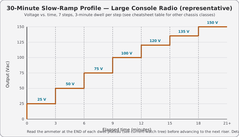
Dwell = minimum hold time at each step before advancing. Longer dwell on bigger iron because larger filter capacitor banks take longer to reform and larger power transformers take longer to reveal a shorted turn as rising case temperature. Full step derivation, dwell rationale, and the leakage-current curve behind it: Vol 4 (Power-Up Workflow).
The 1653A has one meter, function-switched — set the level with the meter on VOLTS, then flip the Function pushbutton to AMPS before the dwell ends so you’re reading current at the moment that matters. It can’t show both at once.
Table 5 — Slow-Ramp Profile by Chassis Class
| Chassis class | Steps (Vac, RMS at the 1653A dial) | Dwell per step | Watch for | Detail |
|---|---|---|---|---|
| Small AC/DC “5-tube” radio (transformerless, floating chassis) | 0 → 25 → 50 → 75 → 100 → 120 | 2 min | Filament glow at 25 V; case warmth of the filter cap by 75 V; any smell | Vol 4 (ramp table), Vol 3 (floating-chassis hazard) |
| Large console radio / large iron-power-transformer set | 0 → 25 → 50 → 75 → 100 → 120 → 135 → 150 | 3 min | Transformer hum changing pitch or growing louder; ammeter that won’t settle by minute 3 | Vol 4 (ramp table) |
| Console / table TV (tube type, isolated on the bench) | 0 → 20 → 40 → 60 → 80 → 100 → 120 | 3 min, 5 min at 120 V | HV flyback whine appearing; any hiss/corona; CRT anode area — do not approach until B+ is confirmed present and bled | Vol 3 (X-ray/HV), Vol 4 (ramp table) |
| Audio power amplifier (tube, output-transformer coupled) | 0 → 25 → 50 → 75 → 100 → 125 → 150 | 3 min | Output-tube plates glowing dull red (bias fault) before B+ is even near nominal; DC offset at the speaker terminals if measured | Vol 4 (ramp table), Vol 5 (routine-use walkthrough) |
| Transmitter / RF power amplifier (tube PA, multi-hundred-volt B+) | 0 → 20 → 40 → 60 → 80 → 100 → 120 → 140 → 150 | 5 min, hold 10 min at final step | Plate current creeping without drive applied; any corona/arcing at high-voltage tank components; smell of hot wax or varnish | Vol 4 (ramp table), Vol 3 (HV/X-ray callout) |
Note — These are starting points, not guarantees. A chassis with known history (you recapped it last month) can skip steps; a chassis with unknown history (attic find, estate-sale box) never skips steps — see Vol 1’s unknown-chassis decision tree for the always-ramp / bypass-acceptable / never-touch call before you even reach for this table.
6.7 Glossary Quick Reference
Fast lookups so this sheet stands alone at the bench. Full derivation of each term: Vol 1 (terms/decision tree) and Vol 2 (circuit theory).
Table 6 — Glossary Quick Reference
| Term | Quick definition | Detail |
|---|---|---|
| ”Variac” | Originally a General Radio trademark for a variable autotransformer; now genericized (small-v “variac”) the way “Kleenex” or “Thermos” is | Vol 1 |
| Variable autotransformer | A single tapped winding with a moving brush/wiper — adjusts voltage, but by itself gives NO galvanic isolation from the mains | Vol 1, Vol 2 |
| Isolation transformer | A separate winding pair (here, 1:1) that breaks the direct electrical path to earth ground — the 1653A stacks this ON TOP of its autotransformer | Vol 2, Vol 3 |
| GFCI (Class A) | Differential current sensor that trips around 4–6 mA (nominal 5 mA) of earth-fault current, in roughly 25 ms — general term; the 1653A itself has NO built-in GFCI, see the matrix below | Vol 2, Vol 3 |
| Floating chassis | A chassis whose “ground” reference isn’t earth ground — common in transformerless AC/DC radios and hot-chassis TVs; can sit at up to full line voltage relative to true earth | Vol 3 |
| Cap reforming | The self-healing rebuild of an aluminum-electrolytic capacitor’s internal oxide dielectric under slow, controlled voltage after long storage | Vol 4, Vol 5 |
| Dim-bulb tester | A series incandescent lamp used as a crude self-limiting current limiter — complementary to, not a replacement for, the 1653A’s isolation + metering | Vol 4, Vol 5 |
| One-hand rule | Keep one hand in a pocket or behind your back while probing live circuits, so a shock path can’t cross the heart chest-to-chest/hand-to-hand | Vol 3 |
6.8 Isolation vs. GFCI — General Safety Education (the 1653A has isolation, NOT a built-in GFCI)
These solve DIFFERENT problems. The 1653A itself provides isolation + fusing only — it has no built-in GFCI. If you want ground-fault protection on this bench, plug the 1653A into a GFCI-protected outlet/receptacle; that GFCI lives upstream of the 1653A, not inside it. Full reasoning and the “isolation can defeat a downstream GFCI” caveat: Vol 3 §Isolation vs. GFCI.
Table 7 — Isolation vs. GFCI — General Safety Education (the 1653A has isolation, NOT a built-in GFCI)
| Question | Isolation transformer | GFCI |
|---|---|---|
| What it does | Removes the earth-referenced return path entirely | Senses an earth-fault current and trips the circuit |
| Present on the 1653A? | Yes — built-in series 1:1 winding, downstream of the autotransformer | No — not built in; supply one externally via a GFCI-protected outlet if you want this protection |
| Does it make a hot chassis “safe to touch”? | No — the chassis can still be at full potential relative to another point in the circuit | No — it only protects the earth-fault path it can see |
| Can it be defeated by the other? | A floating isolated secondary removes the earth path a GFCI needs to sense — so an externally supplied, GFCI-protected outlet upstream of the 1653A cannot see a fault downstream of the isolation transformer | N/A — depends entirely on where you place it relative to the isolation stage |
| What it’s for here | Lets a grounded scope probe touch a hot chassis without completing a mains fault loop | Would catch a genuine mains-side ground fault (frayed cord, internal short to case) — but only if you supply it yourself, upstream |
Note — The 1655A sibling model adds a leakage-current MEASUREMENT function (a DUT test per UL/OSHA norms) — that’s a measurement tool for characterizing a device under test, not operator GFCI protection, and the 1653A doesn’t have that function either.
6.9 Calibration / Verification Quick Cycle (the 1653A’s own meters)
Full setup diagram and suggested interval: Vol 5 §Calibration/Verification.
Table 8 — Calibration / Verification Quick Cycle (the 1653A's own meters)
| Check | Reference instrument | Frequency | Notes |
|---|---|---|---|
| Voltmeter accuracy (function switch in VOLTS) | True-RMS bench DMM (e.g., Fluke 87V/8846A class) | Annually, or after any suspected mishandling | True-RMS matters — a non-RMS meter will disagree on non-sinusoidal loads |
| Ammeter accuracy (function switch in AMPS) | Clamp meter or DMM in series, at a known resistive load | Annually | Cross-check at both a low and a near-full-scale current point |
6.10 Mod Options Quick Reference (optional, not required for safe operation)
Full build notes and rationale: Vol 5 §Mod Opportunities.
Table 9 — Mod Options Quick Reference (optional, not required for safe operation)
| Mod | What it buys | Caution |
|---|---|---|
| Input EMI/line filter | Cleaner mains feed to sensitive DUTs, reduced noise coupling | Add ahead of the existing fuse chain, don’t disturb its wiring |
| Scope-monitor output tap | A safe, isolated point to watch the output waveform without probing the DUT directly | Must stay downstream of the isolation transformer to keep the isolation benefit |
| External current-shunt output for datalogging | Continuous current logging during long ramps/reforms | Verify it doesn’t change the ammeter’s own accuracy or trip behavior |
6.11 Current-Watch Decision Tree
Read the ammeter at the END of every dwell period, not mid-climb — Function switch on AMPS to do it, since the 1653A’s single meter can’t show volts and amps together. Full runaway-pattern triage matrix with root causes: Vol 4 §Current-Watch.
                         ┌─────────────────────────────┐
                         │  READ AMMETER AT END OF DWELL │
                         └───────────────┬───────────────┘
                                         │
                 ┌───────────────────────┼───────────────────────┐
                 │                       │                       │
        Brief inrush spike,      Current climbs but      Current SPIKES high
        then settles low         is still SLOWLY          the instant you
        and stays flat?          falling at end of         raise voltage,
                 │               dwell (not flat yet)?     even at a LOW step
                 │YES                    │YES              (<40 V)?
                 ▼                       ▼                       │YES
           ┌───────────┐        ┌────────────────┐               ▼
           │  NORMAL    │        │ CAP REFORMING   │      ┌───────────────┐
           │  advance   │        │ NORMALLY —      │      │ DEAD SHORT or  │
           │  to next   │        │ hold this step   │      │ SHORTED XFMR   │
           │  step      │        │ up to 2× dwell.  │      │ ── ABORT NOW   │
           └───────────┘        │ Still climbing    │      │ (see below)    │
                                 │ or not flat at    │      └───────────────┘
                                 │ 2× dwell?         │
                                 │        │YES        │
                                 │        ▼           │
                                 │  ┌────────────┐    │
                                 │  │ CAP LEAKY /  │    │
                                 │  │ NOT REFORMING│    │
                                 │  │ ── ABORT,    │    │
                                 │  │ do NOT push   │    │
                                 │  │ further, log  │    │
                                 │  │ and go to      │    │
                                 │  │ Vol 5 lab      │    │
                                 │  │ reform bench   │    │
                                 │  └────────────┘    │
                                 └────────────────┘
⚠ Danger — A current spike at a low voltage step is the one pattern that means “something is already broken,” not “something is healing.” Do not raise voltage further to “see what happens.”
6.12 Body-Current Physiology Quick Reference (why the one-hand rule exists)
Order-of-magnitude figures commonly cited from IEC 60479-1 body-current research — durations and exact mA figures vary by path, frequency, and individual; treat as approximate awareness levels, not a safety margin to calculate against. Full physiology discussion and the heart-crossing-path rationale for the one-hand rule: Vol 3 §One-Hand Rule.
Table 10 — Body-Current Physiology Quick Reference (why the one-hand rule exists)
| Approx. AC current (60 Hz, hand-to-hand) | Typical physiological effect |
|---|---|
| ~0.5–1 mA | Threshold of perception (tingle) |
| ~5–10 mA | ”Let-go” threshold region — muscle contraction can make it hard to release the conductor |
| ~20–40 mA | Risk zone for breathing difficulty / involuntary contraction over sustained contact |
| ~50–100+ mA (hand-to-hand, across the chest, ~1 s+) | Ventricular-fibrillation risk zone — commonly cited as the danger threshold for a heart-crossing path |
Note — These numbers are exactly why a hand-to-hand path (one hand on the chassis, one hand on a grounded bench fixture) is the path to avoid — it crosses the heart. The one-hand rule isn’t superstition; it’s routing the current path away from the heart if a mistake happens anyway.
6.13 Scope-Probe / Meter Voltage-Rating Quick Reference
Full probe-rating reference table and CAT ratings: Vol 3 §Probe Ratings.
Table 11 — Scope-Probe / Meter Voltage-Rating Quick Reference
| You’re probing… | Minimum probe/meter rating to use | Why |
|---|---|---|
| Low-voltage B+ rails, filament/heater circuits | Standard 300 V-class probe is typically adequate | Confirm against the probe’s own printed rating, not assumption |
| Screen/plate voltages on small-signal tube stages | 600 V-class probe recommended | Margin above nominal, not just “it probably won’t hit that” |
| Plate B+ on audio/RF power stages, CRT second-anode-adjacent nodes | High-voltage-rated probe (kV-class, purpose-built) | A 300 V probe on a multi-kV node is a fire/flashover risk, not a “slightly out of spec” risk |
| Any CRT anode lead directly | Do not probe casually at all — treat as a dedicated HV-probe, trained-procedure task | See Vol 3’s X-ray/HV callout — this is also an X-ray-emission concern on some high-anode-kV tubes, not just a shock concern |
⚠ Danger — Matching probe rating to the node’s WORST-CASE voltage, not its expected nominal, is the rule — a marginal supply or a fault condition can push a node well past its “normal” number.
6.14 Voltage Spot-Check Points by Chassis Class
Take these AFTER the ramp completes, meter still through the 1653A’s isolated output, one hand in your pocket. Point-by-point rationale and expected normal ranges for specific circuits: Vol 4 (post-ramp spot-checks), Vol 2 (circuit theory for what each node is).
Table 12 — Voltage Spot-Check Points by Chassis Class
| Chassis class | Primary spot-check points | Typical healthy indicator | Detail |
|---|---|---|---|
| Small AC/DC radio | B+ at first filter cap; across the pilot/dial lamp if fitted | B+ present, steady (not drifting); lamp at normal brightness by full line | Vol 4 §Post-Ramp |
| Large console radio | B+ at filter choke input and output; screen-grid voltage at output tube | Choke-input B+ higher than choke-output B+ by the choke’s IR drop; screen voltage stable | Vol 4 §Post-Ramp, Vol 2 (circuit theory) |
| Console/table TV | Low-voltage B+ rail; screen/focus voltages if externally accessible; do not probe the flyback/anode lead itself | Rails at nameplate/schematic nominal; no corona sound near the flyback | Vol 3 (X-ray/HV callout), Vol 4 §Post-Ramp |
| Audio power amp | B+ at output-tube plates; bias voltage at each output-tube grid; DC offset at speaker output | Plate voltages matched between paired output tubes; bias within the tube’s rated range | Vol 4 §Post-Ramp, Vol 5 (routine use) |
| Transmitter/RF PA | Plate B+ with no drive applied; screen B+; grid bias | Plate current near zero with no drive; bias present before B+ is ever applied | Vol 3 (HV/X-ray), Vol 4 §Post-Ramp |
6.15 Hazardous-Materials Quick-Reference
Condensed from Vol 3’s full HAZMAT catalog — identification cues and handling only. Full year ranges, citation basis, and detailed handling procedure: Vol 3 (Hazardous-Materials Catalog).
Table 13 — Hazardous-Materials Quick-Reference
| Material | Approx. years found | Where on a chassis | Handling |
|---|---|---|---|
| PCB-bearing oil | Pre-1979 (TSCA ban) | Oil-filled paper capacitors, some power-transformer potting | Do not open/drain; treat leaking units as hazardous waste, not trash |
| Asbestos | Pre-1980s, tapering after | Wirewound-resistor cores, flash/spark insulation, some heater sleeving | Do not sand, cut, or brush; if friable, bag and stop work |
| Selenium rectifiers | ~1940s–1970s (largely displaced by silicon by late 1960s) | Stacked-plate rectifiers, often finned/painted gray-green | Overheated units release SeO2/H2Se fumes — ventilate immediately, do not inhale the “rotten” smell |
| Mercury (switches/relays) | Through ~1990s in some industrial/telecom gear | Tilt switches, mercury-wetted relays, some older thermostats on chassis | Do not crush; handle a broken bulb as a mercury spill, not sweepings |
| Beryllium oxide (BeO) | Ongoing where used — mainly RF power-transistor and diode heat-sink spreaders | White/gray ceramic insulator wafers under RF power devices | Never sand, grind, or crack — dust is the hazard, not the intact part; discard intact if in doubt |
| Wax-paper / “black beauty” caps | 1940s–1960s | Coupling/bypass caps throughout signal and bias circuits | Leaking wax is a mess, not typically a toxic hazard — but treat as failed, replace, don’t reuse |
| Transformer tar/pitch potting compound | Widespread through mid-20th century | Power and output transformer potting, some multi-section can capacitors | Overheated tar smells sharp/acrid — a strong tar smell during ramp-up is itself an abort trigger, not just a hazmat note |
| Rubber/cotton-braid wire insulation | Pre-1960s-ish, tapering after | Chassis wiring, especially point-to-point runs on early sets | Brittle insulation cracks and can expose bare conductor — inspect before energizing, don’t just visually skim past it |
⚠ Danger — Selenium-rectifier and BeO hazards are both release-on-damage, not present-in-normal- use. Normal slow-ramp operation should never release either — it’s overheating (selenium) or mechanical damage (BeO) that turns them dangerous. That’s one more reason the ramp protocol above matters.
6.16 Emergency-Abort Recipe
Table 14 — Emergency-Abort Recipe
| Step | Action | Notes |
|---|---|---|
| 1 | Turn the 1653A’s output/voltage control to 0 V — do not just flip the DUT’s own switch | Killing at the source is faster than fighting a possibly-fused or possibly-arcing DUT switch |
| 2 | Unplug the 1653A’s line cord from the wall | Removes the mains feed entirely — don’t assume the fuse has already opened |
| 3 | Let the chassis sit — do not touch it, probe it, or open it up — until filter capacitors have had time to bleed down | Large filter caps can hold lethal charge for minutes after power is removed; see Vol 3 (one-hand rule / physiology) for why “it’s unplugged” is not “it’s safe” |
Abort triggers (any ONE is sufficient): current excursion past roughly 2× the expected value for that step · any visible smoke · any audible arcing, sizzling, or corona hiss · any hot-component, ozone, or burning-insulation smell. Full abort-criteria matrix with per-symptom likely cause: Vol 4 §Abort Criteria.
⚠ Danger — Never troubleshoot during an abort. Kill it, walk away, THEN diagnose with the unit fully de-energized and bled down.
6.17 Full-Session Checklist (top to bottom)
The condensed run order — every other table on this sheet slots into one of these phases. Full narrative for each phase: Vol 4 (power-up workflow) and Vol 5 (routine use).
Table 15 — Full-Session Checklist (top to bottom)
| Phase | Do this | Table/section on this sheet |
|---|---|---|
| 1. Pre-flight | Visual inspection of line cord, plug, strain relief; confirm the 1653A’s own line cord ground pin is intact and the bench outlet is properly earthed; confirm the 3 A line fuse and internal 3 A output fuse are both intact (no history of unexplained blows); flip the Function switch to VOLTS and AMPS in turn and confirm the meter needle responds/rests correctly in both positions; voltage control fully counter-clockwise (0 V) before power-on | Front-Panel Walkthrough |
| 2. Chassis-out inspection | Look for bulging/vented caps, leaking wax-paper caps, charred resistors, cracked tube envelopes, crumbling rubber/cotton wiring, transformer tar smell | Hazardous-Materials Quick-Reference (identify what you’re seeing) |
| 3. Connect DUT | DUT switch OFF, connect to isolated output, confirm chassis class | Front-Panel Walkthrough |
| 4. Ramp | Step voltage per chassis class, dwell, read ammeter at end of each dwell | Slow-Ramp Profile by Chassis Class |
| 5. Watch current | Classify what the ammeter is doing at each step | Current-Watch Decision Tree |
| 6. Abort if triggered | Any trigger condition → kill immediately, do not diagnose live | Emergency-Abort Recipe |
| 7. Post-ramp spot-check | Verify key voltages with the isolated meter, one hand in pocket | Voltage Spot-Check Points by Chassis Class |
| 8. Shutdown | Voltage control back to 0 V before switching off; let bleed down before opening the chassis further | Emergency-Abort Recipe (same bleed-down caution applies to routine shutdown) |
6.18 Ramp-Profile Chart
6.19 Depth Index — Where Each Table Came From
Table 16 — Depth Index — Where Each Table Came From
| This sheet’s section | Full treatment |
|---|---|
| 1653A quick-spec reference | Vol 2 — full spec sheet + comparison vs. Staco/Powerstat |
| Front-panel walkthrough | Vol 5 §Routine Use |
| Common failure-mode quick triage | Vol 5 §Common Failure Modes |
| Brown-out quick recipe | Vol 5 §Brown-Out Simulation |
| Glossary | Vol 1 (terms), Vol 2 (circuit theory) |
| Isolation vs. GFCI general safety education | Vol 3 §Isolation vs. GFCI |
| Calibration/verification cycle | Vol 5 §Calibration/Verification |
| Mod options | Vol 5 §Mod Opportunities |
| Body-current physiology | Vol 3 §One-Hand Rule |
| Probe voltage-rating reference | Vol 3 §Probe Ratings |
| Slow-ramp profile | Vol 4 (Power-Up Workflow) — ramp-profile table + cap-reform theory |
| Current-watch tree | Vol 4 §Current-Watch — runaway-pattern triage matrix |
| Voltage spot-checks | Vol 4 §Post-Ramp Spot-Checks; circuit context in Vol 2 |
| Hazmat quick-ref | Vol 3 (Bench Safety) — full HAZMAT catalog with sourcing |
| Full-session checklist | Synthesizes Vol 4 + Vol 5 into one run order |
| Abort recipe | Vol 4 §Abort Criteria; physiology/one-hand rule in Vol 3 |
| Unknown-chassis routing (not reproduced here) | Vol 1 — always-ramp / bypass-acceptable / never-touch decision tree |
Sources
- B&K Precision 1653A/1655A data sheet (v053018, 2018; rftesolutions.com mirror) and Transcat-hosted 1653A/1655A instruction manual: confirmed 0–150 Vac output range, 0–2 A output current, built-in isolation transformer, a single dual-purpose analog meter selected by a front-panel VOLTS/AMPS function switch, a 3 A input line fuse plus a separate internal 3 A output fuse, leakage less than 0.1 mA (25°C/50% RH) at the isolated output, and a published meter accuracy of ±5% of full scale (typical, 25°C, calibrated at 120 Vac input) — used to set this sheet’s voltage/current framing. Both documents contain ZERO mention of GFCI, ground-fault, or interrupter, and the manual’s front-panel control list has no TEST/RESET buttons — the 1653A’s operator protection is isolation + fusing only, no built-in GFCI. (The 1655A sibling adds a leakage-current MEASUREMENT function — a DUT test per UL/OSHA norms — which is a measurement tool, not operator GFCI protection, and the 1653A doesn’t have that function either.) NOT used to invent any number B&K doesn’t publish.
- UL 943 Class A GFCI trip-threshold research (Mike Holt forums summary, code-authorities.ul.com PDF, csemag.com “UL’s new GFCI classes”): confirmed Class A trips in the 4–6 mA range (nominal 5 mA), with a published response-time curve (~25 ms at 5 mA, tightening to ~20 ms above 300 mA). This is general GFCI-class background for the Isolation-vs-GFCI education table only — it describes an EXTERNAL, user-supplied GFCI-protected outlet, not any component inside the 1653A, which has none.
- All ramp-step counts, dwell times, and abort thresholds (“~2×” current excursion) are this program’s synthesized, conservative bench practice — not manufacturer-published numbers for any specific chassis. They are deliberately framed as starting points in the sheet’s own callouts, not hard specs.
- Body-current physiology figures (perception ~0.5–1 mA, let-go region ~5–10 mA, ventricular-fibrillation risk zone commonly cited around 50–100+ mA for a sustained hand-to-hand path) were checked against general summaries of IEC 60479-1 body-current research. These figures vary meaningfully by exposure duration, current path, and individual physiology in the underlying standard’s own tables — this sheet intentionally presents them as rounded order-of-magnitude awareness bands, not a calculated safety margin; Vol 3 gives the fuller treatment.
- The isolation-can-defeat-a-downstream-GFCI relationship is standard bench-safety reasoning for isolation transformers paired with GFCI protection generally. It applies here only in the sense that IF a user supplies an external, GFCI-protected outlet upstream of the 1653A, that GFCI cannot see a fault occurring downstream of the 1653A’s own isolation transformer — this is general reasoning about isolation transformers, not a manufacturer statement about any component inside the 1653A itself.
- Historical hazardous-material year ranges (selenium rectifiers largely displaced by silicon through the 1960s–70s, PCB TSCA ban 1979, asbestos tapering through the 1980s, mercury switches persisting into the 1990s in some equipment) are broad, commonly cited industry ranges rather than precise dated cutoffs — treat any specific unit’s actual construction date as the deciding factor, not the year range alone.
This volume is a pure synthesis of Vols 2–5’s own sourced material; it introduces no new primary claims beyond the two web-verified items above. Any correction made to a fact in Vols 2–5 during review should be mirrored here, since this sheet restates those numbers in compressed form.