B&K Dynamic 375 VTVM · Volume 2
B&K Dynamatic 375 — Vol 2: How a VTVM Works — The Balanced Bridge, Rectifier & Ohms Circuit
A grid that draws no current, a bridge that reads imbalance instead of raw current, and a 1.5 V cell that doubles as its own battery-health check.
Vol 1 established what the 375 is and why an 11 MΩ needle still earns bench space. This volume is the schematic-grade follow-through: how that 11 MΩ figure is actually built out of a resistor at the probe tip and a divider inside the case, how a single 12AU7 dual-triode turns a few millivolts of grid signal into a meter deflection without ever letting the meter movement itself touch the circuit under test, how the 6AL5 turns AC into something the same DC circuit can read, and how a $0.50 flashlight battery becomes an ohmmeter. None of this is unique to the 375 — it’s the shared VTVM circuit family that also underpins the Simpson 311-2 on the other side of Jeff’s bench — but the specific component values and control names below are the 375’s own, read off its schematic and cross-checked against a service-forum repair thread. Confidence tags are used throughout this convention: [CONFIRMED] = primary/multiple sources, [LIKELY] = one decent source, [UNCERTAIN] = thin or conflicting, [NOT FOUND] = could not verify. Where the underlying research could not pin a number down, this volume says so rather than inventing one.
2.1 Why a Grid Draws (Almost) No Current
Every voltmeter design question starts from the same fact: to deflect a needle, you have to draw some current from somewhere. The entire VTVM idea is a way of drawing that current from a source the meter provides for itself — a vacuum tube’s B+ supply — rather than from the circuit under test. Understanding why that works starts with what a control grid does and does not do.
2.1.1 The grid as a fence, not a pipe
Inside a triode, the cathode boils off a cloud of electrons (thermionic emission), and the plate, held positive relative to the cathode, pulls that cloud across the vacuum as plate current. The control grid sits between them — a fine wire mesh, not a solid electrode — and is normally biased negative relative to the cathode. A negative grid repels electrons; it doesn’t attract or collect them. The grid’s job is to modulate how many electrons get past it on their way from cathode to plate, and it does that job electrostatically, by shaping the field the electrons fly through, without needing to physically intercept any of them.
The practical result: in normal operation, essentially no electrons land on the grid itself. What current does flow into a grid circuit — call it grid current, typically well under a nanoamp in a healthy tube biased solidly negative — comes from second-order effects: a trace of residual gas in the envelope getting ionized, thermal or photoelectric emission from the grid structure itself, tiny leakage paths through the socket and glass. None of that is the electron beam being “read out” the way a meter movement’s coil reads out current. A grid, electrically, behaves like a capacitor plate with a very large parallel leakage resistance — commonly hundreds of megohms to low gigohms for a good tube — not like a wire.
Note — this is the single fact the entire VTVM concept is built on. A moving-coil meter movement must pass real current through its coil to deflect the needle — that’s what a coil does. A tube’s control grid does not have to pass current to do its job. Put the grid, not the coil, across the node you’re measuring, and you’ve decoupled “how much current do I have to draw from the circuit” from “how sensitive is my display.”
2.1.2 A moving-coil VOM can’t escape this trade-off — a tube grid already has
A conventional analog VOM (a Simpson 260, for instance) has no way around the coil-current problem. Its input resistance on any DC range is fixed by its sensitivity rating (Ω/V) times the full-scale voltage of that range — a 20 kΩ/V meter on its 2.5 V range is a 50 kΩ load, full stop, because that’s how much resistance is needed to limit the coil to its rated full-scale current at 2.5 V. Make the coil more sensitive (lower full-scale current) and the input resistance goes up, but so does the coil’s fragility and its susceptibility to being overloaded or damaged by even a modest overvoltage. There’s a hard physical ceiling on how far that trade can be pushed with a moving coil alone.
A tube sidesteps the trade-off entirely. The grid draws (almost) no current at any signal level within its rated bias range, so the input resistance the circuit under test sees is set not by the meter movement’s sensitivity but by whatever resistor network the designer chooses to put between the test point and the grid. That network can be made as large as practical component tolerances, leakage, and cable capacitance allow — and the tube’s own gain then does the work of turning that tiny grid signal back into enough plate current to swing a completely ordinary 100 µA meter movement. The grid decouples input impedance from meter sensitivity; that decoupling is the whole trick.
2.1.3 So where does “11 megohms” actually come from?
If the tube’s native grid impedance is already in the hundreds-of-megohms range, why does the 375 land on a comparatively modest 11 MΩ rather than something far higher? Because the tube was never the limiting factor — the practical limiting factors are all on the resistor-network side of the grid, not the tube side:
- Divider accuracy. A useful voltmeter needs an accurately known attenuation ratio on every range. Precision resistors in the hundreds-of-megohm range were (and still are) expensive, drift more with humidity and age than lower values, and are harder to trust to a stated tolerance. B&K’s ad specifies ±1% multiplier resistors [CONFIRMED] — a tolerance that’s realistic at megohm values but gets progressively harder to hold as the values climb into the hundreds of megohms.
- Leakage and noise floor. Once the resistor network’s own value starts approaching the tube’s native grid leakage resistance, the network stops being the dominant term and stray leakage (dirty sockets, humid PC-board surfaces, the probe cable itself) starts contributing measurable error. Ten to twenty megohms sits comfortably below that crossover for 1960s-era construction practice.
- Enough headroom against real tube-circuit source impedances. Vol 1 §1 makes the loading-error case in full; the short version is that most tube-circuit source impedances worth measuring — grid-bias networks, AVC lines, screen droppers — run from the tens of kilohms up into the low megohms. An input impedance an order of magnitude or more above that ceiling already gives a comfortably small loading error without having to chase impractically large resistor values for a marginal further improvement.
11 MΩ, in other words, isn’t a limit imposed by the tube — it’s a design point chosen because it’s comfortably higher than the source impedances that matter, while staying inside the range where ±1% resistors are practical and leakage stays a non-issue. It happens to split cleanly into a 1 MΩ resistor that lives in the probe tip and a 10 MΩ divider that lives in the chassis, which is §2’s subject.
2.2 The Probe: A Series Isolation Resistor and a 1 MΩ + 10 MΩ Divider
2.2.1 One resistor, two jobs
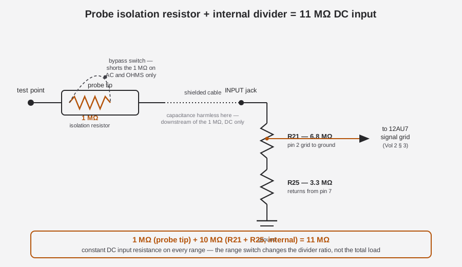
The 375 ships with a single DC-AC-Ohms probe [CONFIRMED — 1961 ad]. Inside its tip, per the standard design convention for VTVM probes of this era, sits a ~1 MΩ series isolation resistor [LIKELY — by analogy to sibling B&K probes; the design pattern is well documented across the era’s VTVM probe family]. That resistor does two jobs at once:
- It isolates the cable from the test point. A probe cable a few feet long carries meaningful shunt capacitance — tens of picofarads is typical for shielded test lead. Put a resistor at the tip, ahead of that cable, and the source only ever sees the tip resistor (plus a negligible sliver of tip capacitance) in parallel with the node — the cable’s capacitance, and everything downstream of the resistor all the way to the 12AU7 grid, is buffered from the source by that 1 MΩ. Put the same resistor at the chassis end instead, and the cable capacitance sits directly across the test point, un-isolated, which would matter for AC/RF work and for fast transients even though it’s mostly invisible on a steady-state DC reading. This is the same reasoning that later drove every 10:1 oscilloscope probe to put its compensation resistor at the tip rather than the BNC end.
- It limits fault current into the grid circuit. If the probe lands on a node well outside the selected range — a stiff B+ rail on the 1.5 V range, say — the 1 MΩ resistor caps how much current can flow into the divider and grid circuit behind it, protecting the precision divider resistors and the 12AU7’s grid from a hard overload.
2.2.2 The internal 10 MΩ divider
Behind the input jack, the range-switch attenuator string sets up a known fraction of the input voltage at the 12AU7’s signal grid. Two of those resistors, verified from a service-forum repair thread working directly from the schematic, anchor the top of that string:
Table 1 — directly from the schematic, anchor the top of that string
| Designator | Value | Location |
|---|---|---|
| R21 | 6.8 MΩ | 12AU7 pin 2 (signal grid) to ground |
| R25 | 3.3 MΩ | Returns from pin 7, in series with R21’s leg of the divider |
| Sum (R21 + R25) | ~10 MΩ | The internal half of the input divider |
[CONFIRMED — antiqueradios.com “B&K Dynamatic 375 VTVM woes” service thread, working from the schematic]
Add the probe’s 1 MΩ isolation resistor in series ahead of that ~10 MΩ, and the total is the ad’s headline figure:
1 MΩ (probe tip) + 10 MΩ (R21 + R25, internal) = 11 MΩ, constant on every DC range [CONFIRMED — ad: “Input Resistance: 11 megohms on all DC ranges”]
The word constant matters. The RANGE switch changes which tap on the precision multiplier/attenuator string feeds the grid — that’s how the same 100 µA bridge reads 1.5 V full scale on one range and 1500 V full scale on another — but it does not change the total resistance the test point sees looking into the probe. Every range presents the same 11 MΩ, because the range switch sits downstream of the point where the source current actually flows in; it reconfigures the divider ratio, not the total load. That’s the property Vol 1 leaned on to say the 375’s input impedance is “one number, constant, regardless of what range you’ve dialed in,” and this is the resistor-level reason why.
2.2.3 Why AC and Ohms switch the 1 MΩ resistor out
Per the standard B&K/era probe design, the tip’s 1 MΩ series resistor is switched out (shorted) for AC and Ohms [CONFIRMED that a single probe is supplied; the 1 MΩ-switch design itself is LIKELY, by analogy to sibling B&K probes rather than a confirmed 375-specific schematic trace]. The reasoning differs by function:
- On Ohms, it’s close to mandatory. The ohms circuit works by passing a known current from the internal battery through the unknown resistance and reading the resulting voltage (§5 below). Leave a fixed 1 MΩ resistor in series with that loop and it swamps every reading on the low ohms ranges — a 1 MΩ series resistor added in front of a 500 Ω or 5 kΩ range would make the low end of the scale unreadable, since the added resistance would dwarf the unknown resistance being measured. The probe resistor has to come out of the ohms current path entirely for the low ranges to mean anything.
- On AC, the reasoning is a bandwidth and calibration-independence argument. A fixed resistor at the tip forms an RC low-pass filter with the cable’s own shunt capacitance and whatever input capacitance the 6AL5 rectifier stage presents; shorting it out for AC removes that rolloff from the AC signal path and keeps the AC calibration independent of any resistor-value tolerance in the tip. [LIKELY — reasoned from the general design pattern; not a confirmed 375-specific schematic annotation]
Note — because the same physical probe serves DC, AC, and Ohms, and each function needs a different effective source resistance ahead of the grid, the function switch (not just the range switch) is doing real electrical work here — it’s not simply selecting a scale to read, it’s reconfiguring which resistors are actually in the signal path. Vol 3’s control tour covers the FUNCTION SELECTOR’s full set of positions (OFF · AC P-P · AC RMS · DC+ · DC− · OHMS · DC MA).
2.2.4 A worked example: how one 11 MΩ input serves seven ranges
It’s worth being explicit about how a single fixed 11 MΩ input can present seven different full-scale readings (1.5 V through 1500 V) without the input resistance itself ever changing. The RANGE switch doesn’t touch the 1 MΩ + 10 MΩ path that sets the total load — it changes where along the precision multiplier/attenuator string the 12AU7’s signal grid is tapped, ahead of that fixed 11 MΩ.
Picture the attenuator as a chain of precision resistors between the input jack and ground, with R21 and R25 forming the bottom (grid-side) portion of that chain per §2’s table. On the 1.5 V range, the RANGE switch selects a tap high up the chain, close to the grid end, so nearly the full input voltage reaches the grid — appropriate, because 1.5 V is already a small signal and the bridge needs most of it to produce a readable deflection. On the 1500 V range, the switch selects a tap far down the chain, close to the input-jack end, so only a small fraction of that 1500 V — proportioned to land in the same voltage window the bridge always operates in — actually reaches the grid. In both cases, the source still sees the same total 11 MΩ from tip to ground, because the full chain, top to bottom, is what’s in the circuit regardless of which internal tap feeds the grid; only the fraction of the input voltage that continues past the tap into the meter-reading portion of the bridge changes. That’s the mechanical trick behind “one number, constant, regardless of range” from Vol 1 §1: the range switch reconfigures a voltage divider ratio that lives entirely downstream of the point where source current is drawn, so the source current itself — and therefore the load the source sees — never changes with range.
Table 2 — A worked example: how one 11 MΩ input serves seven ranges
| Range selected | What changes | What stays fixed |
|---|---|---|
| 1.5 V | Tap point near the grid end of the chain — most of the input reaches the grid | Total input resistance: 11 MΩ |
| 15 V | Tap point moves down the chain — a smaller fraction reaches the grid | Total input resistance: 11 MΩ |
| 150 V | Tap point moves further down | Total input resistance: 11 MΩ |
| 1500 V | Tap point at the bottom of the chain — only a small fraction reaches the grid | Total input resistance: 11 MΩ |
[Mechanism CONFIRMED as the standard way a fixed-input-impedance VTVM implements a multi-range cascade; the exact tap-point resistor values for each of the seven 375 ranges beyond R21/R25 were not individually verified for this dive — Vol 3’s hardware tour is the place a full resistor-by-resistor range table would land if recovered from a higher-resolution schematic scan]
2.3 The 12AU7 Balanced-Bridge DC Amplifier
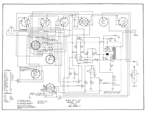
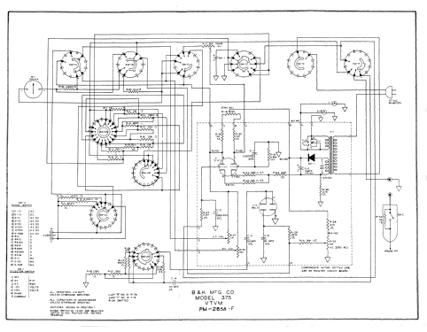
Everything upstream — the probe, the divider, the AC rectifier, the ohms battery — exists to deliver a DC voltage to one place: the signal grid of a 12AU7 dual-triode, wired as a balanced-bridge DC amplifier. [CONFIRMED tube role — service forum + schematic]. This is the textbook cathode-coupled VTVM bridge, the same balanced two-triode form that underlies most of the era’s tube VTVM designs [CONFIRMED — corroborated by the schematic and forum discussion].
2.3.1 Two triode halves, two bridge arms
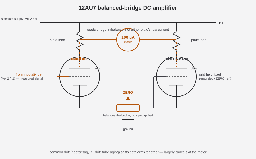
A 12AU7 is a single glass envelope containing two independent triode sections sharing a common heater. In a balanced-bridge VTVM, those two sections aren’t used as two separate amplifiers — they’re used as the two arms of a bridge circuit:
- One triode section carries the measured signal — its grid is fed from the input divider (§2), so its plate current tracks the voltage being measured.
- The other triode section is the reference arm — its grid is held at a fixed reference (typically grounded, or biased to a fixed point set by the ZERO control), so its plate current stays essentially constant regardless of what’s being measured.
Each section’s plate feeds through its own plate-load resistor up to the shared B+ supply (§6), so the two plates form the two “output” corners of a bridge whose other two corners are the common B+ rail and the common ground/cathode return. The 100 µA meter movement is connected across the bridge — between the two plates (or, depending on the exact topology, between the two cathodes) — not in series with either tube’s plate current alone. [CONFIRMED tube role and bridge concept — forum + schematic; the exact node-by-node wiring beyond the parts already verified in §2’s table is not independently re-derived here]
2.3.2 Reading imbalance, not raw current
This is the conceptual leap that makes a bridge amplifier different from a simple cathode follower or single-ended amplifier: the meter never reads either triode’s absolute plate current. It reads the difference between the two. With no input signal applied (probe tip open, or shorted to ground on the DC+ function), both triode sections — being two halves of the same physical envelope, sharing the same heater, the same B+ supply, and (ideally) very closely matched electrical characteristics — conduct almost identically. Their plate currents nearly cancel across the meter, and the bridge sits at (or very near) balance: zero net current through the meter, needle at rest.
Apply a DC voltage to the signal grid and that section’s plate current shifts away from the reference section’s — the bridge unbalances, current flows through the meter in proportion to that imbalance, and the needle deflects. The precision multiplier/attenuator string ahead of the grid (§2) is what makes that deflection track a known, calibrated fraction of the true input voltage rather than an arbitrary tube transfer curve.
⚠ Note — this is why a VTVM bridge amplifier is inherently self-compensating in a way a single-ended stage isn’t. Anything that shifts both triode sections equally — heater voltage sag, B+ drift as the selenium rectifier ages, the whole tube’s characteristics shifting together as it ages over years of use — moves both arms of the bridge together and largely cancels out of the differential reading, because the meter only ever sees the difference between the two arms, not either arm’s absolute value. A single-ended amplifier has no such built-in cancellation; every volt of supply drift shows up directly as reading error. The bridge topology is what lets a 1961 tube instrument hold calibration for decades without needing a stabilized, regulated B+ supply to match — and forum accounts do note that 375 units hold calibration well relative to some contemporaries [LIKELY — forum].
2.3.3 Cathode degeneration: a second layer of high, range-independent impedance
The schematic and forum-sourced circuit description add one more detail worth unpacking: “cathode degeneration gives the high, range-independent input impedance.” [CONFIRMED tube role — forum + schematic]. Where §2’s resistor network sets the external input resistance the test point sees, cathode degeneration is an internal property of how the signal triode section itself is wired, and the two work together rather than doing the same job twice.
“Cathode degeneration” means the signal triode’s cathode resistor is left largely unbypassed — there’s no large capacitor shorting it to AC ground the way a conventional gain stage would use to maximize amplification. An unbypassed cathode resistor creates local negative feedback: as the tube’s plate current tries to rise, the voltage it develops across the cathode resistor rises too, which makes the cathode more positive relative to the grid — effectively reducing the grid-to-cathode voltage and throttling the very current increase that caused it. That self-correcting feedback loop is what a cathode-degenerated (or cathode-follower-style) stage trades a slice of raw gain for: excellent linearity and a very stable, predictable transfer characteristic that doesn’t wander with tube-to-tube variation or minor B+ shifts. Because that stability lives inside the tube stage itself rather than depending on the specific resistor tap the range switch has selected, it holds equally well on every range — reinforcing, at the amplifier level, the same range-independence the input divider already delivers at the resistor-network level.
2.3.4 ZERO ADJUST — balancing the bridge with no input
No two triode sections, even sharing one envelope, are perfectly matched from the factory, and small mismatches drift further as the tube ages. The front-panel ZERO control exists to compensate: it adjusts the balance point of the bridge (most plausibly by trimming the reference arm’s operating point, or a shared cathode-bias element common to both sections) so that with no input applied, the meter can be set precisely to rest at its zero mark regardless of the two triode halves’ small residual mismatch. [CONFIRMED behavior class — general tube-VTVM design]
Because that balance point drifts with the tube’s own aging and, more immediately, with the temperature of the tube envelope itself, ZERO has to be reset at the start of every session after warm-up, and periodically re-checked as the tube ages — see §3.5 below and the operating procedure in Vol 4.
2.3.5 The bridge’s own calibration and trim pots
Beyond ZERO’s front-panel function, the bridge circuit carries its own internal calibration points — small-value trim potentiometers verified from the same service-forum repair thread as the divider resistors in §2:
Table 3 — resistors in §2
| Designator | Value | Role (as documented) |
|---|---|---|
| R27 | 11 kΩ | Bridge calibration/balance pot |
| R32 | 11 kΩ | Bridge calibration/balance pot |
| R30 | 15 kΩ | Bridge calibration/balance pot |
[CONFIRMED values and existence — antiqueradios.com service thread]. The thread verifies these three pots exist and their values, without spelling out a definitive one-to-one map from pot to front-panel control; the most defensible reading is that R27/R30/R32 collectively cover balance duties like front-panel ZERO trim and range-specific full-scale calibration that a bench technician would touch during a recalibration pass, rather than during normal use. [UNCERTAIN — exact pot-to-control mapping beyond what the thread states]. Vol 5’s recalibration walk-through is where a hands-on session against a known DC standard would settle which pot moves which reading.
2.3.6 Warm-up and thermal equilibrium
Like every tube instrument, the 375’s bridge balance is temperature-dependent, and the tube’s internal temperature isn’t stable the instant power is applied — the heater and the whole glass envelope need time to reach thermal equilibrium before the bridge’s zero point stops drifting. [CONFIRMED behavior class for tube VTVMs generally; the 375’s specific warm-up time in minutes is [NOT FOUND] in the sources at hand]. Practically, that means: power on, let the meter sit and settle, zero it after it’s stopped drifting rather than the instant the tube lights, and expect to nudge ZERO again periodically through a long session as ambient temperature or line voltage shifts slightly. Vol 4 covers the full warm-up and zeroing procedure step by step.
2.4 The 6AL5 AC Rectifier: RMS vs. Peak-to-Peak
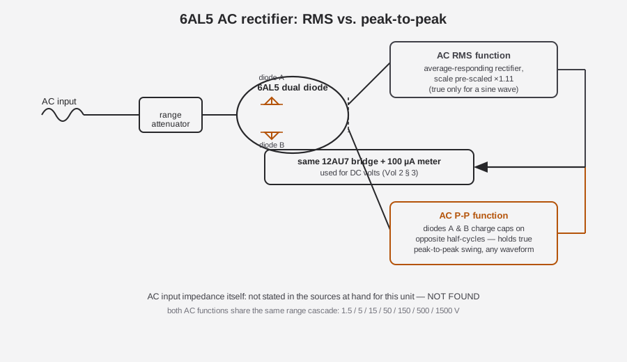
DC volts is the 12AU7 bridge’s native language — the input divider hands it a DC voltage directly. AC volts needs a translation step first: something has to turn the AC waveform into a DC level the same bridge and meter can read. That’s the 6AL5 dual-diode rectifier’s job. [CONFIRMED tube role — forum + schematic]. The 375 doesn’t just rectify AC once; per its front-panel FUNCTION SELECTOR it offers two separate AC functions — AC RMS and AC P-P (peak-to-peak) — each reading off its own scale on the drum [CONFIRMED — ad ranges + panel photo], and they get there by two different uses of the same tube.
2.4.1 A dual diode doing double duty
The 6AL5 contains two independent diode sections in one envelope — electrically simpler than the 12AU7’s triode pair, since a diode is just a rectifying junction with no grid to bias. In the 375’s AC path, the attenuated AC input (scaled down by the same style of precision resistor string used for DC, before it reaches the 6AL5) drives the diode pair, and the two diode sections are wired into two different rectifier configurations depending on which of the two AC functions is selected:
- For AC RMS, the circuit behaves as a rectifier whose DC output tracks the average value of the rectified waveform, and that output feeds the 12AU7 bridge to deflect the meter.
- For AC P-P, the circuit uses both diode halves in a peak-detecting arrangement — each half conducting on opposite half-cycles of the input, charging a capacitor (or capacitor pair) that holds the highest excursion the waveform reaches on each polarity — so the resulting DC level tracks the true peak-to-peak swing of the waveform, not an averaged approximation of it.
Either way, the 6AL5’s rectified DC output rejoins the same signal path DC volts uses: it’s applied to the 12AU7’s signal grid, and the same balanced bridge from §3 reads it out on the meter. The 6AL5 doesn’t have its own meter or its own amplifier — it’s a front-end translator that hands its result to the exact same bridge amplifier and 100 µA movement DC volts uses. [CONFIRMED tube role and shared readout path — forum]
2.4.2 RMS-calibrated (black arcs) vs. true peak-to-peak — and why they aren’t the same number
This is the distinction worth being precise about, because it’s a common source of confusion on any VTVM with both functions, not just the 375. A simple diode rectifier — the AC RMS function’s underlying mechanism — physically responds to the average of the rectified waveform, not its true RMS (root-mean-square) value. For a pure sine wave, average and RMS differ by a fixed, well-known ratio (the sine wave’s form factor, ≈1.11), so the scale can simply be pre-multiplied by that constant during manufacture and the meter will read true RMS correctly — as long as the waveform actually is a sine wave. That’s exactly what “RMS-calibrated” means on this class of instrument: it’s an average-responding circuit wearing an RMS-scaled dial, accurate for sine waves, and increasingly wrong the more a real waveform departs from a sine shape (clipped audio, switching noise, a composite video signal, anything with significant harmonic content).
The AC peak-to-peak function sidesteps that assumption entirely. By directly capturing the highest positive and lowest negative excursions the waveform reaches — rather than averaging anything — the P-P reading is accurate for any waveform shape the 6AL5 and its filter network can follow, sine or not. That’s precisely why a peak-to-peak function is useful for anything other than clean sine-wave audio: TV composite video, pulse trains, and distorted or clipped waveforms in a faulty circuit all read correctly on P-P where an RMS-calibrated scale would mislead.
Note — the 1961 ad is explicit that this AC-vs-P-P split is exactly how it presents the two functions — “RMS-calibrated black arcs vs true peak-to-peak” — rather than a single AC function with a switch-selectable multiplier. Treat the two as genuinely different rectifier configurations sharing one tube and one readout bridge, not the same measurement scaled two ways.
Table 4 — RMS-calibrated (black arcs) vs. true peak-to-peak — and why they aren't the same number
| AC function | What it physically measures | Accurate for | Full-scale ranges |
|---|---|---|---|
| AC RMS | Average of the rectified waveform, scaled ×1.11 to read RMS-of-a-sine | Sine waves; increasingly wrong on distorted/non-sinusoidal signals | 1.5 / 5 / 15 / 50 / 150 / 500 / 1500 V |
| AC P-P | True peak-to-peak excursion (positive peak to negative peak) | Any waveform shape the rectifier/filter can follow | 1.5 / 5 / 15 / 50 / 150 / 500 / 1500 V |
[Ranges CONFIRMED — 1961 ad spec block; the physical-mechanism explanation above is standard VTVM rectifier theory applied to the confirmed RMS/P-P function split, not an independently re-derived schematic trace of the 6AL5’s exact filter network]
2.4.3 Why waveform shape matters: crest factor
The gap between “reads correctly” and “reads a plausible-looking wrong number” on the AC RMS function comes down to a waveform’s crest factor — the ratio of its peak value to its true RMS value — because crest factor and form factor move together: a waveform whose crest factor departs from the sine wave’s ≈1.414 also has a form factor that departs from the sine wave’s ≈1.11, and it’s that form factor the scale is actually built around. The 375’s AC RMS scale is pre-scaled by the sine wave’s form factor (≈1.11, the fixed average-to-RMS ratio), because that’s the only waveform shape where average-responding rectification and true RMS are related by one fixed constant. Any other waveform shape has a different form factor (and a different crest factor), and the RMS-calibrated scale has no way to know that — it applies the sine-wave correction factor regardless of what it’s actually looking at.
Table 5 — Why waveform shape matters: crest factor
| Waveform | Approximate crest factor | What the AC RMS (sine-calibrated) scale does |
|---|---|---|
| Pure sine wave | ≈1.414 | Reads correctly — this is the assumption baked into the scale |
| Symmetric square wave | 1.0 | Reads high relative to true RMS — a square wave’s peak and RMS are the same value, but the scale still applies the sine-wave 1.11 averaging correction |
| Heavily clipped / distorted audio | Lower than a clean sine, and variable | Reads inconsistently — the error changes with how hard the signal is clipped |
| Narrow pulse train | Much higher than 1.414 | Reads low relative to true RMS — the meter’s average-responding rectifier badly under-represents a signal that’s mostly “off” with brief high excursions |
[General crest-factor behavior of average-responding AC rectifier instruments — standard AC measurement theory, not a 375-specific schematic derivation; the practical implication is confirmed by the ad’s own framing of “RMS-calibrated black arcs vs true peak-to-peak” as two genuinely different measurements]
Note — this is exactly why the peak-to-peak function exists on this instrument at all rather than a single “AC volts” scale. Anywhere a technician expects a non-sinusoidal signal — composite video sync pulses, a switching supply’s ripple, a clipped or distorted stage in a fault-diagnosis chase — reaching for AC P-P instead of AC RMS sidesteps the crest-factor trap entirely, because P-P never assumed a sine wave in the first place.
2.4.4 AC input impedance — a gap worth naming
Unlike DC’s clean 11 MΩ figure, the 375’s AC input impedance is not stated anywhere in the sources located for this dive [NOT FOUND]. For reference only — not a value to attribute to the 375 — the later 177 model’s spec sheet quotes roughly 11 MΩ AC / 20 MΩ DC, but that’s a different instrument with its own divider network, and carrying its number over to the 375 would be exactly the kind of invented precision this dive is trying to avoid. If a full manual scan turns up the 375’s own AC impedance figure, it belongs here and in Vol 1’s spec table; until then, treat it as an open item.
2.5 The Ohms Circuit: An Internal 1.5 V Cell
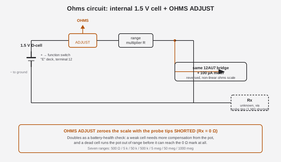
DC volts and AC volts both measure a voltage the outside world is already generating. Ohms is different — the 375 has to supply its own known reference and infer the unknown resistance from how much that reference gets divided down. It does that with the simplest possible source: a single internal 1½ volt battery. [CONFIRMED — ad: “Includes 1½ volt Battery”; a single 1.5 V D-size alkaline cell is visible in the internals photo]
2.5.1 Known current, unknown resistance
The battery, a range-selected multiplier resistor, and the unknown resistance under test (connected via the same DC-AC-Ohms probe, with its tip resistor switched out per §2) form a series loop. The current that flows around that loop — and therefore the voltage the 12AU7’s signal grid sees — depends on how large the unknown resistance is relative to the known multiplier resistor. The same balanced-bridge DC amplifier and 100 µA meter used for DC volts reads that voltage out; ohms isn’t a separate meter movement or a separate amplifier, it’s the DC bridge fed from a different source. [CONFIRMED circuit description — ad + internal photo + antiqueradios wiring detail]
Per the service-forum wiring trace: the battery’s positive terminal connects to the “E” deck of the function switch, terminal 12, and the negative terminal returns to circuit ground. [CONFIRMED — antiqueradios thread]. Because a series-resistance ohmmeter of this kind reads a voltage that moves in the opposite direction from resistance (more unknown resistance means less current flows and therefore a different — not simply proportionally larger — voltage at the sensing point, depending on exactly where in the divider it’s tapped), the ohms scale on the drum reads backward relative to the volts scales, and is compressed rather than evenly spaced across its span — commonly described as roughly logarithmic in shape, though the precise curve is a property of the specific divider topology rather than a mathematically exact logarithm. [CONFIRMED that the scale reads reversed/back — per the ad and the antiqueradios schematic-derived circuit description; the “roughly logarithmic” shape description is the conventional characterization of this class of series-ohmmeter circuit, not an independently re-derived transfer function for the 375’s exact network]
2.5.2 Reading the reversed scale — why it runs backward
The reversed, compressed shape of the ohms scale isn’t an arbitrary design choice, it falls directly out of the series circuit in §5.1. With the battery voltage E fixed and the range multiplier resistance R_mult fixed for a given range, the current around the loop is set by Ohm’s law against the total series resistance:
I = E ÷ (R_mult + Rx)
and it’s that current — or, more precisely, the voltage it develops at the point the 12AU7’s grid is tapped from — that the bridge actually reads. Look at what happens at the two extremes:
- Rx = 0 Ω (probe tips shorted): total loop resistance is just R_mult, so current is at its maximum for that range, and the sensed voltage — and the meter deflection — is at its highest point. This is exactly the calibration point OHMS ADJUST trims to, per §5.2.
- Rx → ∞ (probe tips open, or a resistance far beyond the range): total loop resistance climbs toward infinity, current falls toward zero, and the meter deflection falls toward its rest position — the same needle position DC and AC volts call “zero,” but here it means “infinite resistance,” not “no signal.”
Between those two extremes, deflection isn’t proportional to Rx — it’s proportional to 1/(R_mult + Rx), a reciprocal relationship, not a linear one. That’s what produces the characteristic ohms-scale look: the low-resistance end of the scale (near the shorted-probe calibration point) is comparatively spread out and easy to read precisely, while the high-resistance end compresses more and more of the scale’s usable range into a shrinking span of needle travel — the same “expanded low end, compressed high end” shape every series-type analog ohmmeter shares, VTVM or VOM alike. [Reciprocal relationship and resulting scale shape: standard series-ohmmeter theory, consistent with the antiqueradios schematic-derived circuit description of a reversed/back-reading ohms scale; not an independently re-derived transfer function specific to the 375’s exact multiplier network]
2.5.3 OHMS ADJUST as a battery-health check
The front-panel OHMS control (ohms-adjust) zeroes the ohms scale with the probe tips shorted together — that is, with the external resistance forced to 0 Ω, the pot is trimmed until the meter reads exactly the 0 Ω calibration point on the scale. [CONFIRMED — antiqueradios forum]
Note — why this doubles as a battery check. The current available to zero the scale at 0 Ω comes entirely from the internal 1.5 V cell. As that cell ages and its terminal voltage sags under load, the OHMS control has to be turned further and further to compensate — and eventually runs out of adjustment range before it can reach the 0 Ω mark at all. An OHMS control that won’t zero, or that zeros only at the extreme end of its travel, is a reliable field symptom of a weak or dead ohms battery — no separate battery-test function is needed because the calibration procedure is the battery test. §7 of Vol 5 covers battery-holder corrosion as the classic failure mode behind a weak reading here.
2.5.4 The seven ohms ranges
Table 6 — The seven ohms ranges
| Range (full scale) | Notes |
|---|---|
| 500 Ω | Lowest range |
| 5 kΩ | |
| 50 kΩ | |
| 500 kΩ | |
| 5 MΩ | |
| 50 MΩ | |
| 1000 MΩ (1 GΩ) | Highest range — only practical because the same 12AU7 bridge that gives DC volts its 11 MΩ headroom is doing the reading here too |
[CONFIRMED — 1961 ad spec block]
Note — the two-VTVM bench, at the circuit level. The Simpson 311-2 sitting beside the 375 on Jeff’s bench arrives at a comparable high-impedance ohms function through its own bridge and probe design, built independently by a different manufacturer. That independence is exactly what makes swapping between them a genuine cross-check rather than a repeat of the same assumption: a battery that’s sagged, a bridge that’s drifted out of balance, or a divider resistor that’s crept upward in value on one instrument won’t reproduce identically on the other, because the two circuits don’t share a battery, a bridge tube, or a resistor batch. Vol 6 works through the cross-check workflow in detail, including which kinds of disagreement point at “the meter” versus “the circuit under test.”
The top range reaching all the way to 1000 megohms is itself a demonstration of §1’s point: only an amplifying, essentially current-free input stage can usefully resolve a resistance that high, since any appreciable loading from the measuring circuit itself would swamp a resistance in the gigohm range long before you could read it.
2.6 The Selenium B+ Supply
Both the 12AU7 bridge and the 6AL5 rectifier need plate voltage — B+ — to operate at all, and that supply’s own health is part of what the bridge’s self-compensation in §3 is quietly correcting for on an ongoing basis. The 375 generates it the standard way for a 1961 tube instrument: 117 V, 50–60 Hz line power into a power transformer, stepped and rectified by a selenium rectifier. [CONFIRMED — ad + radiomuseum]
2.6.1 Why tube plates need a B+ rail at all
A triode’s plate has to sit well positive relative to its cathode for the tube to conduct a useful, controllable plate current in the first place — that positive plate supply is B+. Both bridge arms in §3 draw their plate current from the same B+ rail through their respective plate-load resistors, which is exactly why B+ drift is a common-mode disturbance to the bridge (it shifts both arms together) rather than a differential one — the self-cancellation Vol 2 §3 describes depends on both triode sections sharing one B+ source, which they do.
2.6.2 Selenium rectification — and its known hazard profile
A selenium rectifier is a stack of metal plates coated with a thin layer of selenium, which conducts current more readily in one direction than the other — a solid-state rectifying junction that predates the silicon diode and was the mainstream choice for B+ supplies through the late 1950s and into the 1960s. [CONFIRMED as the 375’s B+ device — radiomuseum: “Selenium diode for B+”]
⚠ Danger — aging selenium rectifiers are a well-known hazard in vintage tube gear generally, not a 375-specific claim: as the selenium layer degrades with age and heat cycling, forward resistance rises, the stack runs hotter under load, and a badly degraded unit can fail catastrophically — sometimes with visible smoke and a distinctive acrid, “rotten fish” odor from selenium oxide fumes, which are toxic to inhale. Any pre-1980 instrument with a selenium rectifier — this one included — should be treated per the hazardous-materials guidance in
_shared/legal_ethics.mdbefore power-up after long storage: inspect the stack visually, consider a variac-ramped power-up rather than full mains cold, and have ventilation if anything smells off. Vol 5 covers the refurb-time question of whether to keep, restore, or replace the selenium stack with a modern silicon-diode equivalent.
2.7 The RF Demodulator Probe
The base DC-AC-Ohms probe covers everything through audio frequencies, but the 375’s documentation package is titled to include two accessory RF probes — the AE-1A and PR-38 [CONFIRMED — manual title on BAMA/elektrotanya] — extending the same meter and bridge up into the RF spectrum.
2.7.1 Rectifying at the tip, not at the chassis
An RF demodulator probe puts a small rectifying element — a diode — physically inside the probe body, right at the tip, rather than routing the raw RF signal all the way back down a cable to a rectifier inside the instrument chassis. At VHF frequencies, a few inches of ordinary cable is no longer electrically “short”: its own inductance and capacitance become a significant fraction of a wavelength and would badly distort or attenuate the RF signal before it ever reached a chassis-mounted rectifier. Rectifying right at the tip converts the RF envelope to DC before it has to travel down any length of cable — and DC, unlike RF, doesn’t care about the cable’s stray reactance. What comes back down the cable to the 375’s input jack is then just another DC voltage, read out by the exact same 12AU7 bridge and meter that every other function on this instrument shares. [LIKELY — standard RF demod probe topology for the era, applied to the documented AE-1A/PR-38 pairing; the exact internal diode/filter component values for these specific probes were not independently verified]
2.7.2 What ~250 MHz means in practice
B&K’s contemporary RF demodulator probe, cataloged as the AV-1A, is rated “to 250 MHz, for most VTVMs” [LIKELY — Surplus Sales of Nebraska NOS listing]. Whether the specific AE-1A/PR-38 pair documented with the 375 carries an identical spec is [UNCERTAIN] — the relevant probe manual pages exist inside the gated BAMA/elektrotanya manual package but could not be pulled directly for this dive (see Vol 1’s Sources and Vol 3 for the gated-manual note). Treat “~250 MHz” as the right ballpark for what an RF demod probe of this class and era delivers, not a precision-verified 375-specific number.
Note — whatever DC voltage the RF probe hands back is only ever the demodulated envelope of the RF signal — a carrier’s amplitude, or an AM signal’s modulation envelope — not the RF waveform itself. This makes the RF probe a presence/level indicator for IF and RF alignment work (peak the reading while adjusting a slug or trimmer, exactly per Vol 1’s alignment use case) rather than a way to see RF waveform shape; an oscilloscope is still the right tool if waveform shape at RF matters.
2.8 Signal Flow, Start to Finish
Pulling §1 through §7 together, every function the 375 offers reduces to the same underlying move: get a DC voltage onto the 12AU7’s signal grid, without drawing meaningful current from whatever generated that voltage, and let the balanced bridge turn its unbalance into a meter deflection.
Table 7 — Signal Flow, Start to Finish
| Function | Source of the DC voltage the bridge actually reads | Front-panel controls involved |
|---|---|---|
| DC volts (DC+/DC−) | Input divider (1 MΩ probe + 10 MΩ internal, §2) directly attenuates the external DC | RANGE, FUNCTION SELECTOR (DC+ or DC−), ZERO |
| AC RMS | 6AL5 rectifies the (attenuated) AC input; average-responding output scaled to read RMS-of-sine | RANGE, FUNCTION SELECTOR (AC RMS), ZERO |
| AC P-P | 6AL5, wired as a peak detector, outputs a DC level tracking true peak-to-peak swing | RANGE, FUNCTION SELECTOR (AC P-P), ZERO |
| Ohms | Internal 1.5 V cell drives a known current through a range multiplier and the unknown Rx; the resulting voltage is read on the reversed scale | RANGE, FUNCTION SELECTOR (OHMS), OHMS (ohms-adjust) |
| DC current (DC MA) | A shunt arrangement converts the external current to a voltage the bridge can read; exact shunt topology not confirmed | RANGE, FUNCTION SELECTOR (DC MA) — hardware detail deferred to Vol 3 |
Note — the DC current function’s internal shunt arrangement is [UNCERTAIN] in the sources at hand — the schematic image available for this dive wasn’t legible enough at the DC-current section to re-derive the shunt values, and no forum thread discusses it directly. What’s confirmed is only that DC MA is one of the seven FUNCTION SELECTOR positions sharing the same meter movement as every other function; Vol 3’s hardware tour is where a shunt-resistor value, if it can be recovered from a clearer schematic scan, belongs.
Every row in that table ends at the same place: the 12AU7 balanced bridge and its 100 µA meter movement. That’s the unifying idea worth carrying into Vol 3 — the 375 isn’t five different measuring circuits sharing a case, it’s one bridge amplifier with five different front-ends feeding it, plus a demodulator probe accessory that adds a sixth. Vol 3 picks up from here with the physical hardware that implements all of this: the chassis layout, every front-panel control and jack, the complete range tables with their drum-scale windows, and the “Dynamatic” drum’s own mechanical linkage. Vol 4 turns this theory into a step-by-step operating procedure and works through the loading-error arithmetic in full. Vol 5 covers the recalibration procedure this volume’s pot map (§3.5) sets up, plus the selenium-supply and battery-holder refurb questions raised in §§5–6. Vol 6 folds all of it into a one-page cheatsheet and the two-VTVM cross-check workflow against the Simpson 311-2.
Sources
- radiomuseum.org — B&K Dynamatic 375 (tube complement: 12AU7 + 6AL5; selenium B+; schematic + photo set): https://www.radiomuseum.org/r/dynascan_k_dynamatic_375.html
- radiomuseum.org — 1961 advertisement spec block (ranges, 11 MΩ input, 100 µA movement, 1½ V ohms battery, ±1% multipliers): https://www.radiomuseum.org/images/radio/b_k_dynascan_corp/b_k_dynamatic_375_2105857.jpg
- radiomuseum.org — schematic image (title block “B&K MFG CO MODEL 375 VTVM,” drawing no. PM-285M-F): https://www.radiomuseum.org/images/schematic-medium/b_k_dynascan_corp/b_k_dynamatic_375_2095388.png
- BAMA manual archive — B&K 375 (
bk375.djvu, includes AE-1A and PR-38 RF probe documentation and the 1961 ad): http://bama.edebris.com/manuals/b&k/375 - elektrotanya — “B-K DYNAMATIC-375 TUBE VOLTMETER” service manual, 24 pp: https://elektrotanya.com/b-k_dynamatic-375_tube_voltmeter.pdf/download.html
- elektrotanya — “BK PRECISION DYNAMATIC 375 VTVM INCLUDING THE AE-1A AND PR-38 RF PROBES”: https://elektrotanya.com/bk_precision_dynamatic_375_vtvm_including_the_ae-1a_and_pr-38_rf_probes.djvu/download.html
- Antique Radio Forums — “B&K Dynamatic 375 VTVM woes” (bridge/divider resistor values R21/R25, trim pots R27/R30/R32, ohms battery wiring to function-switch “E” deck terminal 12, tube complement confirmed against the schematic): https://antiqueradios.com/forums/viewtopic.php?p=1517272, https://antiqueradios.com/forums/viewtopic.php?p=1517468, and https://www.antiqueradios.com/forums/viewtopic.php?t=3786
- Surplus Sales of Nebraska — B&K RF Demodulator Probe (AV-1A class, “to 250 MHz, for most VTVMs”): https://www.surplussales.com/items/99536/bk-rf-demodulator-probe/
- byan-roper.org (Steve Byan) — switchable VTVM probe design notes (1 MΩ isolation-resistor probe convention; contrasted with the later 277 FET Multimeter’s 100 kΩ PR-21 probe): https://www.byan-roper.org/steve/steve-at-play/antique-electronics-and-2/switchable-vtvm-probes.html