Electrostatic CRT Tester — Mark 2 · Volume 1
Electrostatic CRT Tester — Vol 1: What It Is & When to Reach for It
One box, every electrode, all set by hand — where an unknown scope/radar CRT comes to life, and which volume answers your next question
1.1 The one-sentence definition
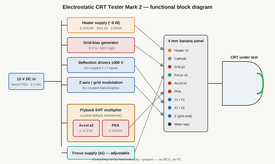
An electrostatic CRT tester is a single-box, manually-operated bench supply that produces every electrode voltage a small electrostatic-deflection, electrostatic-focus cathode ray tube needs — heater, control-grid bias, focus, accelerating anode, post-deflection acceleration, and push-pull deflection — from one 12 V DC input, each rail set by hand so you can strike, focus, deflect, and evaluate an unknown or undocumented CRT on the bench. The Mark 2 is the current open-source design by the maker at sgitheach.org.uk, released under CC BY-SA 4.0, and Jeff has built one.
That is the whole thesis of this instrument: a scope CRT or radar indicator tube is useless on the bench until roughly half a dozen different voltages — spanning three orders of magnitude, from a few volts of heater to several kilovolts of EHT — are all present, all correct, and all adjustable at the same time. Nothing else on Jeff’s bench does that in one box. This volume is the on-ramp: what the tester is, what it is emphatically not, the problem it uniquely solves, and a depth index that routes you into Vols 2–8.
1.2 What it is NOT
It is worth nailing the boundaries first, because the name invites three wrong mental models. This instrument is:
- Not an oscilloscope. A scope uses a CRT to display an external signal against a calibrated timebase. This tester has no timebase, no calibrated verticals, no trigger — it is the power and control side of a scope’s CRT circuit, exposed on a panel of knobs, with the tube under test standing in for the scope’s own display tube. You bring your own signal (or the internal set-by-hand DC levels) to see a spot or a Lissajous figure; you do not measure a waveform with it.
- Not a transconductance or emission tube tester. The Heathkit TT-1 measures mutual conductance (Gm in µmhos) of receiving valves; the Supreme 385 is an emission tester. Neither can bring a CRT to life — a CRT is not a triode/pentode with a plate curve to sweep, it is a beam-forming gun plus a deflection system plus a phosphor, and its “good/weak/dead” verdict is read visually from the spot, not from a meter needle against a roll-chart.
- Not a curve tracer. The eTracer / uTracer6 pulsed-HV tracers plot a valve’s I-V family; see the Curve Tracers overview. A CRT has no useful I-V family to trace — the diagnostic surface here is the spot on the phosphor (its brightness, focus, and position), not a current-vs-voltage curve.
- Not a magnetic-deflection / TV-CRT tester. This is the sharpest boundary and the one most likely to bite. The Mark 2 handles electrostatic deflection and electrostatic focus only. It has no deflection-yoke drive, no magnetic-focus supply, no trace-rotation coil. A magnetic-deflection television or radar-display CRT — the large-face tubes with a yoke around the neck — is out of scope entirely. Vol 8’s decision aids and the tree below both hinge on this distinction.
⚠ Scope boundary — If the tube has a yoke (a coil assembly clamped around the neck) it is magnetic-deflection and this tester will not deflect it, no matter how many volts you apply to the plates it doesn’t have. Electrostatic tubes deflect with internal plate pairs and have the deflection connections brought out as separate pins/leads. Confirm plate-pair construction before you reach for this instrument — Vol 7 catalogs which tube families qualify.
1.3 The problem it solves
Small electrostatic CRTs — the round-face scope, radar-indicator, and instrument-display tubes made from the 1930s onward (DG7/32, 2BP1, 5SP7, the CV-series, the Russian ЛO-series) — are among the hardest devices on a vintage bench to test, for three compounding reasons:
- No datasheet. Many of these tubes are military-surplus (CV-numbered), Soviet-era, or house-numbered display tubes whose datasheets never survived or never existed in English. You often do not know the heater rating, the cutoff bias, the correct accelerator/PDA split, or even the pinout with confidence.
- A fistful of simultaneous voltages. Unlike a diode you can check with an ohmmeter, or a triode you can bias with a single plate supply, a CRT needs every electrode energized at once before it does anything: heater to warm the cathode, a negative grid bias to set brightness, a focus voltage to converge the beam, an accelerating anode at a couple of kilovolts, often a PDA anode at several more, and two deflection-plate pairs. Miss or misjudge any one and you get a dead tube, a defocused smear, or a burned phosphor.
- Every rail is a hazard, and they interact. The EHT is lethal; the deflection rails are a shock hazard; and the correct value of one rail depends on the others (deflection sensitivity falls as accelerator voltage rises — see Vol 2). You cannot bring one up in isolation and walk away.
Before this tester, the sgitheach maker did exactly what most of us would: lashed together an ad-hoc rig from a couple of old Heathkit IP17 HV supplies plus a separate EHT supply, or repurposed a scope-clock power supply that “wasn’t very easy to adjust.” Jeff’s own bench has the raw ingredients too — the Heathkit IP-32 and SP-2717A HV supplies could stack up a B+ and a bias — but a stack of separate supplies with clip leads at kilovolt potentials is slow to set, hard to adjust smoothly, and unforgiving of a slip. The Mark 2 collapses that whole ad-hoc rig into one PCB, one 12 V input, one panel of knobs, with every electrode brought out to a labeled 4 mm banana jack and every rail on its own potentiometer. Vol 3 tells the full origin story (ad-hoc IP17 rig → Mark 1 → Mark 2).
1.4 The concept: one box, all electrodes, set by hand
The design philosophy is stated plainly on the maker’s page: “Simple and manually operated — no micro-controller or PC in sight!” There is no firmware, no USB, no host software, no automated sequencing. You get a board that takes 12 V DC in, generates the heater rail and the whole HV electrode stack internally (the EHT comes from a flyback transformer — the one genuinely custom component — driving a voltage multiplier adapted from a scope-clock PSU), and exposes each electrode on a banana jack with a pot to set its voltage and jumpers to configure the topology. You wire the tube’s pins to the matching jacks, warm the heater, then walk the grid, focus, accelerator, PDA, and deflection controls up by hand while watching the spot. That is the entire operating model; Vol 6 is the step-by-step bring-up sequence.
This hand-operated, MCU-free stance is deliberate and, for the target job, correct: an unknown tube with an unknown pinout is exactly the situation where you want a human in the loop, easing each rail up while watching for the first glow, ready to back off the instant something looks wrong. Automation buys you nothing when every tube is a one-off.
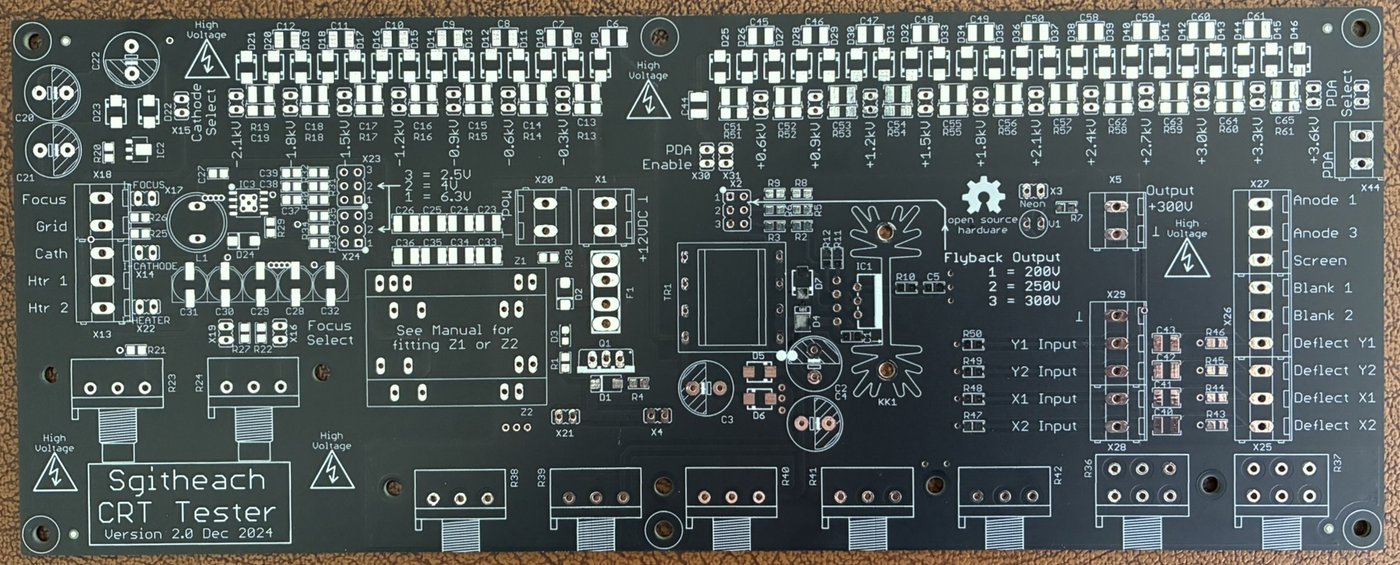
electrostatic-crt-tester-mark-2. Photo: sgitheach.org.uk, CC BY-SA 4.0.1.4.1 Quick-spec table
Every figure here is from the maker’s published specification; where the web pages don’t publish a circuit detail (the full schematic, BOM, and Gerbers live in the maker’s Dropbox), the deep-dive volumes say so rather than invent it.
Table 1 — Quick-spec table
| Parameter | Value | Notes |
|---|---|---|
| Input supply | 12 V DC | Bench PSU via 2.1 mm barrel jack |
| Heater supply | ~6 W limit | e.g. 6.3 V @ 0.6 A, 4 V @ 1.1 A, or 2.5 V @ 2 A |
| Control-grid (g1) bias | −5 V to −120 V | Relative to cathode; sets brightness / cutoff (Z electrode) |
| Focus anode | wide adjustable range | Moves the einzel-lens crossover to the screen |
| Accelerating anode (a2) | up to ~+2.2 kV | Beam energy before deflection |
| PDA (post-deflection accel.) | up to ~+5.6 kV | Brightness without stiffening the deflected beam |
| Deflection plates | −300 V to +300 V | Differential / push-pull, two orthogonal pairs |
| Deflection / mod inputs | AC-coupled X and Y + grid mod (Z) | Bring your own signal to drive the spot |
| Metering | external V and I meter provision | No built-in meters; connect your own |
| Electrode connections | 4 mm banana jacks/plugs | One per electrode, panel-mounted |
| HV generation | flyback transformer → EHT multiplier | The key custom component; scope-clock-PSU derived |
1.4.2 Hard limits (know these before you wire a tube)
Table 2 — Hard limits (know these before you wire a tube)
| Limit | Consequence |
|---|---|
| Heater capped at ~6 W | Cannot run 6.3 V @ 1.2 A heaters — over the budget |
| Single gun at a time | No simultaneous multi-gun (e.g. dual-beam) CRT operation |
| Electrostatic deflection AND focus only | No magnetic-deflection or magnetic-focus tubes |
| No trace-rotation coil testing | No provision to drive a rotation coil |
| PDA ceiling ~5.6 kV | Tubes wanting >5 kV PDA may still show a spot, but at reduced performance |
1.5 Decision tree — does this tester help?
Use this before you invest bench time. It routes on the two questions that actually determine fit: is the device electrostatic? and does it fit inside the heater/EHT envelope?
                    I have a device to test / light up
                                  │
                 ┌────────────────┴────────────────┐
                 │  Is it a cathode ray tube?       │
                 └────────────────┬────────────────┘
                         yes │                │ no ───────────┐
                             ▼                                ▼
              ┌──────────────────────────┐      Is it a cold-cathode / gas /
              │ Deflection & focus type?  │      beam-indicator device?
              └───────────┬──────────────┘      (neon, dekatron, Nixie,
         electrostatic    │    magnetic          trigger, bargraph, magic-eye,
         (plate pairs)    │    (yoke on neck)     E1T, NIMO, Geissler)
                  ┌───────┘         └──────┐            │           │
                  ▼                        ▼        yes │       no  ▼
        ┌──────────────────┐      ✗ NOT THIS TESTER     │     ✗ Wrong instrument
        │ Heater ≤ ~6 W ?  │      (needs yoke drive /    │     (use a scope, DMM,
        └────────┬─────────┘       magnetic focus —      │      tube tester, or
             yes │   │ no           a TV-CRT tester)      │      curve tracer —
                 │   └──► ✗ Over heater budget           │      see §"Not")
                 ▼                                        ▼
      ┌────────────────────┐              ✔ YES — the tester supplies an
      │ PDA need ≤ ~5.6 kV?│                 adjustable heater + negative bias
      └───────┬────────────┘                 + several hundred V to a few kV of
          yes │   │ no (marginal)             anode potential: enough to strike
              ▼   └──► ✔ works, reduced        or deflect these. → Vol 7
      ✔ IDEAL FIT — full            performance (spot dims,
        heater/focus/accel/           soft focus at high
        PDA/deflection bring-up.       sweep). → Vol 6 §limits
        → Vol 6 (bring-up),
          Vol 2 (why these rails)
The short version: an unknown round-face electrostatic scope/radar/indicator CRT within the heater and EHT envelope is the ideal fit. A magnetic-deflection TV/radar-display tube is a hard no. A Nixie, dekatron, magic-eye, or other gas/beam indicator is a happy secondary use — the tester’s adjustable heater, negative bias, and multi-kilovolt anode are exactly what those parts need to strike or deflect. A modern signal you want to measure belongs on a scope, not here.
1.6 The testable-device menagerie
Beyond CRTs proper, the same set of rails (adjustable heater + negative bias + hundreds-to-thousands of volts of anode potential) will strike or drive a surprising range of vintage indicators and beam tubes. This is a summary; Vol 7 works the whole menagerie device-by-device with connection notes.
Table 3 — The testable-device menagerie
| Device class | Examples the maker lists | What the tester provides | Photo |
|---|---|---|---|
| Electrostatic CRTs | CV5125, 5SP7, SE5F, 6ЛO1И, 09D, 130BXB31, CV1522, D10/230, CV2175, 3ЛO1И, CV2272, DG7/32, CV2320, DG7/52A, ACR10, 7ЛO1М, 2BP1, DG7/5 | Full gun + deflection stack | sg_gal5/6/8/9 |
| Cold-cathode neon | Dekatrons, Nixies (ZM1040), trigger tubes (Z700U), bargraphs, GTE175M | Striking voltage + adjustable anode | sg_dekatron, sg_zm1040, sg_z700u, sg_gte175m, sg_bargraph |
| Magic-eye / tuning indicators | EM87, 6AF6G | Heater + target/anode voltage + grid | sg_em87, sg_6af6g |
| Beam-switching | E1T (Philips decade counter) | Heater + deflection-style beam control | sg_e1t |
| NIMO tubes | (multi-segment CRT-style indicators) | Gun rails at reduced scale | — |
| Geissler tubes | (gas-discharge novelty/demo tubes) | High-voltage strike | sg_geissler |
These all work for the same underlying reason: they are hot- or cold-cathode devices that need some combination of a warmed cathode, a negative control bias, and a few hundred to a few thousand volts of anode potential to light or deflect — precisely the envelope the CRT tester already generates. It makes the instrument a general-purpose “light up a weird old tube” bench, not just a CRT jig.
1.7 Where it sits on Jeff’s bench
Jeff already runs a deep tube-era bench, but there is a CRT-shaped hole in it, and this instrument fills exactly that hole. The table maps what each neighbor does and why none of them substitutes.
Table 4 — Where it sits on Jeff's bench
| Instrument | What it does | Why it does not replace the CRT tester |
|---|---|---|
| Heathkit TT-1 | Dynamic mutual-conductance (Gm) of receiving valves | Can’t form or deflect a beam; no EHT, no deflection rails |
| Supreme 385 | Emission tube test, single-knob selection | Emission verdict only; no CRT gun/deflection support |
| eTracer / uTracer6 | Pulsed-HV valve I-V curve tracing | A CRT has no useful plate family to trace |
| Heathkit IP-32 / SP-2717A | Regulated B+ / bias / filament HV supplies | Raw voltages only — no EHT to kV, no integrated deflection/focus, slow to set as a stack |
| Bench oscilloscope | Displays signals on its own CRT | Tests nothing; it’s a consumer of a good CRT, not a tester of an unknown one |
The Mark 2 is the piece that turns “I have an unknown scope CRT in a box of surplus” into “I know its heater rating, its cutoff bias, its focus voltage, its deflection sensitivity, and whether the gun is good.” It also ties into the Television project’s mechanical/electrostatic-display work and the dekatron/Nixie material over in Electronics — Neon Ring Counters: the same tester that qualifies a scope CRT will happily light a dekatron for that project.
⚠ Danger — EHT is lethal. This box makes up to ~+5.6 kV PDA and ~+2.2 kV accelerating anode, and the EHT multiplier and AC-coupling capacitors hold charge after power-down. One-hand rule above ~50 V; bleed every HV node before you reach in; EHT-rated leads only; keep the other hand in your pocket. The ±300 V deflection and −120 V grid rails are shock hazards in their own right. Treat every CRT as an implosion hazard (handle by the body, never the neck; safety glasses), and remember some tubes emit soft X-rays at high anode voltage — don’t dwell at max PDA. Full safety discipline is in Vol 8 and the hub’s
legal_ethics.md.
1.8 Ownership status
Status: Owned (DIY-built). Jeff has built one Mark 2. The kit tier (minimum £50 bare-PCB-plus-flyback / £200 complete-electronics / £100 partial-case), build date, case variant (5 mm vs 6.35 mm acrylic), serial/provenance, and any mods are TBD pending bench photos and the MY_GEAR entry (slug electrostatic-crt-tester-mark-2). The build — kit tiers, PCB, laser-cut acrylic case, and Jeff’s own assembly log — is the subject of Vol 5, which awaits Jeff’s bench photographs.
1.9 Depth index — where each volume takes you
This is the on-ramp. The other seven volumes go deep on one facet each; jump straight to what you need.
Table 5 — Depth index — where each volume takes you
| Vol | Title / focus | Reach for it when… |
|---|---|---|
| 1 | What It Is & When to Reach for It (this volume) | You need the overview, the scope boundaries, and the decision tree |
| 2 | Electrostatic-CRT theory of operation | You want the electron’s path — cathode → grid → einzel focus lens → accelerator → deflection plates → PDA → phosphor — and the equations (cutoff bias, deflection sensitivity S ≈ Ll/2dVa, why PDA buys brightness without stiffening the beam) |
| 3 | History & lineage | You want the origin story: the ad-hoc dual-IP17-plus-EHT rig → the scope-clock-PSU adaptation → Mark 1 → Mark 2, and the open-source (CC BY-SA) release |
| 4 | Tester circuit theory | You want how the box works: the 12 V front end, heater current-limit, grid/focus/accel/PDA rail generation, the flyback EHT multiplier, and the deflection amplifiers |
| 5 | The build | You’re building or documenting a unit: kit tiers, PCB, acrylic case, hardware, and Jeff’s own build log (photographs pending) |
| 6 | Operating procedure & bring-up | You have a tube on the bench: the safe power-up sequence, reading focus/cutoff/deflection-sensitivity, and what a good/weak/gassy/shorted gun looks like |
| 7 | The testable-device menagerie | You want device-by-device connection notes: CRTs, dekatrons, Nixies, trigger tubes, bargraphs, magic-eyes, E1T, NIMO, Geissler |
| 8 | Cheatsheet, safety & comparison | You want the one-page bring-up cheatsheet, the full HV/implosion/X-ray safety discipline, and where the tester sits against the rest of the bench |
Read Vol 2 next for why these particular rails exist and how the electron gun turns them into a focused, deflected spot; go to Vol 6 when you actually have a tube clipped to the banana jacks and a hand on the potentiometers.