Electrostatic CRT Tester — Mark 2 · Volume 3
Electrostatic CRT Tester — Vol 3: History, Lineage & the Open-Source Project
From a bench full of borrowed HV supplies to an open, hand-tuned, single-box tester — the scope-clock re-use that made it, and how to get one
3.1 Why testing electrostatic CRTs was always a problem
Every other volume of this deep dive treats the Electrostatic CRT Tester — Mark 2 as an object: a circuit (Vol 4), a build (Vol 5), a procedure (Vol 6), a menagerie of devices it can light (Vol 7). This volume treats it as an answer — and to understand the answer you have to feel the problem it solves. That problem is a specific, decades-old gap on the restoration bench: there has never been a good, general way to test an electrostatic-deflection, electrostatic-focus cathode-ray tube.
Consider what Jeff already has for the rest of the vacuum-tube bench. A receiving valve — a 12AX7, a 6L6, an EL84 — drops into the Heathkit TT-1 transconductance tester or the Supreme 385 emission tester, you look up the socket and settings on a roll chart, and in a minute you have a good/weak verdict. Want the full picture instead of a verdict? Drop it into the eTracer or uTracer6 pulsed-HV curve tracer and read the whole plate family. That entire workflow rests on a century of infrastructure: standardized bases, published pin-outs, roll charts, tester settings, and — above all — datasheets.
An electrostatic CRT has almost none of that. The small round-face tubes used in oscilloscopes, radar indicators, and instrument displays — the DG7/32, the 2BP1, the 5SP7, the CV-series, the Russian ЛO-series — were built in the tens of thousands of types, many for a single military or industrial contract, and the paperwork for a great many of them simply did not survive. You pull one out of a scrapped indicator unit and you are holding an unlabeled glass funnel with a fistful of pins and no way to know, without research, what voltage the heater wants, where cutoff sits, how hard you can push the accelerator, or whether the PDA anode is spiral aquadag that wants +5 kV or nothing at all.
And even when you do know the numbers, there was never a consumer instrument built to supply them. This is the sharp historical asymmetry:
Table 1 — And even when you do know the numbers, there was never a consumer instrument built to supply them. This is the sharp historical asymmetry
| Tube class | Was there a purpose-built tester? | Why / why not |
|---|---|---|
| Receiving valves (triodes, pentodes) | Yes — thousands of models | Huge consumer/service market; every radio-TV shop had one (TT-1, B&K 707, Hickok 539) |
| TV picture tubes (magnetic CRTs) | Yes — the “CRT tester/rejuvenator” | Every TV shop tested and rejuvenated picture tubes; B&K 467/470, Sencore CR-series were standard kit |
| Electrostatic CRTs (scope/radar/indicator) | No — essentially never | Small, specialist, low-volume market; no service-trade demand ever justified a product |
The middle row is the one that stings. The television-service trade was so large that a whole product category — the CRT tester-rejuvenator, a box that measured picture-tube emission and could zap a tired cathode back to life — existed on every shop bench. But those testers speak the language of a magnetic-deflection picture tube: they light the heater, read cathode emission, check for heater-cathode shorts, and rejuvenate. They know nothing about an einzel focus lens, a pair of deflection plates, or a post-deflection-acceleration spiral. Point one at a 2BP1 and, at best, it tells you the heater is intact.
So restorers improvised. If you wanted to bring an unknown scope tube to life you built a lash-up: a heater supply, a negative-bias supply for the grid, a medium-high supply for the focus and accelerator, an EHT supply for the final anode, and some way to put a differential voltage on each deflection pair — five or six separate voltages, several of them lethal, several of them floating with respect to each other, all clipped together on the bench with test leads. It worked, but it was slow, fiddly, and genuinely dangerous. That improvised rig is exactly where this project starts.
The one-line framing. A receiving valve is a number (Gm), a picture tube is a verdict (good/rejuvenate/scrap), but an electrostatic CRT is a whole machine — heater, gun, lens, accelerator, PDA, two deflection axes — and until this project nobody sold a single box that drove all of it. The tester is the missing instrument for the missing datasheet.
3.2 The maker’s ad-hoc rig — and why it hurt
The maker at sgitheach.org.uk — a Scottish maker who ships from the Highlands, with some North-American stock held in San Diego, California — did exactly what every other electrostatic-CRT restorer did before building this instrument: assembled a rig out of whatever HV supplies were on hand. In the maker’s own account, that was “a rig made up of a couple of old Heathkit IP17 high voltage power supplies, a separate EHT power supply” — or, alternatively, an old scope-clock power supply that, in the maker’s words, “wasn’t very easy to adjust.”
Read that back slowly, because every phrase in it is a pain point, and the tester is best understood as the systematic removal of each one.
The Heathkit IP-17 is a vintage regulated HV bench supply — a close cousin of the IP-32 already in Jeff’s stable — giving a few hundred volts of adjustable B+ plus a filament winding. One of them can plausibly cover a CRT’s focus or accelerator rail. But a single electrostatic CRT needs several rails at once, at very different potentials, and referenced to a common cathode:
   WHAT ONE ELECTROSTATIC CRT ACTUALLY DEMANDS, ALL AT ONCE
   (potentials referenced to cathode; typical electrostatic scope tube)

     heater  ~6.3 V @ 0.6 A ......... low-voltage, current-limited
     grid g1  −5 V … −120 V ......... NEGATIVE, adjustable (sets cutoff)
     focus a1  several hundred V .... adjustable over a wide range
     accel a2  up to ~+2.2 kV ....... EHT
     PDA       up to ~+5.6 kV ....... higher EHT, AFTER the plates
     X plates  −300 V … +300 V ...... differential / push-pull
     Y plates  −300 V … +300 V ...... differential / push-pull
Cover that with a couple of IP-17s and a separate EHT supply and here is your afternoon:
- You are juggling several floating HV supplies at once. Two IP-17s plus an EHT brick means three chassis, three mains cords, three sets of output leads — and their grounds and references have to be tied together correctly, by hand, before anything is safe or even makes sense. Get the reference wrong and a “300 V” reading is really 300 V on top of 2 kV.
- There is no easy adjustment. The scope-clock PSU the maker also tried “wasn’t very easy to adjust” — it was built to sit at one operating point and hum along, not to be swept up and down while you hunt for a tube’s cutoff or focus. Finding focus means trimming one supply while watching the spot; on a fixed or coarsely-adjustable supply that is maddening.
- There is no integrated heater or grid. The IP-17/EHT combination gives you anode voltages. It does not naturally give you a nice current-limited heater rail or a clean, adjustable negative grid-bias supply — the two things you most want to fiddle to protect the tube and find cutoff. Those you rig up separately, adding yet more boxes and leads.
- Everything lethal is exposed on the bench. Five or six voltages, several in the kilovolt range, live on clip leads across an open bench. Every lead is a thing to bump, short, or grab. (Vol 8 makes the safety case in full; here it is enough to say the ad-hoc rig maximizes exposed HV.)
None of this is a knock on the IP-17 — it is an excellent supply, and Jeff keeps its sibling for exactly the general-purpose HV work it is good at. The point is narrower: a general HV supply is the wrong shape for the specific recurring job of lighting a CRT. The job wants one box, one reference, one set of clearly-labelled knobs, and a heater and a grid built in. That realization is the hinge of the whole story.
Callout — why “it works” is not “it’s good.” The ad-hoc rig worked: the maker tested CRTs with it for a long time. The move from Mark-nothing to Mark 1 was not about capability — the borrowed supplies could already make the voltages. It was about ergonomics and safety: collapsing six clip-lead connections and three floating chassis into one referenced, adjustable, labelled instrument. That is a recurring lesson across this whole TestEquipment hub — the Curve Tracers primer makes the same point about DIY tube tracers, where the win over “a bench supply and a meter” is integration and repeatability, not raw volts.
3.3 The key move: re-using a scope-clock power supply
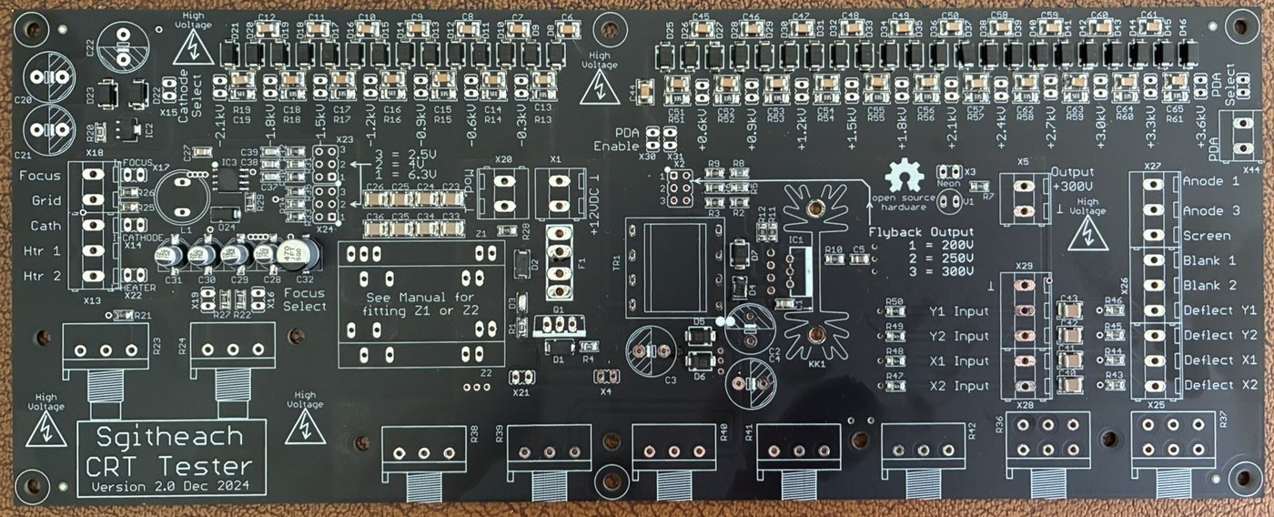
Here is the elegant part, and it is worth savouring because it is a genuinely tidy piece of engineering reuse. The maker did not design a six-rail HV supply from a blank sheet. The maker took a scope-clock power supply and adapted it onto a custom PCB with potentiometers and jumpers. That adapted supply is the CRT Tester.
To see why that is clever you have to know what a scope clock is.
3.3.1 What a “scope clock” is
A scope clock is a hobbyist clock that tells the time by drawing the digits — vector-style — on a small electrostatic CRT, so the display looks like glowing green handwriting on a little round oscilloscope face. It is a beloved corner of the vintage-electronics maker world (Jeff will recognize the aesthetic instantly from the same community that produces Nixie clocks and dekatron counters). Instead of lighting fixed segments like a Nixie or a seven-segment display, a scope clock steers a single electron beam around the screen with X and Y deflection voltages and blanks it with the grid, painting numerals stroke by stroke — exactly the way a vector display or an analog oscilloscope in X-Y mode works.
And that is the insight. To draw digits on an electrostatic CRT, a scope clock’s power supply must already generate almost every rail the CRT Tester needs:
     A SCOPE CLOCK'S PSU  ──────────────►  WHAT A CRT TESTER NEEDS
     ─────────────────────────────────     ─────────────────────────
     heater rail for the CRT ............► heater supply            ✓
     HV accelerating anode ..............► accel anode (a2)         ✓
     EHT for a bright trace .............► PDA / final anode        ✓
     deflection drive (X and Y) .........► ±deflection to the plates ✓
     grid blanking (beam on/off) ........► grid bias / Z modulation ✓
     runs from a low-voltage DC input ...► 12 V DC bench feed       ✓
The scope clock already solved “make all the CRT voltages from one low-voltage input,” because that is its whole job — it is a self-contained box that lights and steers an electrostatic CRT continuously, for years, on a shelf. The power-supply engineering to do that is the hard 80% of a CRT tester. The scope-clock PSU brought a flyback-transformer-based HV generator (the flyback is the key custom magnetic component; see Vol 4) feeding an EHT multiplier, a heater rail, and deflection drive, all referenced sensibly to a common cathode and all fed from a modest DC input.
3.3.2 What the maker added to turn a clock into a tester
A clock and a tester want opposite things from that supply. The clock wants the rails nailed to fixed values and left alone — it always drives the same CRT at the same operating point forever. A tester wants every rail adjustable and instrumented, because the whole point is to hunt for an unknown tube’s parameters and read them off. So the adaptation onto the custom PCB is essentially the conversion from “fixed and hidden” to “adjustable and exposed”:
Table 2 — A clock and a tester want opposite things from that supply. The clock wants the rails nailed to fixed values and left alone — it always drives the same CRT at the same operating point forever. A tester wants every rail adjustable and instrumented, because the whole point is to hunt for an unknown tube's parameters and read them off. So the adaptation onto the custom PCB is essentially the conversion from "fixed and hidden" to "adjustable and exposed"
| Scope-clock PSU (as-is) | What the tester adds | Why |
|---|---|---|
| Fixed heater rail for one known CRT | Current-limited, tap-selectable heater (~6 W: 6.3 V/0.6 A, 4 V/1.1 A, 2.5 V/2 A) | An unknown CRT’s heater rating is unknown — start conservative, don’t cook it |
| Fixed grid-blanking level | Adjustable −5 V to −120 V grid bias on a pot | Cutoff is a measurement you want, not a fixed drive |
| Fixed accel/focus for one tube | Wide-range focus + accel pots | Focus and accel are per-tube; you trim them live watching the spot |
| Fixed EHT for one screen | Adjustable PDA up to ~+5.6 kV | Different PDA tubes want different final-anode volts |
| Hard-wired deflection from the clock logic | AC-coupled external X/Y inputs + grid-mod (Z) input, ±300 V plate drive | Feed the tester from a signal generator to sweep a real trace |
| One hard-wired CRT | 4 mm banana jacks per electrode + jumpers | Connect any tube’s pin-out by hand; reconfigure per tube |
| No metering | Provision for external current + voltage meters | Read emission and set voltages quantitatively |
That is the “no micro-controller or PC in sight” philosophy made concrete: the intelligence that a scope clock puts in firmware (which digit to draw, where) is deleted entirely, and everything that firmware would have controlled is brought out to a pot or a jumper or a banana jack so a human sets it by hand while watching the tube. The tester is a scope clock with its brain removed and every one of its nerves brought out to the front panel.
Callout — the re-use, in one sentence. A scope clock is a power supply that already lights and steers an electrostatic CRT from a low-voltage DC input; a CRT tester is that same power supply with every fixed rail made adjustable, every node brought out to a banana jack, and the firmware thrown away. The maker did not invent the hard part — the maker recognized that the hard part was already sitting on a clock shelf, and repackaged it.
3.4 Mark 1 → Mark 2: the lineage
The tester did not spring into being fully formed. There were two production generations, on top of the ad-hoc rig that preceded both:
   LINEAGE OF THE ELECTROSTATIC CRT TESTER
   (time flows downward; not to scale)

   ┌───────────────────────────────────────────────────────────────┐
   │  AD-HOC RIG           couple of Heathkit IP17 HV supplies      │
   │  (pre-project)        + separate EHT supply                    │
   │                       — or — an old scope-clock PSU            │
   │                       "wasn't very easy to adjust"             │
   │                       • several floating HV boxes              │
   │                       • no integrated heater / grid            │
   │                       • clip leads across an open bench        │
   └───────────────────────────────┬───────────────────────────────┘
                                    │  KEY MOVE:
                                    │  adapt a scope-clock PSU onto a
                                    │  custom PCB with pots + jumpers
                                    ▼
   ┌───────────────────────────────────────────────────────────────┐
   │  MARK 1               first integrated single-box tester       │
   │  (crttester1mark1     • the scope-clock-derived design         │
   │   .html; kits          realized as one instrument             │
   │   NO LONGER SOLD)     • proved the concept on the bench        │
   └───────────────────────────────┬───────────────────────────────┘
                                    │  refinement:
                                    │  packaging, adjustability,
                                    │  kit-ability, documentation
                                    ▼
   ┌───────────────────────────────────────────────────────────────┐
   │  MARK 2   ★CURRENT★   the design this deep dive covers         │
   │  (crttester1.html)    • laser-cut acrylic case + 3D parts     │
   │                       • three kit tiers (£50 / £100 / £200)   │
   │                       • SMD pre-fitted option                 │
   │                       • CC BY-SA 4.0, fully open              │
   └───────────────────────────────────────────────────────────────┘
Mark 1 came first. It was the moment the scope-clock re-use stopped being a bench lash-up and became a designed, single-box instrument. The maker’s site keeps a Mark 1 page (crttester1mark1.html) as a historical record, but Mark 1 kits are no longer available — the maker sells only Mark 2 now. The Mark 2 page carries the plain title “Electrostatic CRT Tester - Mark 2,” and its companion build/kit document (crttester1a.html, with anchors #minimum, #complete, #case) is where the current kit tiers live.
Here honesty matters more than a tidy changelog. The site does not enumerate every Mark 1 → Mark 2 change. It would be easy — and wrong — to manufacture a bullet list of “improvements” and present them as fact. What can be said responsibly is this: a “Mark 2” of a hobbyist open-hardware project, superseding a now-discontinued Mark 1, almost universally represents refinement along a few well-worn axes, and the observable features of the shipping Mark 2 are consistent with exactly that trajectory:
Table 3 — Here honesty matters more than a tidy changelog. The site does not enumerate every Mark 1 → Mark 2 change. It would be easy — and wrong — to manufacture a bullet list of "improvements" and present them as fact. What can be said responsibly is this: a "Mark 2" of a hobbyist open-hardware project, superseding a now-discontinued Mark 1, almost universally represents refinement along a few well-worn axes, and the observable features of the shipping Mark 2 are consistent with exactly that trajectory
| Axis of refinement | What a “Mark 2” of an open-hardware tool typically improves | What is observable on Mark 2 (fact) | Confidence |
|---|---|---|---|
| Packaging / mechanics | From a bare board or improvised enclosure to a designed, repeatable case | Laser-cut 5 mm / 6.35 mm acrylic case + 3D-printed corner posts, handle, thumb screws | Observed on Mark 2 |
| Adjustability / ergonomics | More/finer front-panel controls; clearer layout | Every rail on a pot/jumper; banana-jack panel; external meter provision | Observed on Mark 2 |
| Kit-ability | From one-off to reproducible, buildable-by-others kit | Three defined kit tiers; SMD pre-fitted option; bagged/labelled parts | Observed on Mark 2 |
| Documentation / openness | Cleaner docs, formal open licence, shared design files | CC BY-SA 4.0; acrylic cutting files + BOM/Gerbers shared via the project folders | Observed on Mark 2 |
| Circuit specifics (which rails, exact values changed) | Usually some re-spin of values, protection, layout | Not enumerated by the site — do not claim specifics | Unknown — not asserted |
The disciplined reading: Mark 2 is unambiguously the kit-able, well-packaged, formally-open generation, and those are the things you can point at on the shipping product. Whether Mark 2 changed a particular resistor value or added a particular protection diode versus Mark 1 is not documented publicly, and this deep dive does not pretend otherwise. Where Vol 4 reasons about the circuit, it reasons from the published Mark 2 specification, not from an invented Mark 1-vs-2 diff.
3.5 The open-source ethos
The tester is not merely “a design someone shares.” It is a formally, deliberately open project, and the maker states both the licence and the philosophy in plain terms:
“It is fully open design and open source all released under a Creative Commons ShareAlike 4.0 International license.”
“Simple and manually operated — no micro-controller or PC in sight!”
Those two sentences are the whole ethos, and they reinforce each other. Read them together.
“Fully open design and open source … CC BY-SA 4.0.” This is not a photo of a finished box with the internals kept secret. The design files that let you reproduce and modify the instrument are released: the schematic, the BOM, the Gerber PCB files, and — a lovely touch for a laser-cut instrument — the acrylic cutting files for the case, all shared through the maker’s project folders. The CC BY-SA 4.0 licence means you are free to build it, study it, modify it, and redistribute your modifications, on two conditions: you attribute the maker, and you release your derivatives under the same share-alike licence. It is the copyleft of the hardware world — improvements flow back to the commons rather than getting enclosed.
“No micro-controller or PC in sight.” This is a design choice with real downstream consequences, and it pairs naturally with openness. Because there is no firmware and no host software:
- There is nothing to reverse-engineer or lose. The behaviour of the instrument is fully expressed in its schematic and its front-panel controls. Ten years from now there is no compiler toolchain to resurrect, no USB driver to keep working on a future OS, no signed firmware blob you cannot rebuild. A pot is a pot forever.
- It is fully repairable by inspection. Every function is a visible analog block you can trace, meter, and fix with the schematic in hand — exactly the ethic the whole TestEquipment hub is built on.
- It is trivially forkable. Want a bigger heater rail, a different case, an extra meter? The open Gerbers and the open acrylic files mean you can re-spin the board or re-cut the case and, per share-alike, publish your fork for the next person.
- It fits its user. The audience for an electrostatic-CRT tester is, almost by definition, someone comfortable with high-voltage analog electronics. For that person, “set it by hand and watch the tube” is not a limitation — it is the point. A micro-controller between the operator and the tube would add a layer of abstraction over an instrument whose entire value is direct, tactile control of a live beam.
Set against the borrowed IP-17s and the “wasn’t very easy to adjust” scope-clock PSU, the openness is the final piece of the same arc: the ad-hoc rig was un-adjustable and un-shareable; Mark 2 is fully adjustable and fully shareable. The instrument and its licence tell the same story.
Callout — provenance & attribution discipline. Everything in this deep dive — the photos, the specification, the quotes, the history — comes from the maker at sgitheach.org.uk, and every figure is used under CC BY-SA 4.0 with the credit line “Photo: sgitheach.org.uk, CC BY-SA 4.0.” The maker is not named on the site, so this dive refers to “the maker at sgitheach.org.uk” and invents no name. Two obligations ride along with the licence and Jeff should honour both on the bench and in any writeup: (1) attribute — credit the maker by the site, keep the credit line on the images; and (2) share-alike — if Jeff forks the board, modifies the acrylic files, or publishes a derivative, it must go out under the same CC BY-SA 4.0 licence. Take the openness as an obligation, not just a convenience.
3.6 Kits & how to get one
The Mark 2 is sold as kits from the maker’s shop page (shop.html), priced in GBP. There are three tiers plus assembly-on-request, and they map cleanly onto how much of the work you want to keep for yourself. Vol 5 walks the actual build; here is the acquisition map.
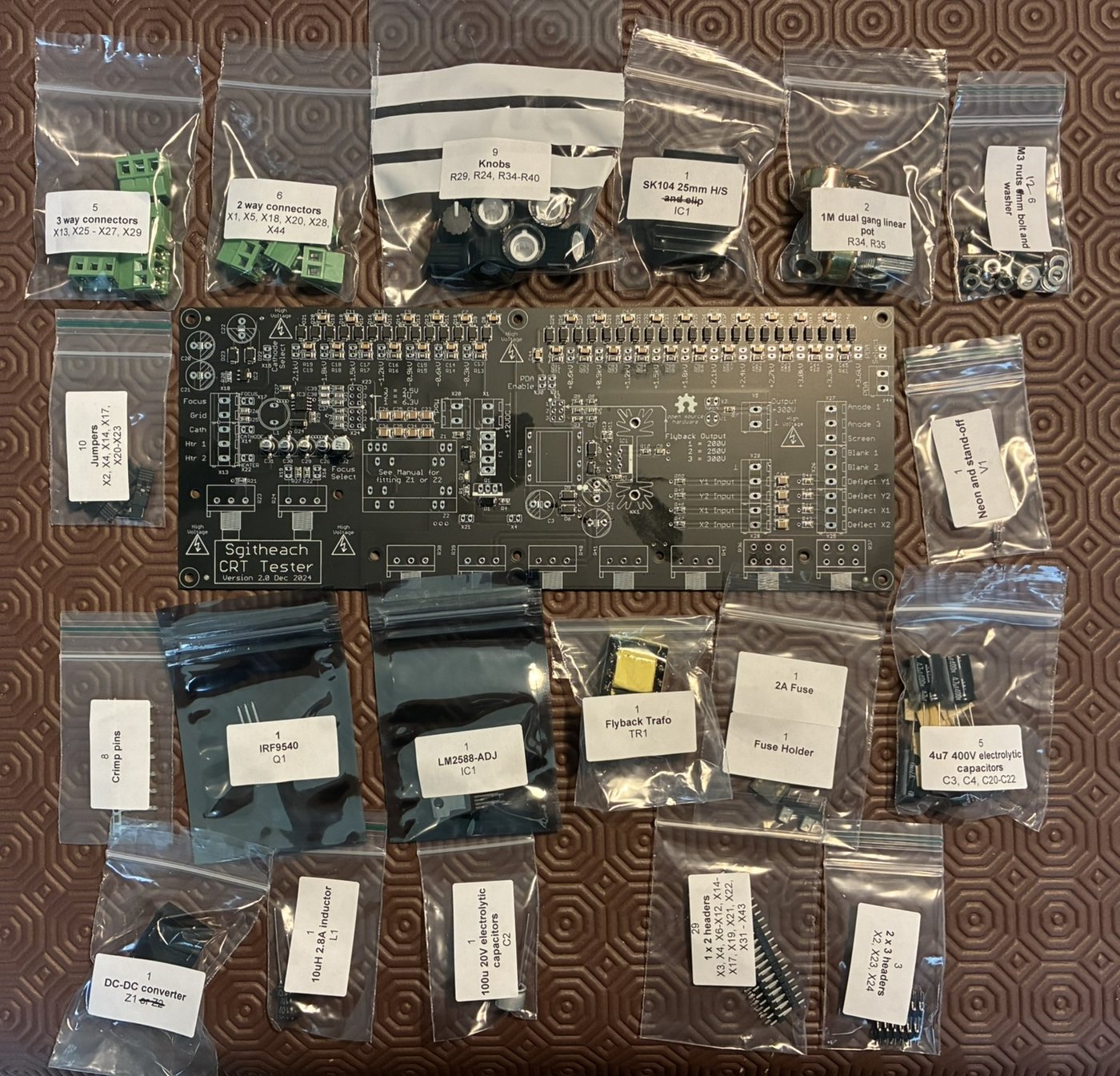
Table 4 — Kits & how to get one
| Kit | Price (GBP) | What you get | What you still source / do | Best for |
|---|---|---|---|---|
| Minimum kit | £50 | The PCB + the flyback transformer (the one hard-to-source custom magnetic part) | Everything else — all SMD and through-hole components, all hardware, and the whole case | Someone with a deep parts bin who wants the two irreplaceable pieces and will source the rest |
| Electronics (complete) kit | £200 | PCB with all SMD parts pre-fitted, plus all through-hole components and hardware in labelled bags | Solder the through-hole parts; provide/build the case | Most builders — skips the miserable SMD work, leaves the satisfying through-hole assembly |
| Partial case kit | £100 | All case components except the laser-cut acrylic — the 3D-printed corner posts, handle, thumb screws, M3 fasteners, jacks, wire | Source/cut the acrylic yourself (the cutting files are provided) | Someone who can get acrylic laser-cut locally but doesn’t want to source the small mechanical bits |
| Fully assembled & tested | On request | A finished, working instrument | Nothing — contact the maker | Someone who wants the tool, not the build |
A few practical notes from the shop page that matter when you actually order:
- The £50 and £200 tiers are the two electronics options; the £100 tier is a case option. They are not a strict ladder — a common sensible order is the £200 complete electronics (skip the SMD grief) plus the £100 partial case (get acrylic cut locally), or the £200 electronics with the full case, depending on whether you have laser-cutting access.
- The flyback is why the £50 kit exists. The flyback transformer is the key custom component (Vol 4) and the one part you cannot easily buy or wind; bundling it with the bare PCB is what makes a from-scratch build feasible at all.
- Postage is estimated at order, actual at posting. The maker quotes a Royal Mail estimate when you order and charges the real cost when shipping — and notes it is sometimes cheaper because an order may go as multiple shipments.
- Collection and regional stock. Local collection in the Highlands is available if you are nearby, and — helpfully for Jeff and other North-American buyers — some stock ships from San Diego, California, sparing the trans-Atlantic postage and customs on at least some items.
   CHOOSING A KIT TIER  (decision aid)

   Do you want to build it at all?
     NO ──────────────────────────────► "Fully assembled & tested" (on request)
     YES
      │
      ├─ Can you hand-solder SMD comfortably, and have a full parts bin?
      │     YES ─────────────────────► £50 Minimum kit (PCB + flyback), source the rest
      │     NO / rather not ─────────► £200 Complete electronics (SMD pre-fitted, bagged parts)
      │
      └─ For the case:
            Have local laser-cutting? ─► £100 Partial case + cut acrylic from the provided files
            No laser-cutting access? ──► full case option (buy the acrylic cut too)
For Jeff specifically: the built unit already on the bench means the acquisition question is settled — what remains is recording which tier was built, the case-acrylic variant (5 mm vs 6.35 mm), and any mods, into MY_GEAR under slug electrostatic-crt-tester-mark-2, and filling Vol 5’s build-log photo slots. The PHOTO_SHOPPING_LIST.md in this folder tracks those.
3.7 Where it sits in the maker community
This tester is not an isolated oddity. It sits squarely inside a living, cross-pollinating corner of the vintage-electronics world — the same corner that produces scope clocks, Nixie clocks, dekatron counters, and mechanical-television revivals — and understanding those neighbours explains both where the design came from and who it is for.
The scope-clock / vintage-display makers are the direct ancestors, as the whole of this volume has argued: the tester is a scope-clock PSU repurposed, and the people who build scope clocks are exactly the people with the electrostatic CRTs, the HV know-how, and the appetite for a tester. The genealogy runs the other way too — a well-sorted stock of tested electrostatic CRTs is precisely what a scope-clock builder needs, so the tester feeds the hobby that spawned it.
The Nixie and dekatron / neon-ring counter makers overlap heavily, and here the connection is not just cultural but literal: the tester lights their devices. Because it supplies an adjustable heater, an adjustable negative bias, and several hundred to several thousand volts of anode potential, it will strike and characterise dekatrons, Nixie tubes (e.g. the ZM1040), trigger tubes (e.g. the Z700U), and neon bargraph indicators — the exact cold-cathode parts documented in the Electronics — Neon Ring Counters dive, where dekatron counting/dividing and cold-cathode HV supplies are the whole subject. A dekatron builder who wants to sort a bag of tubes before committing them to a ring counter can do it on this tester (Vol 7 covers the full menagerie — magic-eye valves like the EM87 and 6AF6G, the Philips E1T beam-switching decade tube, NIMO tubes, Geissler tubes). The Neon Ring Counters material and this tester are two halves of the same cold-cathode bench.
The mechanical- and electrostatic-television revivalists are the third neighbour, and they connect through the Television project’s work on electron-beam displays. A scope-clock CRT and an early electrostatic TV/monitor tube are close cousins — a steered, focused, deflected beam painting a phosphor — and the tester’s ability to bring an unknown deflection tube up safely is directly useful to anyone restoring or building beam-display hardware. The Television project’s Televisor deep dive lives on the mechanical-scanning side of that family, but the electron-optics vocabulary — focus, deflection sensitivity, cutoff, PDA brightness — is shared, and this tester is the instrument that measures it.
Table 5 — Where it sits in the maker community
| Neighbouring community | Relationship to the tester | Cross-reference in the hub |
|---|---|---|
| Scope-clock builders | Direct ancestor — the tester is a scope-clock PSU repurposed; also a customer for sorted CRTs | This volume; Vol 4 (flyback EHT) |
| Nixie / dekatron / neon-ring makers | The tester lights and sorts their cold-cathode devices | Electronics — Neon Ring Counters; Vol 7 (menagerie) |
| Mechanical / electrostatic TV revivalists | Shares electron-optics; tests beam-display tubes | Television project |
| Vintage oscilloscope restorers | The tester’s home turf — sorting unknown scope CRTs | This subproject; TestEquipment hub |
That is the deepest reason the tester is open. It serves a scattered, non-commercial, mutually-helpful community of makers — scope-clock people, Nixie people, TV-revival people, scope restorers — for whom an enclosed, firmware-locked, commercially-guarded product would make no sense at all. An open, hand-tuned, forkable box is not just how this instrument happened to be built; it is the natural form for a tool that exists to serve a commons. The CC BY-SA 4.0 licence is the ethos and the community written into law.
3.8 Where this leaves us
The Electrostatic CRT Tester — Mark 2 is best understood as the end of a short, clear evolution: a real bench problem (no datasheet, no dedicated tester for electrostatic CRTs), met first by an awkward ad-hoc rig (borrowed IP-17s and a hard-to-adjust scope-clock PSU), transformed by a single clever re-use (the scope-clock power supply already made all the rails), refined across two generations (Mark 1, now retired → Mark 2, current and kit-able), and released to the commons it serves (fully open, CC BY-SA 4.0, no firmware). That is the why. Vol 4 turns to the how — the flyback-derived EHT, the grid/focus/accel/PDA/deflection supplies, and the circuit theory of the design this history produced — and Vol 5 puts the soldering iron in your hand and builds it.