Electrostatic CRT Tester — Mark 2 · Volume 6
Electrostatic CRT Tester — Vol 6: Operating Procedure & Usage
From an unknown tube on the bench to a focused, deflected spot — the safe bring-up order, the measurements it yields, and how to read what you see
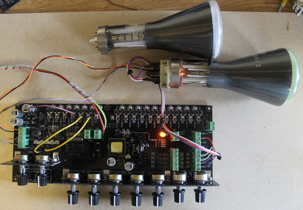
6.1 What this volume is for
Vol 2 walked one electron from the cathode to the screen and named the knob that owns each step; Vol 4 traced every supply from the 12 V barrel jack to the banana panel. This volume is the operator’s manual that sits on top of both: how you actually bring an unknown electrostatic CRT to life without killing the phosphor, the tube, or yourself, and what you can measure once the spot is up.
The Mark 2 has no processor, no interlock, no soft-start, and no “safe” default state — it does exactly what the pots and jumpers are set to at the instant you apply power. That is a feature (Vol 4’s whole premise) and a hazard in equal measure. The discipline of this volume is therefore a fixed order of operations: everything to minimum, heater first, then a dim spot, then focus, then brightness, then deflection — and the reverse on the way down, ending in a deliberate bleed of every EHT node. Follow the order and the instrument is docile. Skip a step and you can burn a phosphor in seconds or take a five-kilovolt bite from a capacitor that has been “off” for a minute.
Everything below assumes you have read the safety envelope in Vol 8 and the stored-charge warnings in Vol 4. The callouts here repeat the load-bearing ones because this is the volume where you have your hands in the neck.
6.2 Before you connect anything — identify the tube
You cannot bring up a tube you have not identified, because two numbers must be right before power reaches the heater: the heater voltage (get it wrong and you either never emit or you cook the cathode) and the electrode-to-jack mapping (get it wrong and you can put +2.2 kV where the grid expects −60 V). Everything else you can trim live; these two you must know cold.
6.2.1 What you must know before power-up
Table 1 — What you must know before power-up
| You must know | Why it is load-bearing | Where to find / how to deduce it |
|---|---|---|
| Heater voltage & current | Sets the heater tap; the tester caps at ~6 W (6.3 V @ 0.6 A / 4 V @ 1.1 A / 2.5 V @ 2 A). Over-volts cook the cathode; a 6.3 V @ 1.2 A tube is out of range entirely. | Datasheet; tube-manual family; measure cold heater resistance and infer (see below). |
| Base type & pinout | Tells you which pin is heater, cathode, g1, a1, a2, and each plate — i.e. which pin goes to which banana. | Datasheet base diagram; base type (B7G, B9A, magnal, duodecal, side-cap) narrows it hard. |
| Electrode set | Does it have a separate a1 (focus) and a2 (accel)? A PDA helix (side/top cap)? One deflection pair or two? | Datasheet; else deduce from pin count + presence of a bulb-side or top cap (see below). |
| PDA present? | If yes, the bell-side or top cap is the PDA connection and wants the +5.6 kV rail, not a2. If no, leave the PDA banana dangling and bled. | A conductive stripe/cap on the flare = PDA. Round scope/radar tubes often have it; tiny indicator tubes often do not. |
| Deflection: electrostatic? | The tester does electrostatic deflection/focus only. A tube with a deflection yoke (coils on the neck) cannot be driven here. | Plates inside the neck = electrostatic (OK). External coil yoke = magnetic (not testable). |
| Max ratings (a2, PDA, plate V) | So you know the ceiling you must not chase past — and whether the tube wants >5.6 kV PDA (works, but dim). | Datasheet; else stay conservative and stop the moment brightness is “enough.” |
6.2.2 Deducing electrode identity with no datasheet
Many of these tubes — CV-numbered British service types, Russian ЛO-series, one-off radar indicators — arrive with no datasheet you will ever find. You reason from the physical tube:
- Count the neck pins and look for caps. A base with, say, 7–12 pins plus one or two bulb-side connectors (little caps on the flare) is the classic pattern: the side caps are the final anode / PDA taken out near the screen where the voltage is highest, away from the base. A top cap on a small tube is usually the final anode too.
- Heater pins are the low-resistance pair. With a DMM on ohms, the two pins showing a low, finite resistance (a few ohms to low tens of ohms, cold) are the heater. Everything else reads open cold. That one measurement alone finds the heater and lets you infer its rating: a 6.3 V heater is typically a few ohms cold, a 2.5 V one lower still — combined with the family, it tells you the tap.
- Cathode is adjacent to the heater in the base pattern (indirectly-heated: the cathode sleeve surrounds the heater) and reads open to everything cold.
- Grid (g1) is the pin nearest the cathode in the gun stack, and in a working tube it is the electrode that extinguishes the spot when you drive it negative — you confirm it live, during bring-up, by finding which control kills the beam.
- The deflection plates come in pairs that read open to each other and to everything else; on a round-face tube they are usually the four pins in a symmetric group. You confirm X vs Y live by seeing which pair moves the spot horizontally.
- Focus (a1) vs accel (a2): if there are two anode connections of similar construction, the one that sharpens the spot when varied is a1 (focus); the one that sets overall beam energy / brightness and stiffness is a2. You sort them live, gently, starting both low.
⚠ Identify before you energize. Ring out the base cold with a DMM before the tube is anywhere near the tester: find the heater pair, confirm no electrode is shorted to another, and confirm no electrode is shorted to the heater (a heater-cathode short is a common failure and will put your heater rail onto the cathode reference). Only then build the hookup. If you cannot positively identify the heater pins and confirm the tube is electrostatic (plates, not a yoke), stop — this tester cannot safely guess for you.
6.3 The banana-jack hookup
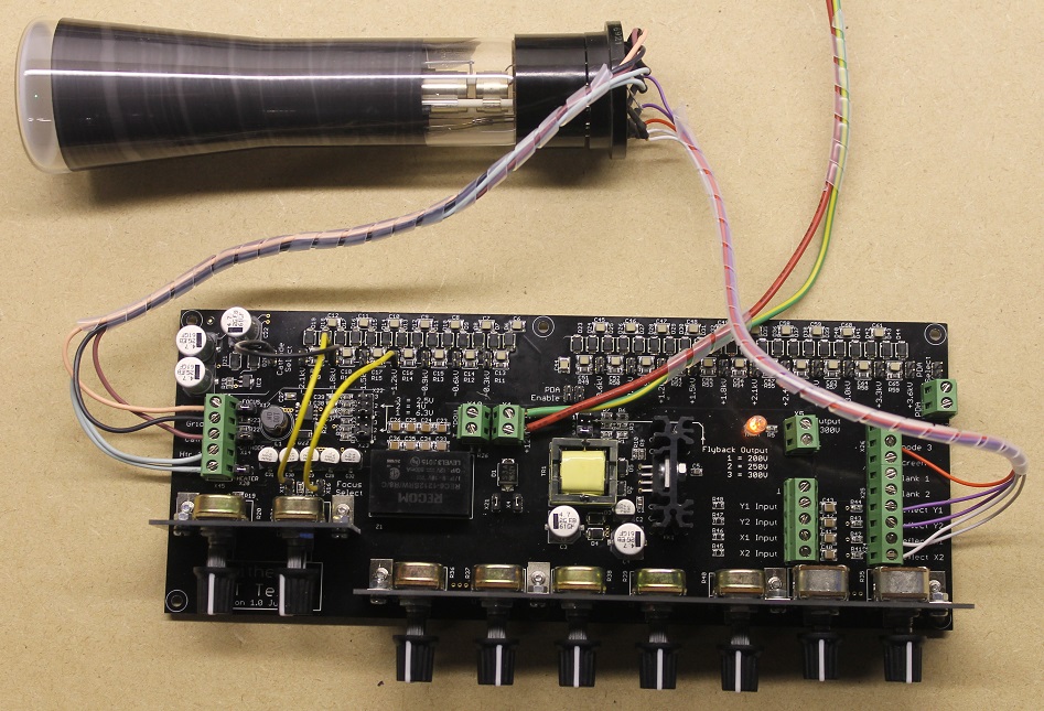
Every electrode leaves the tester on a labelled 4 mm banana jack (Vol 4). You build a harness of EHT-rated leads from those jacks to the tube’s base pins (a scrap CRT socket with flying leads, or individual clips on a de-based tube). The map below is the canonical assignment; the exact silkscreen labels are on your board (Vol 4’s controls map), but the electrode set is fixed.
6.3.1 ASCII connection map — tester banana panel → CRT electrodes
   TESTER BANANA PANEL                         CRT ELECTRODE (gun → screen)
 ┌────────────────────────┐
 │  HEATER  (2.5–6.3 V) ○──┼───────────────────►  Heater / filament  (low-Ω pair)
 │  HEATER  (return)    ○──┼───────────────────►  Heater / filament
 │                        │
 │  CATHODE / RTN       ○──┼═══════ 0 V REF ════►  Cathode  (all volts referenced here)
 │                        │
 │  GRID g1  (−5…−120V) ○──┼───────────────────►  Control grid g1  (Wehnelt)   ← Z rides here
 │                        │
 │  FOCUS a1            ○──┼───────────────────►  Focus anode a1  (einzel lens)
 │                        │
 │  ACCEL a2  (≤+2.2kV) ○──┼══ EHT ═════════════►  Accelerating anode a2
 │                        │
 │  PDA      (≤+5.6kV)  ○──┼══ EHT ═════════════►  PDA helix  (side/top cap)  — omit if no PDA
 │                        │
 │  Y+  / Y-  (±300V)   ○──┼───────────────────►  Vertical deflection plate pair
 │  X+  / X-  (±300V)   ○──┼───────────────────►  Horizontal deflection plate pair
 │                        │
 │  X-IN  Y-IN (AC)     ○──┼◄── signal gen / scope drive (AC-coupled into X/Y drivers)
 │  Z-IN  (grid mod)    ○──┼◄── blanking / intensity signal (AC-coupled onto g1)
 └────────────────────────┘
   ═══ = EHT-rated lead, treat as live for minutes after power-off
The cathode/return jack is the reference for the entire instrument — the grid’s −60 V, the a2’s +2.2 kV, and the plates’ ±300 V are all defined against it (Vol 4). Land it first and never leave it floating. The Y pair conventionally moves the spot vertically, the X pair horizontally; you confirm which physical pins are which axis during bring-up, and swap leads if the tube’s internal geometry is rotated from what you assumed.
⚠ Before the first lead touches a pin: grid to MAX NEGATIVE, all HV DOWN. Set the BRIGHTNESS/grid pot fully to its most-negative end (beam hard off, past cutoff), and the a2 ADJUST, PDA, and FOCUS pots fully down to their minimum. Deflection position pots centred, deflection drive at minimum. The instrument should be off and its EHT nodes bled while you wire. You are building the connection to a box that, the instant it powers up, will do whatever the pots say — so the pots must say “beam off, no HV” before anything is connected and before power is applied.
6.4 The safe bring-up sequence — the heart of the volume
This is the expansion of the terse order in DEVELOPMENT.md. Do it the same way every time, in this order, and narrate each step to yourself. The single governing idea: the beam should never be brighter than you need, and never sit still and bright. A stationary bright spot burns a permanent dark mark into the phosphor in seconds — an irreversible injury to a tube you cannot replace.
6.4.1 The starting state — set this before power, every time
Before you apply the 12 V, every control must be in its safe start position. This is the checklist you verify twice at step 1; nothing here is optional.
Table 2 — The starting state — set this before power, every time
| Control | Start position | Consequence if wrong |
|---|---|---|
| Grid / BRIGHTNESS pot | Fully max-negative (beam off, past cutoff) | A spot ignites the instant HV is up — bright, undeflected, burning phosphor. |
| a2 ADJUST | Fully down (minimum) | Beam energy jumps to ceiling on power-up; hard to control, arc risk on a gassy tube. |
| PDA | Fully down (minimum), or banana unconnected + bled if no PDA helix | +5.6 kV appearing uncontrolled; dangling live EHT lead. |
| FOCUS (a1) | Fully down (minimum) | Non-issue for safety but start low so you sweep up to focus. |
| Deflection drive | Zero; position pots centred | Spot parked off-screen, or slammed to one edge on power-up. |
| Heater tap | Set to the tube’s rating (never higher) | Wrong tap = no emission (too low) or a cooked cathode (too high). |
| Meters | On grid V and a2 (HV probe) before power | You bring up blind and over-shoot without them. |
6.4.2 Numbered procedure
- Everything to minimum, verify twice. Grid pot to max-negative (beam off, past cutoff). a2, PDA, focus pots fully down. Deflection drive to zero, position pots centred. Confirm the tube is wired per the map, cathode return landed, and — if the tube has no PDA helix — the PDA banana is unconnected and bled. Confirm your DMMs are on the nodes you intend to meter (grid V; a2 via a kV-rated HV probe — see Vol 4’s metering table).
- Heater first — correct tap, then warm up. Select the heater jumper/tap for the tube’s rating (never higher). Apply power. The heater should glow a dull orange within seconds; the cathode needs to reach emission temperature. Wait for warm-up — 30 s minimum, a full minute or two for larger cathodes — before expecting any beam. A cold cathode has no emission and you will be tempted to over-drive everything chasing a spot that cannot exist yet. Watch the heater current if you can meter it: a sensible steady value confirms the heater is intact and correctly tapped; zero means an open heater, a runaway means wrong tap or a short.
- Raise a2 to a low value. Bring the accel anode up gently to a modest fraction of its ceiling — a few hundred volts is plenty to start. This gives the beam energy but produces no spot yet, because the grid is still past cutoff. Meter a2 on the HV probe so you know the actual number, not the pot position.
- Back the grid off until a DIM spot just appears. Slowly advance the BRIGHTNESS/grid pot from max-negative toward zero. At some point — the cutoff bias — the spot ignites. Stop the instant you see it. You want the faintest usable spot, not a bright one. The grid voltage at which it just lights is a number worth reading and logging (see Measurements). If nothing appears even near 0 V grid at a sensible a2, do not crank a2 to the ceiling chasing it — go to the troubleshooting table; you likely have low emission or a fault.
- Focus with a1. With a dim spot up, adjust the FOCUS (a1) anode for the smallest, sharpest spot. The spot will shrink to a tight point at the focus voltage and blur either side of it. Note the a1 setting (or meter the focus voltage) — it is a tube parameter.
- Trim astigmatism against a2. If the best-focus spot is an oval or a line rather than a round dot, nudge a2 slightly and re-peak focus; the interplay between a1 and a2 sets the astigmatism (Vol 2). Iterate a1↔a2 for a round, tight spot. Keep it dim throughout.
- Add PDA for brightness — only now, and only if the tube has it. With a focused spot, raise the PDA rail to brighten the trace. PDA accelerates the beam after the plates, so it buys brightness without stiffening deflection (Vol 2’s whole point). Bring it up gradually and only as far as you need a readable trace. A tube with no PDA helix skips this — its brightness ceiling is whatever a2 gives.
- Deflect. Only now apply deflection — DC to a plate pair to move the spot, or an AC drive (signal generator / scope) into the AC-coupled X/Y inputs to sweep it. The moment the spot moves, the phosphor-burn risk drops because the energy is spread over a line, not a point. This is also when you take deflection-sensitivity numbers.
- Keep it moving or keep it blanked. Whenever you pause to think, either keep the spot in motion, drive the grid back toward cutoff to blank it, or pulse the Z input to blank. Never walk away from, or stare at, a stationary bright dot.
6.4.3 ASCII bring-up flow
  START ─ everything to MINIMUM (grid max-neg, a2/PDA/focus DOWN, deflection 0)
    │
    ▼
  HEATER on, correct tap ──► warm up 30 s–2 min ──► heater glowing, cathode hot?
    │                                                        │ no → OPEN HEATER / wrong tap → STOP, triage
    ▼ yes
  RAISE a2 to a LOW value (few hundred V, metered)
    │
    ▼
  BACK GRID OFF slowly ──────► DIM spot appears?
    │                              │ no even near 0 V grid → LOW EMISSION / fault → STOP, triage
    ▼ yes  (STOP advancing grid — faintest usable spot)
  note CUTOFF bias
    │
    ▼
  FOCUS with a1 for smallest spot ──► trim ASTIGMATISM a1↔a2 for round dot
    │
    ▼
  add PDA for brightness (only if tube has PDA helix; only as much as needed)
    │
    ▼
  DEFLECT (DC to move, AC to sweep) ──► spot moving → burn risk down → take measurements
    │
    ▼
  when done ──► POWER-DOWN sequence (grid→cutoff, HV down, heater off, BLEED, verify 0 V)
⚠ Never leave a stationary bright spot — phosphor burn is instant and permanent. A focused, undeflected, bright dot deposits its entire beam power onto a few square micrometres of phosphor and burns a dark hole there within seconds. Rules: (1) keep brightness as low as usable at all times; (2) the moment you are not actively deflecting, blank the beam — grid to cutoff, or a blanking level on Z; (3) if you must keep the beam on while you work, keep it deflected/moving so the energy spreads over a line or raster. This is the single most common way to ruin an otherwise-good tube on any CRT tester, and these tubes are irreplaceable.
6.5 Making measurements
Once a spot is up, the tester earns its keep as a measuring instrument, not just a light. Meter the electrodes per Vol 4’s metering table — grid volts on a high-Z DMM, a2/PDA on a kV-rated HV probe, plate volts on an HV-capable DMM. The core measurements:
6.5.1 Cutoff bias
The grid voltage that just extinguishes the spot at a stated a2. Bring the spot to barely-visible, then advance the grid negative until it just disappears; read the grid volts at that point. Cutoff scales with a2, so always record it with the a2 you used (e.g. “cutoff −38 V at a2 = 800 V”). It is a health/consistency check: a tube that cuts off far from its datasheet number, or drifts, or two “matched” tubes that disagree, tells you about the gun before you trust the display. (Vol 2 defines cutoff physically.)
6.5.2 Focus voltage
The a1 value that gives the sharpest spot. Meter the focus banana against cathode at best focus and log it, ideally as a focus-to-a2 ratio (a1/a2), because that ratio is roughly constant for a given gun geometry and lets you predict focus at a different a2. A tube that will not come to a tight focus at any a1 is suspect (gas, or a damaged lens electrode).
6.5.3 Deflection sensitivity
The headline geometric measurement. Apply a known differential DC voltage to one plate pair (or a measured AC and read it on a scope), measure how far the spot moves on the screen in centimetres, and compute:
S = displacement / plate voltage [cm/V], or its inverse V/cm (the deflection factor).
Do it on each axis independently. From Vol 2, the physics is S ≈ (l · L) / (2 · d · Va) — plate length l, plate-to-screen distance L, plate gap d, and accelerating voltage Va. The one term you control on the bench is Va (= a2): raise a2 and the beam is stiffer, so V/cm goes up (less deflection per volt). That is why you record sensitivity with the a2 you measured it at. Doing both axes exposes X-vs-Y asymmetry — unequal plate geometry, or a partly-open plate connection.
Table 3 — Deflection sensitivity
| Measurement | How | Record as | Notes |
|---|---|---|---|
| Cutoff bias | Advance grid negative until spot just dies | grid V @ stated a2 | Health/consistency check; always paired with a2 |
| Focus voltage | a1 for sharpest spot | a1 V, and a1/a2 ratio | Ratio ~constant across a2 for one gun |
| Deflection sensitivity, Y | Known ΔV on Y plates → measure cm | V/cm (or cm/V) @ a2 | Compare to S ≈ (l·L)/(2·d·Va) |
| Deflection sensitivity, X | Known ΔV on X plates → measure cm | V/cm @ a2 | X vs Y mismatch = geometry/connection issue |
| PDA brightness effect | Same drive, PDA off vs on | qualitative + note | Brightness up, sensitivity ~unchanged |
| Beam / cathode current | DMM in cathode return (if accessible) | mA at stated grid/a2 | Emission indicator; see below |
6.5.4 PDA brightness effect
A direct demonstration of Vol 2’s core trick. Set up a deflected trace at a fixed drive and a2. Note the brightness with PDA off, then bring PDA up and watch the trace brighten without the deflection amplitude changing — the spot does not shrink back toward centre the way it would if you had brightened by raising a2 instead. That invariance of deflection under PDA is the reason PDA tubes exist; the tester lets you see it in one A/B.
6.5.5 Painting a Lissajous / driving from a generator
The AC-coupled X and Y inputs (Vol 4) let you drive the tube like a scope in X-Y mode. Feed a signal generator into X-IN and another into Y-IN and you paint a Lissajous figure; feed the same source to both through a phase network and you get an ellipse. This is the fastest way to confirm both axes deflect cleanly and are roughly matched — a lopsided or clipped Lissajous shows an axis that is weak, non-linear, or partly open. Remember the inputs are AC-coupled: they pass no DC, so use them for sweeping/scanning, and use the direct plate jacks for a static DC deflection-sensitivity measurement.
6.5.6 Using Z to blank
Drive the Z-IN (grid-modulation) input to blank or intensity-modulate the beam. A logic-level or pulse source on Z lets you blank the retrace of a Lissajous, chop the trace, or prove the grid responds to modulation. It also gives you a hands-off way to keep a parked beam blanked. Z rides on the same g1 node as the DC grid bias (Vol 4), so it adds to whatever cutoff bias you have set.
6.5.7 Metering beam / cathode current
If the tube’s base brings the cathode out on its own pin (many do — the cathode return is a distinct pin, not strapped to the heater internally), you can put a DMM in the cathode-return lead and read beam current directly. This is a real emission measurement: at a fixed grid bias and a2, a healthy gun draws a sensible cathode current; a tired cathode draws little even wide-open. Reading cathode current vs grid bias is effectively a hand-plotted transfer curve — the same idea as the transconductance the Heathkit TT-1 measures for receiving tubes, done here for the CRT gun.
6.6 Reading tube health / troubleshooting
The tester is also a diagnostic. Most of what you learn about a tube is in how the spot behaves — or refuses to. This is the triage table; work it top-down when a bring-up does not go to plan. Cross-check symptoms against the per-device notes in Vol 7.
Table 4 — Reading tube health / troubleshooting
| Symptom | Likely cause | Action / confirmation |
|---|---|---|
| No spot at all, heater dark | Open heater; wrong/unconnected heater tap; no 12 V input | Meter heater continuity cold (should read a few Ω); check the tap jumper and the 12 V brick. Dark heater = no emission possible. |
| No spot, heater glowing | No emission (dead cathode); grid stuck past cutoff; no a2/HV; open cathode return | Confirm a2 on the HV probe; back grid toward 0 V; verify cathode-return lead. If a2 is present, grid near 0, cathode landed, and still nothing → low/no emission. |
| Dim spot even at full drive | Low emission / tired cathode | Meter cathode current (low even wide-open confirms it). Contrast with a known-good tube. Tube is weak — usable for evaluation, not a keeper. |
| Soft, blue/violet glow in the neck; won’t focus | Gas (tube has gone soft — lost vacuum) | The blue glow is ionised gas. It will never focus to a tight spot. Do not push a2/PDA up chasing focus — a gassy tube can arc. Tube is scrap for display use. |
| Spot present but won’t move on one axis | Open plate lead; that plate pair not connected; no deflection drive on that axis | Ring out the plate pair to its pins; confirm drive is actually reaching X/Y (remember X/Y inputs are AC-coupled — a DC test belongs on the direct plate jacks). |
| Spot moves on only one axis / lopsided Lissajous | One plate partly open; asymmetric plate connection; internal short | Swap known-good drive between axes to localise; compare V/cm each axis. |
| Heater lights but absolutely nothing responds | Cathode poisoning; heater-cathode short (heater rail sitting on the cathode reference) | Cold-ring heater-to-cathode: a short here is a fault. A poisoned cathode gives no emission despite a good heater. |
| Flashover / arcing / spitting at HV | Dirty HV / poor creepage on leads or base; humidity; pushing a gassy tube; a2/PDA too high for the tube | Power down and bleed immediately. Clean and dry the base and EHT leads; increase spacing/creepage; back the HV off. Never run through arcing — it damages the tube and the leads. |
| Spot present, focuses, then fades / brightness drifts | Marginal cathode; PDA collapsing under load (gas); unstable heater tap | Watch PDA on the HV probe — a level that sags when the beam draws current points at gas or a marginal EHT load. |
| Fixed dark mark on the phosphor | Phosphor burn (already damaged) | Not repairable. A cautionary result of a prior stationary bright spot — see the burn callout above. |
The pattern to internalise: dim-but-focusable = weak emission; glowing-but-unfocusable = gas; nothing-at-all = open heater or dead cathode or an HV/connection fault. Those three buckets sort most unknown tubes in the first two minutes.
6.7 Testing non-CRT devices (pointer to Vol 7)
The same three capabilities that bring up a CRT — an adjustable current-limited heater, an adjustable negative bias, and several hundred to several thousand volts of anode potential — are exactly what a whole menagerie of gas and beam devices need to strike or indicate. So the tester doubles as a bench for them, with no CRT gun involved:
Table 5 — The same three capabilities that bring up a CRT — an adjustable current-limited heater, an adjustable negative bias, and several hundred to several thousand volts of anode potential — are exactly what a whole menagerie of gas and beam devices need to strike or indicate. So the tester doubles as a bench for them, with no CRT gun involved
| Device class | What the tester supplies | Rough recipe |
|---|---|---|
| Nixie / dekatron / bargraph (cold-cathode neon) | Anode voltage above strike; no heater | Anode from a low HV tap through a limiting resistor; select cathode(s) to ground. |
| Trigger tubes (e.g. Z700U) | Anode voltage + trigger bias | Anode near-but-below self-strike; pulse the trigger electrode. |
| Magic-eye valves (EM87, 6AF6G) | Heater + anode + control bias | Light the heater at its tap; anode positive; vary the control grid to open/close the shadow. |
| E1T beam-switch | Heater + several electrode voltages | Heater tap + stepped anode/grid voltages — the tester’s multiple adjustable rails suit it. |
| NIMO / Geissler | High anode voltage | Strike from an HV tap; Geisslers just want the field. |
This is a pointer only — the bias values, strike voltages, and connection specifics for each device are in Vol 7, the testable-device menagerie. The safety rules do not relax for these: the same EHT is present, and neon/gas devices are period parts with their own voltage limits.
6.8 Power-down & make-safe
Coming down is as ordered as going up — and it ends with a step you must never skip: proving the EHT nodes are actually at zero before you touch them. Vol 4 spelled out the physics: the multiplier ladder, the ±300 V deflection rails with their AC-coupling caps, and the −120 V grid filter cap all hold their charge for minutes after power-off, because their normal loads (beam current, plate leakage, grid leakage) are all near zero. “Switched off” is not “safe.”
6.8.1 Power-down sequence
  1. GRID to CUTOFF ............ blank the beam first (protects phosphor to the last moment)
  2. PDA DOWN .................. bring the +5.6 kV rail down under control
  3. a2 DOWN .................. bring the +2.2 kV rail down
  4. DEFLECTION to zero, then HEATER OFF
  5. POWER OFF (pull the 12 V) .. no more energy going in
  6. BLEED every EHT node ...... a2, PDA, X, Y, Z, g1 → cathode return,
                                 through a kV-rated bleeder on an insulated stick
  7. VERIFY 0 V ............... meter each node against cathode return; read ~0 V
                                 on the HV probe BEFORE any bare hand goes near the neck
  8. Only now: disconnect leads / handle the tube
⚠ Bleed, then verify — do not trust the switch. After power-off, deliberately discharge every HV node to the cathode return with a proper EHT-rated bleeder (a high-value HV resistor on an insulated handle — not a screwdriver, which cratered the terminal and can flash), then confirm ~0 V with the HV probe on each of a2, PDA, X, Y, Z, and the grid before a bare hand comes near. The +5.6 kV PDA cap and the ±300 V deflection caps at the front-panel jacks are the two most likely to bite: PDA because it is the highest, the input caps because they sit right where your hand lands to unplug a signal lead. One-hand rule the entire time; EHT-rated leads only. This is the single most likely way to get hurt by this instrument (Vol 4, Vol 8).
And treat the tube itself with the same respect on the way out: it is an evacuated glass envelope — an implosion hazard. Handle it by the body, never the fragile neck; wear eye protection; and if you ran a high-anode tube near its ceiling, remember some types emit soft X-rays at high voltage — which is another reason you kept brightness (and therefore anode voltage) no higher than the job needed.
6.9 Cross-references
- Vol 2 — How an electrostatic CRT works. The physics behind every measurement here: cutoff, the einzel lens and focus, astigmatism, the deflection-sensitivity equation S ≈ (l·L)/(2·d·Va), and why PDA brightens without stiffening deflection.
- Vol 4 — Inside the tester (circuit theory). The banana panel, the jumpers-and-pots map, the metering-provision table, and the stored-charge hazards on the EHT ladder, the deflection AC-coupling caps, and the grid filter cap.
- Vol 7 — The testable-device menagerie. Per-device bring-up specifics for CRTs and for the neon / magic-eye / E1T / NIMO / Geissler devices this procedure only points at.
- Vol 8 — Cheatsheet, safety & comparison. The full HV/implosion/X-ray safety envelope this volume operates inside, and the quick-reference bring-up card.