Electrostatic CRT Tester — Mark 2 · Volume 8
Electrostatic CRT Tester — Vol 8: Cheatsheet, Safety & Where It Sits on the Bench
The laminate-ready card — every spec, the safe power-up/down order, the measurements, the full HV/implosion/X-ray safety envelope, and the niche this one box owns
8.1 What this volume is for
Vols 1–7 taught the instrument: what it is (Vol 1), how an electrostatic CRT works (Vol 2), where it came from (Vol 3), how its supplies are built (Vol 4), how to build one (Vol 5), how to operate it (Vol 6), and the whole menagerie of tubes it lights (Vol 7). This last volume is the field card — the thing you laminate and clip to the tester. It is deliberately dense: quick-facts panel, bring-up and power-down cheat-cards, a connection quick-map, a measurement cheat-card, a troubleshooting quick-table, a first-class safety section with a boxed DANGER card, a comparison that pins down exactly where this box wins and loses, and a series index. Prose is kept to the minimum needed to make each table usable; the depth lives in the volumes it cross-references.
Everything here is consistent with the terse operator card in the project’s DEVELOPMENT.md and the full bring-up procedure in Vol 6. Where a number appears, it is the verified spec from the maker (sgitheach.org.uk); where a procedure appears, it is the same order Vol 6 spells out at length.
8.2 Quick-facts panel
Everything the box is, on one card.
┌──────────────────────────────────────────────────────────────────────────┐
│  ELECTROSTATIC CRT TESTER — MARK 2            sgitheach.org.uk · CC BY-SA 4.0│
│  Manual, no micro-controller — every rail set by hand (pots + jumpers)      │
├──────────────────────────────────────────────────────────────────────────┤
│  INPUT        12 V DC bench PSU, via 2.1 mm barrel jack                     │
│  HEATER       ~6 W max — 6.3 V @ 0.6 A / 4 V @ 1.1 A / 2.5 V @ 2 A          │
│               (CANNOT run 6.3 V @ 1.2 A heaters)                            │
│  GRID g1      −5 V to −120 V (Wehnelt bias; Z-mod rides here)               │
│  FOCUS a1     wide adjustable range (einzel-lens focus anode)              │
│  ACCEL a2     up to ~+2.2 kV  ◄── EHT, lethal                               │
│  PDA          up to ~+5.6 kV  ◄── EHT, lethal (post-deflection accel)       │
│  DEFLECTION   −300 V … +300 V push-pull, X + Y pairs                        │
│  INPUTS       AC-coupled X-IN, Y-IN (deflection) + Z-IN (grid mod / blank)  │
│  METERING     provision for external current + voltage meters              │
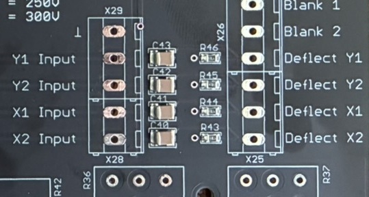
│  CONNECTIONS  4 mm banana jacks (all electrodes)                           │
│  HV SOURCE    flyback transformer → EHT multiplier (custom part)           │
│  DOES NOT DO  magnetic deflection/focus · yokes · trace-rotation coils     │
│               · >6 W heaters · >1 gun at a time · (>5 kV-PDA tubes = dim)   │
├──────────────────────────────────────────────────────────────────────────┤
│  KITS  Minimum £50 (PCB+flyback) · Complete electronics £200 (SMD fitted)   │
│        · Partial case £100 (no acrylic) · assembled: on request             │
└──────────────────────────────────────────────────────────────────────────┘
Full spec derivation is in Vol 1 and the supply-by-supply theory in Vol 4; kit tiers and the build in Vol 5.
8.3 Bring-up cheat-card (laminate this)
The safe power-up order, condensed from Vol 6 and mirroring DEVELOPMENT.md. Do it the same way every time. The one governing rule sits at the top of the card.
┌──────────────────────────────────────────────────────────────────────────┐
│  BRING-UP — SAFE ORDER          RULE: beam never brighter than needed,     │
│                                        never sitting still and bright.     │
├──────────────────────────────────────────────────────────────────────────┤
│  0  IDENTIFY the tube cold  — ring out base with DMM: find heater pair     │
│     (low Ω), confirm nothing shorted electrode↔electrode or ↔heater.       │
│     Confirm it is ELECTROSTATIC (plates, not a yoke). Know heater V.       │
│  1  EVERYTHING TO MINIMUM (verify twice):                                  │
│        grid → MAX NEGATIVE (beam off, past cutoff)                         │
│        a2 · PDA · FOCUS → fully DOWN                                       │
│        deflection drive → 0 · position pots → centred                     │
│        no-PDA tube → PDA banana UNCONNECTED + BLED                         │
│        meters on grid-V and a2 (kV HV probe)                              │
│  2  HEATER FIRST — select correct tap, apply 12 V, warm 30 s – 2 min.     │
│        heater glows dull orange; sensible steady current = tap OK.        │
│  3  RAISE a2 to a LOW value (few hundred V, metered).                      │
│  4  BACK GRID OFF slowly → STOP the instant a DIM spot appears.            │
│        (that grid V = CUTOFF — log it with the a2 used)                    │
│  5  FOCUS with a1 for smallest, sharpest spot.                             │
│  6  TRIM ASTIGMATISM — nudge a2, re-peak a1, iterate → round dot.          │
│  7  ADD PDA for brightness — only now, only if the tube has a PDA helix,   │
│        only as far as you need a readable trace.                          │
│  8  DEFLECT — DC to a plate pair to move; AC into X/Y-IN to sweep.         │
│        (spot moving = burn risk drops = take measurements)                 │
│  9  KEEP IT MOVING OR BLANKED whenever you pause. Never a static bright dot.│
└──────────────────────────────────────────────────────────────────────────┘
┌──────────────────────────────────────────────────────────────────────────┐
│ POWER-DOWN & MAKE-SAFE "Switched off" is NOT "safe." │
├──────────────────────────────────────────────────────────────────────────┤
│ 1 GRID → CUTOFF (blank the beam first — protects phosphor) │
│ 2 PDA DOWN (bring +5.6 kV rail down under control) │
│ 3 a2 DOWN (bring +2.2 kV rail down) │
│ 4 DEFLECTION → 0, then HEATER OFF │
│ 5 POWER OFF — pull the 12 V │
│ 6 BLEED every EHT node → cathode return, via kV-rated bleeder on an │
│ insulated stick: a2 · PDA · X · Y · Z · g1 │
│ 7 VERIFY 0 V — meter each node vs cathode return on the HV probe │
│ BEFORE any bare hand goes near the neck │
│ 8 Only now: disconnect leads / handle the tube (by the BODY, not neck) │
└──────────────────────────────────────────────────────────────────────────┘⚠ The multiplier ladder, the ±300 V deflection AC-coupling caps, and the −120 V grid filter cap hold kilovolts for minutes after power-off — their normal loads (beam, plate leakage, grid leakage) are all near zero, so nothing bleeds them for you. Bleed every node, then verify with the HV probe. Do not trust the switch. See Vol 4 for the stored-charge physics and Vol 6 for the full sequence.
8.4 Connection quick-map
Electrode → banana jack → typical starting setting. The cathode/return jack is the reference for the entire instrument — land it first, never leave it floating. EHT-rated leads on every ═══ node; treat them as live for minutes after power-off. Full ASCII panel map is in Vol 6, the controls map in Vol 4.
Table 1 — Connection quick-map
| CRT electrode (gun → screen) | Banana jack | Typical setting / range | Notes |
|---|---|---|---|
| Heater / filament (low-Ω pair) | HEATER + HEATER-RTN | tube’s tap: 6.3 V @ 0.6 A / 4 V @ 1.1 A / 2.5 V @ 2 A | ≤6 W; never over-volt; warm 30 s–2 min |
| Cathode | CATHODE / RTN ═══ 0 V ref | 0 V — the reference for everything | Land first; distinct pin lets you meter beam current |
| Control grid g1 (Wehnelt) | GRID g1 | −5 V … −120 V; start MAX-NEGATIVE | Z-mod / blanking rides on this node |
| Focus anode a1 (einzel) | FOCUS a1 | wide range; start DOWN, sweep up to focus | log a1/a2 ratio |
| Accelerating anode a2 | ACCEL a2 ═══ EHT | up to +2.2 kV; start DOWN | meter on kV HV probe |
| PDA helix (side/top cap) | PDA ═══ EHT | up to +5.6 kV; start DOWN, add last | omit + bleed if tube has no PDA |
| Vertical plates | Y+ / Y− | ±300 V push-pull; start centred | DC here for static deflection-sens |
| Horizontal plates | X+ / X− | ±300 V push-pull; start centred | DC here for static deflection-sens |
| — (drive) | X-IN / Y-IN (AC-coupled) | signal-gen / scope sweep drive | passes no DC — sweeping only |
| — (drive) | Z-IN (AC-coupled) | blanking / intensity pulse onto g1 | adds to the DC grid bias you set |
8.5 Measurement cheat-card
Each headline measurement in 2–3 steps. Meter grid volts on a high-Z DMM, a2/PDA on a kV-rated HV probe, plate volts on an HV-capable DMM. Physics behind each is in Vol 2; the long form is in Vol 6.
Table 2 — Measurement cheat-card
| Measure | Steps | Record as | Key reminder |
|---|---|---|---|
| Cutoff bias | ① bring spot barely visible ② advance grid negative until it just dies ③ read grid V | grid V @ stated a2 | Cutoff scales with a2 — always log the a2 you used |
| Focus voltage | ① get a dim spot up ② adjust a1 for smallest, sharpest dot ③ meter focus vs cathode | a1 V, and a1/a2 ratio | Ratio ≈ constant for one gun → predicts focus at other a2 |
| Deflection sensitivity | ① known ΔV on one plate pair ② measure spot travel in cm ③ compute | V/cm (or cm/V) @ a2 | S ∝ 1/Va — raise a2 ⇒ stiffer beam ⇒ MORE V/cm (less deflection/volt). Do X and Y separately |
| PDA effect | ① fixed drive + a2, note brightness PDA-off ② raise PDA ③ compare | qualitative A/B | Trace brightens without deflection amplitude changing — the whole point of PDA |
| Beam / cathode current | ① DMM in cathode-return lead ② fixed grid + a2 ③ read mA | mA @ stated grid/a2 | Real emission number; low even wide-open = tired cathode |
   DEFLECTION SENSITIVITY — the S ∝ 1/Va reminder
   ┌──────────────────────────────────────────────────────────┐
   │   S ≈ ( l · L ) / ( 2 · d · Va )                          │
   │       l  = plate length      L = plate-to-screen distance │
   │       d  = plate gap         Va = accelerating volts (a2) │
   │                                                            │
   │   Only Va is yours to turn on the bench.                   │
   │   ▲ a2  →  ▲ V/cm  (stiffer beam, less deflection/volt)    │
   │   So RECORD sensitivity WITH the a2 you measured it at.    │
   └──────────────────────────────────────────────────────────┘
8.6 Troubleshooting quick-table
Condensed triage from Vol 6. Work it top-down. The three buckets to internalise: dim-but-focusable = weak emission · glowing-but-unfocusable = gas · nothing-at-all = open heater / dead cathode / HV-or-connection fault.
Table 3 — Troubleshooting quick-table
| Symptom | Likely cause | Fix / confirm |
|---|---|---|
| No spot, heater dark | Open heater · wrong/unconnected tap · no 12 V | Cold-ring heater (few Ω) · check tap jumper + brick |
| No spot, heater glowing | Dead cathode · grid stuck past cutoff · no a2 · open cathode return | Confirm a2 on HV probe · back grid toward 0 · verify return |
| Dim even at full drive | Low emission / tired cathode | Meter cathode current (low wide-open confirms) · weak tube |
| Blue/violet neck glow, won’t focus | Gas (lost vacuum) | Never chase focus with a2/PDA — arc risk · tube scrap for display |
| Spot won’t move, one axis | Open plate lead · axis not driven | Ring out plate pair · remember X/Y-IN are AC-coupled — DC test on direct jacks |
| Lopsided / one-axis Lissajous | Plate partly open · asymmetric connection · internal short | Swap drive between axes · compare V/cm each |
| Heater lights, nothing responds | Cathode poisoning · heater-cathode short | Cold-ring heater↔cathode — a short is a fault |
| Flashover / arcing / spitting | Dirty HV / poor creepage · humidity · gassy tube · HV too high | Power down + bleed NOW · clean/dry base + leads · more spacing · back HV off |
| Focuses then fades / drifts | Marginal cathode · PDA sagging (gas) · unstable tap | Watch PDA on probe — sag under beam current = gas/marginal load |
| Fixed dark mark on phosphor | Phosphor burn (already damaged) | Not repairable — the price of a prior static bright spot |
8.7 Safety — the full envelope
This is a first-class section, not a footnote. This box makes lethal EHT and drives an evacuated glass tube; two independent ways to be seriously hurt sit on the bench at once. The tool-agnostic bench-discipline rules are in the hub’s legal_ethics.md; the instrument-specific envelope is below.
┌════════════════════════════════════════════════════════════════════════════┐
║                          ⚠  D A N G E R  ⚠                                  ║
║   EHT IS LETHAL — up to +5.6 kV (PDA) and +2.2 kV (a2).                      ║
║   Capacitors HOLD kilovolts for MINUTES after power-off.                     ║
║                                                                             ║
║   • ONE HAND ONLY above ~50 V — other hand in your pocket.                   ║
║   • BLEED every HV node (a2·PDA·X·Y·Z·g1) to cathode return, then VERIFY     ║
║     0 V on the HV probe BEFORE any bare hand goes near the neck.             ║
║   • EHT-RATED leads only. Never a screwdriver as a bleeder.                  ║
║   • The CRT is an IMPLOSION hazard — handle by the BODY, never the neck;     ║
║     wear safety glasses; don't nick or scratch the neck glass.               ║
║   • SOFT X-RAYS at high anode voltage — minimise time at max PDA.            ║
║   • ±300 V deflection and −120 V grid are shock hazards too. Heater is hot.  ║
└════════════════════════════════════════════════════════════════════════════┘
8.7.1 EHT — the lethal one
Up to +5.6 kV PDA and +2.2 kV a2, and — the trap — those potentials do not vanish when you flip the switch. The EHT multiplier ladder, the ±300 V deflection AC-coupling caps, and the −120 V grid filter cap all sit on near-zero normal loads, so they retain their charge for minutes (Vol 4). The rules:
- One-hand rule above ~50 V. Keep the other hand in your pocket so no current path can cross your chest. Every reach into a powered — or recently-powered — instrument is one-handed.
- Bleed every HV node, every time. Discharge a2, PDA, X, Y, Z, and g1 to the cathode return through a kV-rated bleeder resistor on an insulated handle — never a bare screwdriver (it craters the terminal and can flash over). The +5.6 kV PDA cap and the front-panel deflection input caps are the two most likely to bite: PDA because it is the highest voltage, the input caps because they sit exactly where your hand lands to unplug a signal lead.
- Verify, don’t assume. After bleeding, meter each node against cathode return on the HV probe and confirm ~0 V before a bare hand goes anywhere near the neck.
- EHT-rated leads only. Standard test leads are not rated for these potentials; a lead flashing over at 5 kV is its own hazard.
8.7.2 CRT implosion
The tube is an evacuated glass envelope — atmospheric pressure is trying to collapse it, and a crack lets it implode, then spray glass outward on the rebound. Handle it by the body, never the fragile neck; the neck is where the gun and its glass seals are, and it is thin. Do not nick, scratch, or clamp the neck. Wear safety glasses whenever a tube is on the bench. A de-based or cracked-base tube is especially fragile at the pin seals.
8.7.3 Soft X-rays
At high anode voltage, some tube types emit soft X-rays — the same physics that made high-voltage colour-TV shadowmasks a regulated concern. This tester can reach +5.6 kV PDA, comfortably into the range where certain tubes produce measurable soft radiation. Mitigation is time and distance: minimise time at maximum PDA, run no brighter (and therefore no higher-anode) than the job needs, and do not park a high-anode tube at full ceiling while you go do something else. This is another reason the operating rule is “never brighter than needed.”
8.7.4 The lesser hazards — still real
- ±300 V deflection and −120 V grid are ordinary shock hazards on their own; the fact that the kV rails dominate the discussion does not make a few hundred volts safe.
- Hot heater. The heater and cathode run at real temperature; do not touch a tube’s neck or base immediately after a run.
- Phosphor burn is a tube-damage reminder, not a personal-safety one, but it belongs on the card because it is the single most common way to ruin an irreplaceable tube: a static bright dot burns a permanent dark mark into the phosphor in seconds. Keep the beam low, deflected, or blanked at all times (see the bring-up card, rule at top).
8.8 Comparison — where it wins and where it loses
The niche in one sentence: this is the only thing that brings an electrostatic scope/indicator CRT to life on the bench. Everything else either supplies the wrong thing, displays without supplying, or targets a different tube family entirely. The decision table:
Table 4 — The niche in one sentence: this is the only thing that brings an electrostatic scope/indicator CRT to life on the bench. Everything else either supplies the wrong thing, displays without supplying, or targets a different tube family entirely. The decision table
| Alternative | What it does well | Why it can’t replace the CRT tester |
|---|---|---|
| Maker’s old ad-hoc rig (2× Heathkit IP17 HV supplies + separate EHT + scope-clock PSU) | Can, in principle, stack up the rails a CRT needs | Several supplies at kV clip-leaded to a common cathode: slow to set, hard to adjust smoothly, unforgiving of a slip — the exact pain the Mark 2 was built to end (Vol 3) |
| Bench scope in X-Y mode | Displays an X-Y trace beautifully | A scope displays — it cannot supply the heater, grid bias, focus, +2.2 kV accel, or +5.6 kV PDA the tube-under-test needs. Wrong side of the problem entirely |
| Transconductance / emission valve tester (Heathkit TT-1, Supreme 385) | Fast good/weak/dead on receiving valves (Gm in µmhos / emission) | A CRT is a beam-forming gun + deflection + phosphor, not a triode/pentode with a plate curve. No socket, no roll-chart, no EHT, no deflection — useless on a CRT (Vol 1) |
| Pulsed-HV curve tracers (eTracer, uTracer6, uTracer NXT) | Full I-V plate family of a valve, SPICE export | Characterise a valve’s conduction; they don’t form a focused beam, deflect it, or drive a phosphor. Different measurement, different tube class |
| Commercial CRT rejuvenator / tester (TV picture-tube type) | Rejuvenates / tests magnetic-deflection TV picture tubes | Built for magnetic-deflection, magnetic-focus TV tubes with yokes — the opposite of the small electrostatic scope/radar/indicator tubes this box exists for |
| Electrostatic CRT Tester — Mark 2 | Supplies every electrode an electrostatic CRT needs from one 12 V rail; measures cutoff, focus, deflection sensitivity, PDA effect; also lights neon/magic-eye/E1T/NIMO/Geissler (Vol 7) | Limits: ≤6 W heater, one gun at a time, electrostatic-only, PDA ≤5.6 kV. Within that envelope, nothing else on the bench does the job |
The through-line: a valve tester and the curve tracers work the receiving-valve side of the vacuum-tube bench; the HV supplies provide raw voltages; a scope provides a display. The CRT tester is the one instrument that integrates supply-every-rail-plus-deflect-plus-focus into a hand-tuned box aimed squarely at the electrostatic CRT — the tube none of the others can even socket.
8.9 Where it sits on Jeff’s bench
The Mark 2 fills the one gap in an otherwise complete vacuum-tube bench: nothing else Jeff owns brings a CRT to life. It pairs naturally with the HV supplies (as a reference for what a stack-of-supplies rig would demand), sits alongside the tube-era testers as the CRT-specific member of that family, and feeds the display-history work in the Television project.
| Neighbour on the bench | Relationship |
|---|---|
| Heathkit IP-32 / SP-2717A HV supplies | The raw B+/bias/filament rails that the old ad-hoc rig stacked; the Mark 2 supersedes that lash-up but the supplies remain the bench’s general HV source |
| Heathkit TT-1 · Supreme 385 | The receiving-valve testers; the CRT tester is the CRT-specific sibling — same era, complementary coverage |
| eTracer · uTracer6 · uTracer NXT | Pulsed-HV valve curve tracers; characterise conduction where the CRT tester characterises a beam |
| Television project | The electrostatic-display and mechanical-TV work this tester directly supports — bringing up indicator and scope tubes for that program |
| Electronics — Neon Ring Counters | Dekatron / Nixie material; the tester doubles as a bench for those cold-cathode devices (Vol 7) |
In practice: reach for the valve testers for a receiving tube, the curve tracers for its full plate family, the HV supplies for a raw bench rail — and the Mark 2 the moment a small round-face electrostatic CRT, a dekatron, a Nixie, a magic-eye, an E1T, a NIMO, or a Geissler tube lands on the bench and needs to be lit and read.
Glossary
Table 5 — Glossary
| Term | Meaning |
|---|---|
| Wehnelt | The control grid (g1) cylinder around the cathode; its negative bias (−5…−120 V here) throttles beam current → brightness, and past cutoff blanks the beam. The Z-axis electrode |
| Einzel lens | Unipotential electrostatic lens formed by the accel/screen grid and focus anode (a1); varying a1 moves the beam crossover to the screen → focus |
| Cutoff | The grid bias that just extinguishes the spot at a given a2; scales with a2, so always logged as a pair |
| PDA | Post-Deflection Acceleration — a helical aquadag anode after the deflection plates (≤+5.6 kV here) that adds brightness without stiffening the beam through the plates, so deflection sensitivity is preserved |
| Aquadag | Colloidal-graphite conductive coating inside the bulb; forms the final-anode / PDA electrode and collects secondary electrons |
| Deflection sensitivity | Spot travel per volt across a plate pair (cm/V), or its inverse the deflection factor (V/cm); S ≈ (l·L)/(2·d·Va) — falls as accelerating voltage Va rises |
| EHT | Extra-High Tension — the kilovolt anode rails (here a2 ≤+2.2 kV, PDA ≤+5.6 kV); lethal, and stored in capacitance after power-off |
| Flyback | The transformer (from the scope-clock PSU lineage) that steps 12 V up to EHT via a multiplier; the tester’s key custom part (Vol 4) |
| Dekatron | Cold-cathode neon counting/dividing tube with a ring of cathodes; the tester lights and steps it (Vol 7) |
| Magic eye | Tuning-indicator valve (EM87, 6AF6G) whose fluorescent shadow-angle shows a control voltage; heater + anode + bias from the tester |
| E1T | Philips beam-switching decade counter tube — a mini electron-beam device the tester’s multiple rails suit |
| Geissler | Early gas-discharge tube that glows in an applied field; the tester just supplies the striking voltage |
8.10 Series index
The complete 8-volume deep dive, one line each.
Table 6 — Series index
| Vol | Title | Purpose |
|---|---|---|
| 1 | What It Is & When to Reach for It | The one-box pitch, the spec at a glance, the niche vs the rest of the bench, and a map to the series |
| 2 | How an Electrostatic CRT Works | One electron from cathode to phosphor — cathode, Wehnelt/cutoff, einzel focus, accel, deflection (S∝1/Va), PDA — and which knob owns each step |
| 3 | History, Lineage & the Open-Source Project | The ad-hoc IP17 rig → scope-clock-PSU re-use → Mark 1 → Mark 2; the open CC-BY-SA project and how to get one |
| 4 | Inside the Tester — Circuit Theory | 12 V in → every rail out: heater limiter, grid/focus supplies, flyback EHT multiplier, ±300 V deflection, AC-coupled inputs, metering, stored-charge hazards |
| 5 | The Build — Kits, PCB, Case & Jeff’s Unit | Which kit tier, what you solder, the acrylic case, wiring the banana panel — and tjscientist’s own build log |
| 6 | Operating Procedure & Usage | Identify the tube → safe bring-up order → measurements (cutoff, focus, deflection sensitivity, PDA) → reading tube health → power-down & make-safe |
| 7 | The Testable-Device Menagerie | Per-device recipes: electrostatic CRTs and the neon / magic-eye / E1T / NIMO / Geissler devices the tester also lights |
| 8 | Cheatsheet, Safety & Where It Sits on the Bench | This card: quick-facts · bring-up/power-down · connection & measurement cheat-cards · troubleshooting · full safety envelope · comparison · glossary · index |
8.11 Cross-references
- Vol 1 — the spec-at-a-glance and the niche this box owns; the source of the comparison logic expanded here.
- Vol 2 — the physics behind every measurement on the cheat-card: cutoff, focus, S ≈ (l·L)/(2·d·Va), and why PDA brightens without stiffening deflection.
- Vol 4 — the supply-by-supply circuit theory and the stored-charge hazards that make the power-down/bleed card non-negotiable.
- Vol 6 — the long-form bring-up procedure, measurement methods, and troubleshooting these cards condense.
- Vol 7 — the per-device menagerie behind the “also lights neon/magic-eye/E1T/NIMO/Geissler” line.
- Hub
legal_ethics.md— the tool-agnostic bench-discipline rules (mains, HV, kV probes, X-ray-emitting CRTs, hazardous vintage materials) this instrument operates inside.