Heathkit IP-32 HV Power Supply · Volume 1
Heathkit IP-32 — Vol 1: Overview — A Regulated HV Bench Supply for Tube Work
A 1962 kit that turns any junction of the bench — a chassis punch, a socket, and an idea — into a working tube circuit before lunch.
1.1 What the IP-32 is
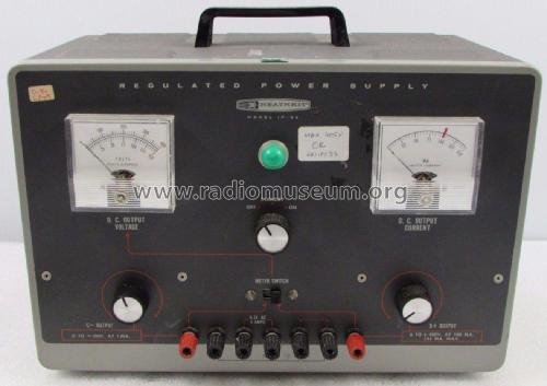
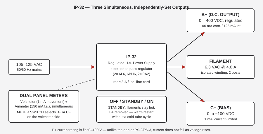
The Heathkit IP-32 is a regulated, tube-circuit, high-voltage bench power supply — Heath’s “Regulated H.V. Power Supply,” model IP-32. It is not a signal source, not a meter, not a tester of anything; it is the un-glamorous piece of gear that makes every other piece of tube-circuit bench work possible. It delivers, simultaneously and independently, the three rails a vacuum-tube circuit needs to come alive:
Table 1 — circuit needs to come alive
| Output | Rating | Purpose |
|---|---|---|
| B+ (plate/screen supply) | 0–400 VDC, regulated, continuously variable | Plate and screen voltage for the stage under test |
| Filament | 6.3 VAC @ 4.0 A (two binding posts) | Heater power for the tube(s) |
| Negative bias (C−) | 0 to −100 VDC @ 1 mA, variable | Grid bias, set independently of B+ |
That is the entire pitch, and it is a good one. Breadboard a preamp stage, an output stage, an oscillator, an RF amplifier — anything built around one or two tubes — and instead of first winding a power transformer, building a rectifier/filter, and bolting together a bias supply, you clip leads to seven front-panel binding posts and the circuit has everything it needs to run. The IP-32 is the power-supply section of whatever you are building, on loan.
⚠ Danger — this is lethal HV gear. The raw B+ rail inside the IP-32 sits at roughly 600 V DC before regulation, and the front panel delivers up to 400 V DC at up to 125 mA — comfortably in the range that stops a heart. The bleeder resistors draw only a few milliamps, so the internal filter capacitors hold a lethal charge for a long time after the supply is switched off and unplugged. Treat every internal node as live until you have personally discharged it. See Vol 4 for the full operating-safety procedure and the shared HV/mains discipline doc.
1.2 Why it earns bench space
A tube circuit needs three things a solid-state circuit does not: several hundred volts of plate supply, a separate low-voltage AC filament supply, and — for anything beyond the crudest fixed-bias design — a negative grid-bias rail. Building all three from scratch for every experimental circuit is a tax on curiosity: half a breadboarding session disappears into winding calculations, rectifier selection, and filter design before a single tube has been tested. The IP-32 collapses that tax to zero. Plug it in, dial up 250 V B+ and −8 V bias, hook the filament posts to the tube’s heater pins, and the only remaining engineering is the circuit you actually wanted to build.
This is precisely the role a regulated bench supply plays for solid-state work — except the tube world’s voltages are an order of magnitude higher and the failure modes are correspondingly more dangerous, which is why Heath built an entire regulated instrument around the job rather than leaving it to a raw transformer-rectifier-choke stack.
1.2.1 The three outputs in practice
B+. The plate/screen rail, 0–400 VDC, is the headline number, and it is genuinely regulated — not just filtered. Heath’s own performance figures (Vol 3 covers the regulator circuit in depth) claim ±1 % load regulation from no-load to full-load across the whole 100–400 V range, ±½ V for a 10 V line change, and less than 10 mV of ripple/jitter/noise. Critically, the IP-32’s B+ current rating is flat across the entire 0–400 V range — 100 mA continuous (125 mA intermittent) whether the dial reads 50 V or 400 V. That was a real advance over Heath’s earlier PS-2/PS-3 lab supplies, where available current fell as the voltage setting rose; the PS-4/IP-32 generation fixed that with a redesigned tube lineup and separate filament/power transformers (see §3 below).
Filament. A single isolated 6.3 VAC @ 4.0 A winding feeds two dedicated binding posts — enough for a 6L6-class output tube’s heater, several small-signal tubes in series-string, or a handful of low-current heaters in parallel. It is electrically isolated from the B+ and bias circuitry — the filament output rides its own winding on the multi-winding heater transformer, shared only with the pilot lamp (Vol 3 covers the transformer’s four windings in detail, including how the internal tube-heater windings are each individually bonded to their own tube’s cathode, since those cathodes float at high potential).
Bias (C−). 0 to −100 VDC, adjustable independently of B+, at up to 1 mA. This is enough current to bias a grid — a genuine load, not a leakage path — but it is deliberately small: unlike B+, the bias output is internally current-limited by design, which is also why there is no bias current meter on the front panel (there is not enough current flowing to be worth metering, and the limiting keeps it that way even into a fault).
1.2.2 Dual metering
Two analog panel meters read simultaneously: a 1 mA voltmeter movement and a 150 mA-full-scale ammeter, the latter permanently wired into the B+ line so you always know how hard the circuit under test is pulling. A front-panel METER SWITCH re-tasks the voltmeter side between two ranges/polarities — 0 to +400 V (reading B+) or 0 to −150 V (reading the bias rail) — via a pair of precision multiplier resistors, so one meter movement does double duty rather than cluttering the panel with a fourth dial. You dial in a plate voltage, glance at the current meter to confirm the stage is drawing what you expect, flip the meter switch to check bias, and you have a complete operating picture of the circuit under test without touching a separate multimeter.
1.2.3 STANDBY
The front-panel power switch is a three-position rotary: OFF / STANDBY / ON. STANDBY is the detail that separates a purpose-built tube supply from a bench transformer with a switch bolted on: it leaves the filament supply energized while removing B+ entirely. That matters for two reasons. First, tube cathodes should be allowed to reach operating temperature before plate voltage is applied — slamming B+ onto a cold cathode is harder on the tube and, in some designs, on the circuit. Second, STANDBY gives you a fast, repeatable way to kill plate voltage the instant something looks wrong on the bench — smoke, an unexpected meter swing, a burning smell — without waiting through a full cold-start warm-up cycle to get back to work once the fault is cleared. Every serious tube bench supply has some version of this feature; the IP-32’s rotary switch makes it a single twist of the wrist.
1.3 The lineage: one circuit, twenty years
The IP-32 is not a standalone design. It is one generation of a single Heath circuit that Heath sold, under five different model numbers, across roughly twenty years:
PS-4 (1957–62) → IP-32 (1962–67) → IP-17 (1967/68–77) → IP-2717 (1977–82) → IP-2717A / SP-2717A (1982, Heath-Zenith era).
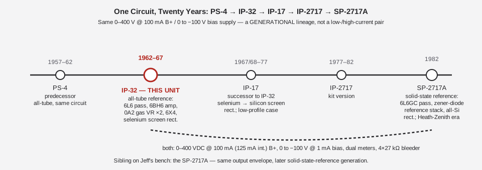
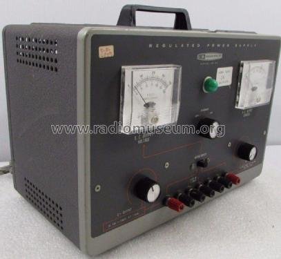
Every generation in that chain delivers the same fundamental output envelope: 0–400 VDC B+ @ 100 mA continuous (125 mA intermittent), 0 to −100 V bias @ 1 mA, dual meters, and a four-resistor bleeder network holding a minimum load on the pass elements. The IP-32 is, by Heath’s own numbers, electrically identical to its immediate predecessor the PS-4 — the two differ only in cosmetic styling (the IP-32 wears Heath’s darker “Classic II” panel treatment: dark gray face, silver nomenclature, black knobs).
1.3.1 IP-32 vs. its own successors — what actually changed
What did change, generation to generation, is how the regulator implements that same 0–400 V/100 mA job — and that is the load-bearing fact for anyone comparing an IP-32 to its later cousin the SP-2717A:
Table 2 — SP-2717A
| Generation | Years | Regulator reference | Series-pass tubes | Rectification |
|---|---|---|---|---|
| PS-4 | 1957–62 | tube (predecessor circuit) | tube | selenium/tube mix |
| IP-32 | 1962–67 | two 0A2 gas-regulator tubes | two 6L6 | silicon B+ doubler + selenium screen rect. + 6X4 tube bias rect. |
| IP-17 | 1967/68–77 | two 0A2 tubes | two 6L6 | selenium → silicon screen rectifiers; low-profile case |
| IP-2717 | 1977–82 | (kit version of IP-2717A circuit) | two 6L6GC | — |
| SP-2717A | 1982 | zener-diode reference stack | two 6L6GC | all-silicon |
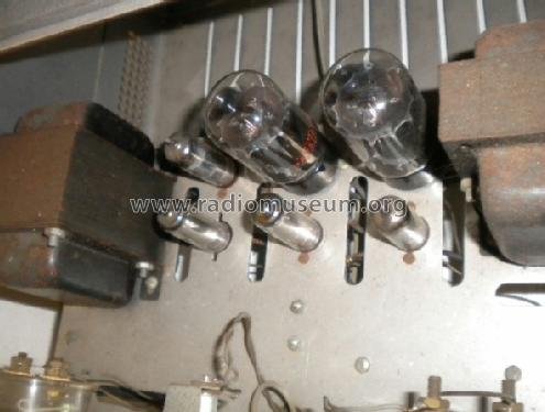
The IP-32 is the all-tube-reference generation: every active device that sets and holds the output voltage — the two 6L6 series-pass tubes, the 6BH6 control/error amplifier, the two 0A2 gas-discharge voltage-reference tubes, and the 6X4 bias rectifier tube — is a vacuum tube. The only solid-state parts in the whole regulation path are the silicon diodes in the B+ voltage doubler and the two selenium rectifiers feeding the screen supply, and neither of those does any regulating — they just rectify AC to DC. Vol 2 walks through exactly how that all-tube loop holds the output line flat; Vol 3 catalogs every device on the chassis.
Two decades later, the SP-2717A generation replaced the 0A2 gas-tube reference with a zener-diode reference stack, going all-silicon everywhere except the series-pass element itself — but the series-pass job, the actual heavy lifting of dropping raw B+ down to the set output voltage, stayed a pair of 6L6-family tubes across the entire lineage. Even the “solid-state-reference” generation never went solid-state on the pass element.
A framing correction worth stating plainly: it is tempting, looking at an “IP-32” and a later-model “SP-2717A” side by side, to assume the newer one is the beefier one — a low-current unit paired with a high-current unit. That is not what the published specifications say. Both units are rated 0–400 VDC @ 100 mA continuous / 125 mA intermittent on B+, and both are rated 0 to −100 V @ 1 mA on bias. If Jeff runs the pair as a “small jobs / big jobs” combination on the bench, that is a bench convention — perhaps driven by which unit is warmed up, or a preference for the SP-2717A’s optional 12.6 VAC @ 2 A heater winding — not a difference in B+ current capability. Vol 6 works through the full generational comparison; treat any claim that one unit “delivers more current” than the other as unsupported until measured.
1.3.2 What the later generations actually changed
Worth spelling out, since it is easy to conflate “later” with “more capable”: the IP-17 that replaced the IP-32 around 1967/68 kept the identical tube-regulated topology — same two 6L6 pass tubes, same 6BH6 control amp, same pair of 0A2 reference tubes — and made a handful of practical refinements: the selenium screen rectifiers (a known wear item, discussed in Vol 5) were swapped for silicon; the cabinet moved to a lower-profile case (13⅜ × 11¼ × 5½ in); a heater option added a 6.3-or-12.6 VAC selectable filament winding; the power switch gained a 120/240 V primary selection and a proper 3-wire grounded plug; and the meter switch gained a third pole plus two neon B+/C− indicator lamps. None of those changes touch the B+ or bias output ratings — the IP-17 is, in every number that matters to a circuit under test, the same supply as the IP-32 in a nicer box. The bigger architectural change — gas-tube reference to zener-stack reference, selenium and 6X4 rectification to all-silicon — arrives only at the IP-2717A / SP-2717A generation, some twenty years after the PS-4 started the lineage.
1.3.3 The name, precisely
This unit is correctly the Heathkit IP-32 — Heath’s “IP-” prefix denotes its instrument-power- supply series. The sibling covered in the companion dive is the SP-2717A — not a typo, and not an inconsistent prefix: “SP-2717A” is the Heath-Zenith-era relabel of the very same later- generation circuit cataloged elsewhere as the IP-2717A. SP-2717A and IP-2717A denote the same unit, not an assembled-vs-kit pair — Heath’s documented factory-wired designator for this family was instead IPW (the IP-17 had a wired counterpart, the IPW-17), so “SP” is not the marker of a factory-assembled version here.
1.4 Why regulated, specifically
A tube circuit’s plate supply does not strictly need to be regulated to work at all — a raw transformer-rectifier-capacitor stack will make a tube conduct. But an unregulated supply’s output sags under load and rises under no load, and it tracks every wiggle in the AC line. For a bench instrument meant to serve as the temporary power section of whatever circuit you’re currently building, that is a serious liability: the B+ voltage you dial in to bias a stage into its linear region will drift as soon as the stage starts drawing current, and again as soon as line voltage sags because someone turned on a shop vacuum on the same circuit. You end up chasing a moving target instead of characterizing your circuit.
Heath’s own figures for the IP-32 — ±1 % load regulation, ±½ V per 10 V line change, sub-10 mV ripple — mean the number on the meter is close to the number actually appearing at the tube’s plate, regardless of whether the stage under test is idling or pulling near its rated 100 mA, and regardless of whether the wall outlet is sagging on a hot afternoon. That predictability is what turns the IP-32 from “a transformer with a dial” into a genuine laboratory instrument — the same justification that puts a regulated bench supply, rather than a wall-wart, on any modern solid-state bench.
The regulation is also what makes the current meter meaningful as a diagnostic. Because the B+ line holds its set voltage independent of load (up to the 100/125 mA limit), a current reading that climbs unexpectedly while the voltage knob hasn’t moved is a real signal about the circuit under test — a shorting capacitor, a gassy tube, a wiring fault — rather than an ambiguous symptom that could equally be explained by the supply itself sagging. Vol 2 explains the regulator topology that delivers this; the point here is simply that “regulated” is not marketing language on this instrument — it is the entire reason to reach for the IP-32 instead of a bare transformer.
1.5 A concrete bench scenario
Concretely: say the project on the bench is a single-stage 6V6 audio output amplifier — a common first build for anyone learning tube-circuit design. Without a dedicated HV supply, that project starts with a power transformer selection (does it have a high-voltage secondary at all, and at what current?), a rectifier and filter design, and a separate bias arrangement, before a single volt of signal has been amplified. With the IP-32 on the bench:
- Filament posts go to the 6V6’s pins 2 and 7 (or the appropriate heater pins for the socket in use) — 6.3 VAC is already the correct heater voltage for the overwhelming majority of receiving tubes, the 6V6 included.
- B+ OUTPUT is dialed to the stage’s design plate voltage — commonly somewhere in the 250–350 V range for a 6V6 single-ended stage — and clipped to the plate circuit through the output transformer primary.
- C− OUTPUT is dialed to the design grid-bias voltage (a few volts negative, depending on the operating point chosen) and returned to the grid-bias network.
- The power switch goes to STANDBY first, letting the tube’s cathode reach operating temperature; then to ON, bringing up B+ under close watch of the current meter.
The entire power-supply engineering problem for that stage — three separate design tasks in a from-scratch build — collapses to turning three knobs and reading two meters. That collapsing of setup time, repeated across every tube-circuit experiment on the bench, is the entire case for owning an instrument like the IP-32 rather than building a fresh supply per project.
1.6 The kit-build angle
Like nearly everything Heath sold under the “Heathkit” banner, the IP-32 was sold as an assemble-it-yourself kit, not a finished instrument — part number, resistor, capacitor, tube socket, and a spiral-bound manual walking the builder through every solder joint. Bob Eckweiler (AF6C), whose “Heathkit of the Month” article on the IP-32 is written directly from the manual and schematic, recalls his university physics department buying IP-32 kits for exactly this kind of bench-supply role and assigning students to build them — and rated the build itself “not at all challenging,” consistent with Heath’s reputation for kits accessible to a first-time builder.
A factory-assembled (“wired”) version of the IP-32 specifically has not turned up in the sources behind this dive; Heath did sell wired versions of some instruments in this family at a premium over kit price (the IP-32’s electrical twin, the PS-4, listed at $56.95 kit versus $82.50 wired in Heath’s 1961 catalog), and the later IP-17 had a documented wired counterpart, the IPW-17. Whether Heath offered an equivalent “IPW-32” is not established here — treat the IP-32 as a kit-only offering unless a specific catalog listing turns up.
1.7 The dual-meter panel in more detail
It is worth dwelling a moment longer on how the metering earns its keep, because it is the main thing separating “a supply with two knobs” from “an instrument you can trust.” The current meter — 150 mA full scale, roughly 0.66 Ω of series/shunt resistance — sits permanently in the B+ line, so B+ current is always visible with no switching required; there is no equivalent meter on the bias line because the bias output’s internal current limiting keeps that current small enough (1 mA rated) that a meter would add little diagnostic value.
The voltmeter side is where the METER SWITCH does its work. A single 1 mA meter movement is shared between two ranges via a DPDT slide switch that swaps in a different precision multiplier resistor and reverses polarity: a 400 kΩ (1 %) multiplier gives 0 to +400 V for reading B+, and a 150 kΩ (1 %) multiplier gives 0 to −150 V for reading the bias line. That is a deliberately economical design choice — one meter movement and one switch buy the function of two separate meters — and it is also a maintenance point worth knowing about going into Vol 5: because the meter reading depends on both the mechanical zero of the movement and the precision of those multiplier resistors, a meter that has drifted with age can read convincingly wrong (a documented restoration found a unit reading 380 V on the panel against a true 400 V output — about 5 % low) while looking perfectly normal. Never trust the panel meter blind on a unit that hasn’t been checked against a calibrated DVM recently — dial by the meter for convenience, but verify the number that actually matters against external instrumentation.
1.8 Headline specifications
Table 3 — Headline specifications
| Parameter | IP-32 rating | Notes |
|---|---|---|
| B+ output | 0–400 VDC, regulated, continuously variable | flat 100 mA across the whole range |
| B+ current | 100 mA continuous / 125 mA intermittent | no active current limit — see Vol 2 §4 |
| Filament output | 6.3 VAC @ 4.0 A | two isolated binding posts |
| Bias (C−) output | 0 to −100 VDC @ 1 mA, variable | internally current-limited |
| Load regulation | ±1 % no-load to full-load, 100–400 VDC | |
| Line regulation | ±½ V output change per 10 V line change | |
| Ripple / jitter / noise | < 10 mV | |
| Output impedance | < 10 Ω, 1 Hz–1 MHz | |
| Meters | dual — 1 mA voltmeter movement + 150 mA-f.s. ammeter | METER SWITCH selects B+/bias on the voltmeter |
| Power switch | rotary OFF / STANDBY / ON | STANDBY: filaments live, B+ off |
| AC input | 105–125 VAC, 50/60 Hz | rear 3 A fuse |
| Dimensions | 13 in W × 8½ in H × 7 in D | 12 lb (16 lb shipping) |
| Production | 1962–1967 | kit, ≈ $56.95 |
Raw internal B+ (before the output pot) runs roughly 600 VDC — see the Danger callout above and Vol 4’s full safety procedure before opening the case.
1.9 Where it sits among Heath’s instrument line
Heath built regulated HV bench supplies across most of the company’s active decades because the market for them never went away: tube circuits remained the working substrate for audio, instrumentation, and RF design well past the point solid-state devices had taken over low-voltage signal work, and every tube circuit still needed the same three rails. The PS-1/PS-2/ PS-3 generation that preceded the PS-4/IP-32 lineage covered in this dive suffered from the current-droops-with-voltage limitation already mentioned; the PS-4/IP-32 generation is the point at which Heath settled on the architecture — separate filament and power transformers, a proper regulated series-pass loop, flat current across the voltage range — that would carry, essentially unchanged in its fundamentals, through five model numbers and two decades. That kind of multi-generation stability is itself a signal: it means the underlying circuit topology solved the bench-supply problem well enough on the first serious attempt that later revisions were refinements (better rectifiers, a nicer case, a solid-state reference) rather than redesigns. An engineer picking up either end of that twenty-year chain today — the tube-referenced IP-32 or the zener-referenced SP-2717A — is using essentially the same instrument Heath’s customers relied on from the Kennedy administration through the early Reagan years.
1.10 Reading this dive
This is Vol 1 of a six-volume series on the IP-32. If you want the why, you’re already reading it. For everything else:
- Vol 2 — How It Regulates. The series-pass regulator loop in detail: how two 6L6 tubes, a 6BH6 control amplifier, and a pair of 0A2 gas-reference tubes hold the B+ line to ±1 % — and why there is no active current limiting on B+.
- Vol 3 — Inside This Unit. Every device on the chassis: the B+ voltage-doubler rectifier, the selenium screen rectifiers, the 6X4 bias rectifier, the four-winding heater transformer, the bleeder network, and the metering circuit, wired up.
- Vol 4 — Using It. Operating procedure end to end — power-up sequence, STANDBY use, setting B+ and bias, reading the meters — and the full HV safety discipline for working on or around this unit.
- Vol 5 — Calibration & Refurbishing. Recap values, the classic leaky-coupling-cap fault, 6L6 vs. 6L6GC dissipation, selenium-rectifier replacement, and the zero/400 V adjustment procedure.
- Vol 6 — Cheatsheet & the Generational Pair. Quick-reference tables plus the full IP-32 ↔ SP-2717A comparison — what’s genuinely different between the two generations and what is not.
Sources
- Heathkit IP-32 assembly & operation manual (scans): archive.org (https://archive.org/details/Heathkit_IP-32_HV_Power_Supply), vintage-radio.info (https://www.vintage-radio.info/download.php?id=212), elektrotanya (https://elektrotanya.com/heathkit_ip-32_regulated_power_supply.pdf/download.html)
- Bob Eckweiler (AF6C), “Heathkit of the Month #67 — IP-32 Bench HV Power Supply,” OCARC RF newsletter, Aug 2015 — https://www.w6ze.org/Heathkit/Heathkit_067_IP32.pdf
- radiomuseum.org, Heath IP-32 — https://www.radiomuseum.org/r/heath_regulated_power_supply_ip_5.html
- radiomuseum.org, Heath IP-2717A — https://www.radiomuseum.org/r/heath_regulated_hv_power_supply_ip_2717a.html
- Chuck Penson, Heathkit Test Equipment Products (styling/production-date reference, cited by Eckweiler)