Heathkit IP-32 HV Power Supply · Volume 3
Heathkit IP-32 — Vol 3: Inside This Unit — Hardware, Devices, Outputs & Metering
Two 6L6 pass tubes, a 6BH6 error amp, and a pair of glowing 0A2 regulator tubes, all bolted into a 13-inch chassis a physics undergrad could kit-build in an evening.
3.1 Why this volume exists
Vol 1 placed the IP-32 in its lineage and Vol 2 walked the closed regulation loop as a system. This volume is the parts list and the panel layout — every active device, every output post, every transformer winding, every meter and knob, laid out so that a service session or a breadboard hookup can be planned without cracking the manual first. Treat the table in §2 as the canonical device complement for this instrument; every other volume in this dive defers to it.
The organization here follows the signal roughly front-to-back and top-to-bottom: what tubes and rectifiers are doing the work (§2), what the supply hands you on the binding posts (§3), where the power actually comes from (§4), how you read what it’s doing (§5), what you turn to change it (§6), and what’s protecting it at the mains (§7). Vol 2 already walked the feedback loop in detail — this volume assumes that background and instead answers “what is this specific part, and what does it physically do.”
⚠ Danger — Everything in this volume sits behind a chassis that, once the line cord is plugged in, has lethal voltage present at multiple internal nodes — including nodes that stay charged for minutes after the switch goes to OFF. Read Vol 3 §5 and the shared Bench Safety, Legal & Ethics doc before opening the case. Vol 4 covers full operating procedure; this volume only orients you to what’s inside.
3.2 The kit-build angle
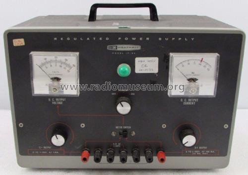
The IP-32 was sold as a Heathkit kit — a box of parts, a chassis, a punched panel, and a step-by-step instruction manual, assembled by the owner with a soldering iron and a few evenings of patience. Bob Eckweiler (AF6C), writing from direct experience, recalls his university physics department buying IP-32 kits by the case and handing them to students as an assembly exercise — and rates it an easy build, “not at all challenging.” That is a meaningful data point: this is not a finicky, marginal design. The circuit tolerates ordinary kit-building variance (lead dress, solder joint quality, part substitution within tolerance) and still regulates to spec.
A factory-assembled (“wired”) version of the IP-32 itself is not documented in the sources reviewed for this dive — the sibling IP-17 had a wired IPW-17 variant, and it’s plausible the IP-32 line did too, but no such catalog entry turned up. Every one of these units on the used market is overwhelmingly likely to be someone’s — or some department’s — kit build, which is part of why condition and workmanship vary unit to unit far more than with, say, a Tektronix scope off the same factory line.
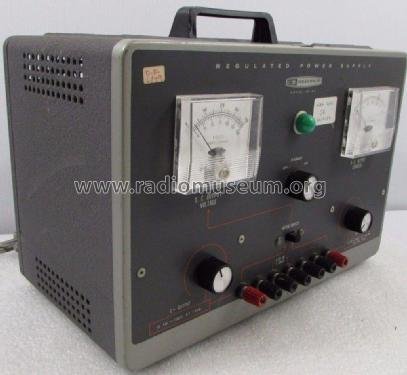
Pricing tracked the electrically identical PS-4 it replaced: kit price roughly $56.95, against a $82.50 factory-wired figure for the PS-4’s own wired option in the same era’s catalog. An exact year-by-year IP-32 catalog line wasn’t located for this dive, but the PS-4/IP-32 pairing being electrically identical circuits in different cabinetry (Chuck Penson’s “Classic II” styling — dark gray panel, silver nomenclature, black knobs, on the IP-32) means the pricing almost certainly tracked closely across the changeover. For a mid-1960s hobbyist or university lab, that kit price bought a regulated 400 V bench supply for well under half of what an equivalent factory-built instrument from a commercial test-equipment house would have cost — which is exactly the value proposition that made Heathkit’s instrument line (the “IP-” prefix, Heath’s instrument-power-supply series) a fixture on tube-era hobby and lab benches for two decades.
The build itself followed Heathkit’s signature format: a punched and silk-screened chassis and panel, every part bagged and numbered against a step-by-step manual, and a pictorial wiring diagram for anyone not yet comfortable reading a full schematic. Point-to-point wiring, not a printed circuit board — terminal strips and tube socket lugs are the “traces.” That construction style is part of why a fifty-to-sixty-year-old kit-built IP-32 is so serviceable today: every joint is inspectable and resolderable by eye, with no multilayer board to route around.
When buying or inheriting a used IP-32, the kit-build angle is worth inspecting for directly: non-factory solder joints (cold, grainy, or excessively globbed), non-stock wire colors or gauges from a prior repair, salvaged or substituted parts that don’t match the manual’s parts list, and evidence of a prior owner’s own troubleshooting (marker notes on the chassis, jumpered components, added terminal strips) are all common on kit-built gear of this vintage and don’t necessarily indicate a problem — but they do mean the schematic in the manual is a starting reference, not a guarantee of what’s actually inside any specific unit.
Cross-ref: Vol 5 (Calibration & Refurbishing) covers what fifty-plus years of kit-build variance and component aging typically does to one of these — leaky coupling caps, drifted trimmers, tired electrolytics.
3.2.1 Physical construction & styling
The IP-32 wears Chuck Penson’s “Classic II” Heathkit instrument styling: a dark gray front panel with silver-printed nomenclature, black knobs on every control, set into a steel chassis and case of the standard Heathkit instrument-line dimensions (13 in W × 8½ in H × 7 in D — see §7). That styling generation is a useful dating cue on its own for anyone trying to place an unlabeled or partially legible unit — it’s shared across a run of contemporary Heathkit test instruments from the same era, not unique to the IP-32, but distinct from the low-profile cabinet and different control layout the later IP-17 adopted (Vol 6 covers the full lineage). Being electrically identical to the earlier PS-4 underneath a new panel and case is, in fact, exactly what makes the IP-32 a distinct catalog entry from the PS-4 rather than a running spec change within it: this generation’s contribution was packaging, not circuit revision.
3.3 The active-device complement
This is the heart of the “what’s inside” question. Six vacuum tubes, six silicon diodes, and two selenium rectifiers regulate and rectify this supply — there are no transistors anywhere in the IP-32. That single fact is the throughline of the whole hardware story: every stage that does real work (series-pass regulation, error sensing, voltage reference, bias rectification) is a tube; only the B+ rectifier itself went solid-state, and even that used discrete silicon diodes, not an IC.
3.3.1 Full device table
Table 1 — Full device table
| Device | Qty | Role | Key ratings / notes |
|---|---|---|---|
| 6L6 | 2 | Series-pass regulator tubes, wired in parallel — act as variable resistors dropping raw B+ (≈600 V) down to the set output | Plates, cathodes, and heaters directly paralleled; screens fed from the separate ~230 V screen supply through 100 Ω suppression resistors each; control grids fed through 1 kΩ suppression resistors from the 6BH6 plate. Use 6L6GC (30 W plate dissipation) for full ratings — see §6. |
| 6BH6 | 1 | Control / error amplifier tube — compares sensed output against the reference and drives the paralleled 6L6 grids | Cathode tied to the regulated −150 V rail; plate feeds the 6L6 control grids through a 470 kΩ resistor; screen fed from a raw-B+-to−150 V divider so raw-supply sag is anticipated (this is what pins output impedance near zero — see Vol 2). |
| 0A2 | 2 | Gas voltage-reference / regulator tubes, 150 V each — develop the regulated −150 V and −300 V reference rails | Cold-cathode glow-discharge regulators; internal pin jumpers (anode pins 1 & 6; cathode pins 2, 4, 7) mean pulling either tube opens the rail rather than passing unregulated voltage — a built-in fail-safe. |
| 6X4 | 1 | Bias-supply rectifier tube — full-wave, dual-diode rectification of the negative bias winding | Rectifies the 600 V-CT winding to ≈380 V, which is then current-limited (R21) and regulated down to −150 V / −300 V by the two 0A2 tubes. |
| Silicon diodes | 6 total | 4 in the B+ voltage doubler (two series pairs); the doubler is the only place raw B+ is rectified — the remaining two of the sourced six-diode count aren’t located or explained in any source reviewed for this dive | Full-wave voltage-doubler topology on a 210 V transformer winding → ≈600 V no-load onto the 6L6 plates. This silicon B+ rectifier is the likely origin of any “solid-state” mislabel for the IP-32 — the rectification is silicon, the regulation is 100% tube. |
| Selenium rectifiers | 2 | Half-wave rectify the 175 V screen-supply winding, filtered to ≈230 VDC for the 6L6 screens | A known wear item on units this old — see §6 and Vol 5. Not to be confused with the B+ doubler diodes, which are also silicon but serve a different winding entirely. |
⚠ Danger — The 0A2 tubes glow visibly (a soft violet-pink discharge) when the unit is powered — that glow is your visual confirmation the reference chain is alive and the internal rails are at lethal potential, even with B+ output turned all the way down. Don’t take a dark 0A2 as proof the chassis is safe to open; check with a meter, not your eyes.
3.3.2 What’s conspicuously absent
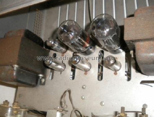
No transistors, no ICs, no op-amps anywhere in the signal path. That places the IP-32 firmly in the all-tube-reference generation of this design lineage — contrast with the Heathkit SP-2717A, which keeps the same 6L6-family series-pass element but replaces the 0A2 reference tubes with a stack of ten zener diodes and goes all-silicon on every rectifier. Vol 6 of this dive lays out the full generational comparison; the short version is that the IP-32 is the last generation of this circuit where you could point to every active device in the regulation path and it would be glass.
3.3.3 Device-by-device notes
The 6L6 pair. An octal-base beam-power tetrode, one of the most common power tubes ever made — the same family found in countless guitar and hi-fi audio power amplifiers. There’s no top-cap connection to route around; every element (heater, cathode, control grid, screen grid, beam plates, plate) lands on the octal base pins, which keeps the IP-32’s socket wiring simple. Wiring two of them directly in parallel — plates together, cathodes together, screens together, control grids together — doubles the effective current-handling and dissipation capacity of the series-pass element without changing anything about how the regulation loop drives it (Vol 2 treats the pair as a single composite pass device for exactly this reason).
The 6BH6. A 7-pin miniature-base sharp-cutoff pentode, originally intended for RF amplifier and oscillator duty in receivers — a slightly unusual choice for a DC error amplifier, but pentodes make fine DC amplifiers and the IP-32’s designers clearly had a bin of 6BH6es to draw from. It’s the smallest-signature tube on the chassis by heater draw (0.15 A) because it’s doing small-signal error sensing, not power work.
The 0A2 pair. Also a 7-pin miniature base, but electrically nothing like the 6BH6 or 6X4 sharing that base style — the 0A2 is a cold-cathode gas regulator tube, meaning it has no heater at all. That’s worth flagging explicitly: the filament-transformer winding table in §4 lists four windings covering the 6L6 pair, the 6X4, and the 6BH6 — the 0A2 tubes are absent from that table because they draw no heater current whatsoever. What powers the glow you see through the glass is the ionized gas fill conducting current between anode and cathode once the strike voltage across the tube is exceeded — the same basic mechanism as a neon lamp, scaled up and regulated for a stable ~150 V drop.
The 6X4. A 7-pin miniature dual-diode rectifier tube, commonly found doing B+ rectification duty in compact AC/DC table radios of the same era. Its job here is much lighter than typical — it’s only rectifying the bias-supply winding, not the whole B+ rail, which is why a single small rectifier tube suffices where the main B+ path needed a four-diode silicon doubler instead.
Silicon doubler diodes and selenium screen rectifiers. The four silicon diodes in the B+ doubler are unremarkable general-purpose rectifier diodes doing the highest-stress job on the chassis (blocking and passing the full raw B+ swing). The two selenium screen rectifiers are the one component class on this device list genuinely worth watching with age — selenium rectifiers are known to develop increased forward resistance and eventually fail as they age, and a failing selenium stack often announces itself with a distinctive acrid smell before it fails outright. See §2 note below and Vol 5 for the standard restoration answer (silicon-plus-series-resistor replacement).
3.3.4 Device identification quick-reference
Table 2 — Device identification quick-reference
| Device | Base / envelope | Heater? | How to spot it in the chassis |
|---|---|---|---|
| 6L6 (×2) | Octal base, glass (GT) or metal envelope depending on vintage/replacement | Yes — 6.3 V, 2.0 A combined | The two largest tubes on the chassis; no top-cap lead |
| 6BH6 | 7-pin miniature glass | Yes — 6.3 V, 0.15 A | Small glass envelope, sharp-cutoff pentode markings if legible |
| 0A2 (×2) | 7-pin miniature glass | No — cold-cathode, no heater winding | Visibly glows violet-pink when conducting; stone-cold to the touch relative to heated tubes nearby |
| 6X4 | 7-pin miniature glass | Yes — 6.3 V, 0.6 A | Smallest heated tube besides the 6BH6; dual-diode rectifier markings |
| Silicon doubler diodes (×4) | Discrete axial-lead diodes, not tube envelopes | — | Mounted near the 210 V winding leads, typically on a terminal strip rather than a socket |
| Selenium rectifiers (×2) | Stacked-plate selenium rectifier assemblies, not tube envelopes | — | Distinctive finned/stacked-plate metal assemblies; check for a burnt or fishy odor as a wear indicator |
Modern availability, briefly (general tube-market knowledge, not manual-sourced — verify current stock before planning a repair around it): 6L6GC is still in active production today for the guitar-amplifier market (several current manufacturers make reissue 6L6GC-family tubes), making it by far the easiest device on this list to source new. 6BH6 and 0A2 are essentially NOS-only at this point — no current production is known — though Cold-War-era surplus stock of both is not especially scarce on the vintage-tube market as of this writing. 6X4 sits in between: not in current production but common enough as a shared type across decades of AC/DC radio production that NOS and pulled examples turn up regularly. Silicon diodes and selenium-replacement silicon-plus-resistor kits are, naturally, trivial to source new from any electronics distributor.
3.3.5 A caution on look-alike tube types
Several devices on this chassis share a base style or a general silhouette with other, electrically different tube types from the same manufacturing era — worth a moment’s caution before pulling a tube based on appearance alone. The 0A2 belongs to a small family of similarly-numbered cold-cathode voltage regulators (0A2/0B2/0C3/0D3-style designations across manufacturers) with different regulated voltages baked into the gas fill and electrode spacing — swapping in a look-alike from that family without checking the actual type number would quietly shift the IP-32’s internal reference voltages and, with them, its calibration. Likewise, the 6L6 family has close octal-base relatives (6V6, 5881, KT66, and others) that are physically similar enough at a glance to be mixed up in a parts bin but are not interchangeable substitutes for this circuit’s rated dissipation and characteristics without re-verifying the fit. When in doubt, read the printed type number on the glass — don’t identify a tube by socket location and silhouette alone.
3.4 Hardware, side by side: IP-32 vs. the SP-2717A
The Heathkit SP-2717A sitting next to this unit on Jeff’s bench is not a different-capacity supply — it’s the same B+/bias/filament output envelope built twenty years later with a different active-device complement. Vol 6 of this dive carries the full generational analysis (all five generations, PS-4 through SP-2717A); the table below is the hardware-level snapshot relevant to this volume.
Table 3 — Hardware, side by side: IP-32 vs. the SP-2717A
| Aspect | IP-32 (this unit) | SP-2717A (sibling) |
|---|---|---|
| Era | 1962–1967 | 1982, Heath-Zenith era |
| Series-pass tubes | 2× 6L6 (use 6L6GC for full rating) | 2× 6L6GC |
| Control / error amp | 6BH6 | 6AU6 |
| Voltage reference | 2× 0A2 gas-regulator tubes | Stack of ten zener diodes (ZD1–ZD10) |
| Bias rectifier | 6X4 tube | All-silicon — no 6X4 |
| Screen / auxiliary rectifiers | Silicon B+ doubler + 2 selenium screen rectifiers | All-silicon — no selenium anywhere |
| B+ output | 0–400 VDC, 100 mA continuous / 125 mA intermittent | Identical — 0–400 VDC, 100 mA continuous / 125 mA intermittent |
| Bias output | 0 to −100 VDC @ 1 mA | Identical — 0 to −100 VDC @ 1 mA |
| Filament | 6.3 VAC @ 4 A | 6.3 VAC @ 4 A (the lineage’s later IP-17/IP-2717 generations added an optional 12.6 VAC @ 2 A heater tap — confirm which winding option is present on any specific SP-2717A unit before assuming) |
| Metering / bleeder | Dual meters, METER SWITCH, 4×27 kΩ 2 W bleeder | Same scheme — dual meters, METER SWITCH, 4×27 kΩ 2 W bleeder |
| Build | Heathkit kit | Factory-assembled (“SP” ≈ the assembled, non-kit version of the identical IP-2717A) |
Note — the SP-2717A’s 6AU6 control/error-amp tube and its ten-zener reference stack (ZD1–ZD10) are drawn from the SP-2717A’s own manual and schematic (see that unit’s deep dive); this IP-32 volume names them only for the generational comparison.
The load-bearing point, worth restating because it contradicts an easy assumption: these two units are not a low-current/high-current pair. Both deliver the identical 0–400 V @ 100 mA (125 mA intermittent) B+ rating and the identical 0 to −100 V @ 1 mA bias rating. What changed across the twenty years between them is entirely how that rating gets delivered — tube reference versus solid-state reference, tube bias rectification versus all-silicon — not how much. If the two are run as a low-power/high-power pair on the bench, that’s a convention Jeff has adopted, not something either supply’s spec sheet supports on its own.
3.5 Outputs — exactly what this supply delivers
Three simultaneous, independently adjustable DC outputs, plus AC filament power, on seven front-panel binding posts.
Table 4 — Outputs — exactly what this supply delivers
| Output | Range | Current | Notes |
|---|---|---|---|
| B+ | 0–400 VDC, continuously variable | 100 mA continuous, 125 mA intermittent max | Full rated current is available across the entire 0–400 V range — current capability does not fall off as voltage rises, unlike the earlier PS-2/PS-3 designs. Regulated. |
| Bias (C−) | 0 to −100 VDC, continuously variable | 1 mA | Internally current-limited (R21 ahead of the 0A2 chain, plus the C− OUTPUT pot’s series resistor) — this is why there’s no bias current meter. |
| Filament | 6.3 VAC, fixed | 4.0 A | Two dedicated binding posts, isolated winding, unregulated AC — for powering the heaters of whatever tube circuit is under test. |
| Chassis GND | — | — | Bonding post, separate from the two COMMON posts. |
| COMMON ×2 | — | — | Return path for B+ and C− respectively (the supply’s internal reference points, not necessarily tied to chassis — see below). |
⚠ Danger — Raw B+ on the doubler capacitors runs to roughly 600 V — well above the 400 V maximum the front panel will ever show you. That 600 V node exists whether or not the B+ OUTPUT pot is turned down, any time the unit is in the ON position. Turning B+ OUTPUT to zero does not zero the internal raw supply.
3.5.1 Regulation performance (for reference — see Vol 2 for the mechanism)
Table 5 — Regulation performance (for reference — see Vol 2 for the mechanism)
| Parameter | Spec |
|---|---|
| Load regulation | ±1 %, no-load to full-load, over 100–400 VDC |
| Line regulation | ±½ V output change per 10 V line change |
| Ripple, jitter & noise | < 10 mV |
| Output impedance | < 10 Ω, 1 Hz–1 MHz |
In practical breadboard terms: a load regulation figure of ±1 % across the full 100–400 V range means a tube circuit that swings its own current draw as it operates (a class-AB output stage, for instance) won’t drag the supply’s B+ around enough to matter for most experiments; the sub-10 Ω output impedance through 1 MHz means the supply itself won’t be the dominant source of high-frequency noise coupling into a sensitive audio or RF circuit under test — the deliberately-near-zero output impedance discussed in Vol 2 is what buys that headroom.
3.5.2 Floating / insulated posts — what “floatable” means here
The B+, bias, and COMMON posts are not hard-bonded to chassis ground inside the supply — the chassis GND post is separate and distinct from the B+/C− COMMON posts. That matters for breadboarding tube circuits where the designer wants to choose their own ground reference (for example, referencing a cathode-bias point rather than tying straight to chassis) rather than being forced onto the supply’s internal ground scheme. It also means it’s entirely possible to wire the supply in a way that floats its output well above or below true earth potential — treat every post as potentially live relative to the bench, not just relative to each other, until you’ve traced the actual wiring on the unit in front of you.
⚠ Danger — Floatable does not mean isolated from mains hazard. A miswired floating reference can put lethal potential on a post you assumed was safe because “it’s not B+.” Verify with a meter before touching any post, every time.
3.5.3 Binding-post wiring cookbook
Seven posts, three functions. The pattern below is the general shape of how the IP-32’s outputs map onto a typical tube circuit under breadboard test — treat it as a starting layout, not a substitute for tracing the actual device-under-test’s own schematic and grounding scheme.
Table 6 — Binding-post wiring cookbook
| Breadboard task | B+ post | Bias (C−) post | Filament posts | COMMON / GND notes |
|---|---|---|---|---|
| Single-stage triode gain-stage test | Feeds the plate through a load resistor | Feeds a cathode-bias-free grid-leak bias point, or left unused if self-biasing with a cathode resistor | Power the tube’s heater directly | B+ COMMON ties to the stage’s ground/cathode return; chassis GND separately bonds the breadboard’s metal chassis if any |
| Push-pull output-stage bias test | Feeds both plates (or plate-to-plate via a load) | Feeds a shared fixed-bias grid supply for both output tubes | Powers both tubes’ heaters | Keep C− COMMON distinct from B+ COMMON if the bias return isn’t the same node as plate current return in the DUT |
| Voltage-reference / regulator experiment | Feeds the raw supply node under test | Unused, or used as an auxiliary low-current negative rail | Powers any heater in the experimental circuit | Chassis GND bonds the experimental board’s frame for shock safety, independent of the DC reference scheme |
Cross-ref: Vol 4 walks the full power-up sequence for hooking a breadboard tube circuit to these posts safely, including the STANDBY pre-warm step described in §4 below.
3.5.4 A note on leads and connectors for these posts
The binding posts themselves are ordinary insulated banana-jack-style posts, but what’s on the other end of the lead matters more here than on a typical low-voltage bench supply. HV-rated silicone or PVC test leads (rated well above the ≈600 V raw internal potential, not just the 400 V panel-visible maximum) are the right choice for anything touching the B+ post; bare alligator clips on thin hookup wire, common on a low-voltage breadboard, are a poor match for a rail that can bite. Banana plugs that fully shroud the metal tip are worth the small extra cost specifically for the B+ and C− leads — an exposed banana-plug tip at the free end of a lead still carrying full B+ potential (because the far end came unplugged from the breadboard mid-session, say) is exactly the kind of small lapse that turns into a serious injury with this class of supply.
3.6 Protection hardware — the minimum-load bleeder
Distinct from any active current-limit circuit (there isn’t one on B+ — see §7), the IP-32 carries a small piece of purely passive protection hardware worth calling out as physical parts on the chassis: a bleeder network of four 27 kΩ, 2 W resistors wired in series from the 6L6 cathodes down to the regulated −300 V rail. That string forces roughly 3 mA of minimum current draw even with B+ OUTPUT turned all the way down to 0 V and nothing connected to the output posts at all — without it, the series regulator would have no load to work against at very light output settings and could lose control of the loop entirely. It’s a deceptively simple piece of hardware doing a job that a purely active regulator design would otherwise need dedicated circuitry for.
Two more passive safeguards sit alongside the bleeder, both already touched on in §2’s device table:
- R21 current-limits the 6X4’s rectified output ahead of the 0A2 regulator chain, protecting the 0A2 tubes from an overcurrent surge before the reference chain ever sees it.
- The 0A2 internal pin jumpers (anode on pins 1 and 6, cathode on pins 2, 4, and 7) mean that physically pulling either 0A2 tube from its socket opens the rail rather than letting unregulated raw voltage flow through in its place — a fail-safe baked directly into the tube’s own pin assignment, not a separate protection component at all.
None of this is a substitute for active foldback current limiting on B+ itself, which the design simply doesn’t have (§7) — it’s protection against the regulator losing its footing at light loads and against a pulled reference tube passing raw voltage, not protection against a shorted output post.
3.7 The two transformers — why STANDBY keeps filaments hot
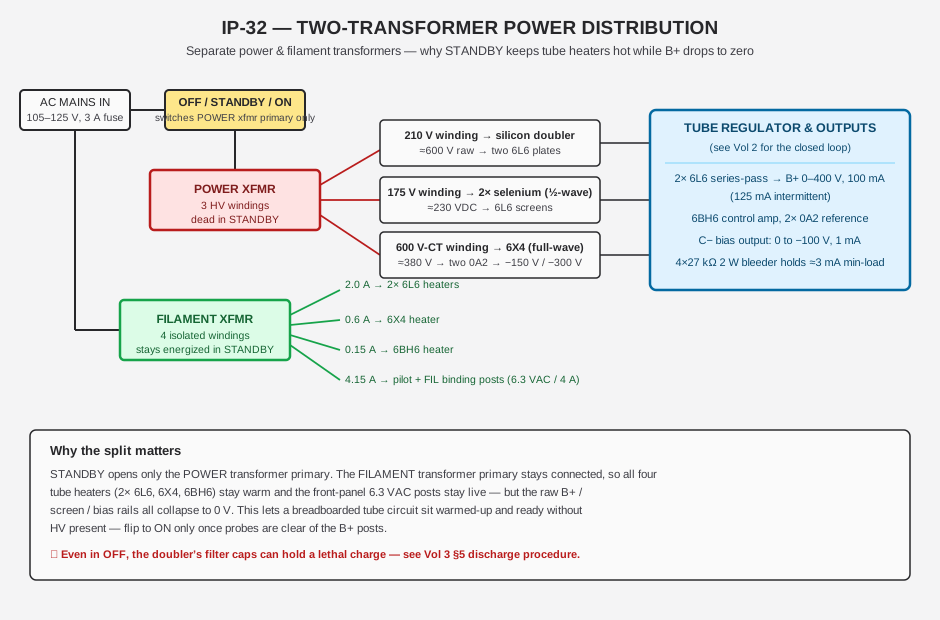
The IP-32 uses two separate transformers, not one transformer with multiple secondaries — a power transformer carrying the three high-voltage windings, and a dedicated filament transformer with four isolated low-voltage windings. This split is a deliberate design choice inherited from the PS-4 and it’s the reason the OFF/STANDBY/ON switch behaves the way it does.
3.7.1 Filament transformer — four isolated windings
Table 7 — Filament transformer — four isolated windings
| Winding | Current rating | Feeds |
|---|---|---|
| 6.3 V | 2.0 A | Both 6L6 heaters (paralleled) |
| 6.3 V | 0.6 A | 6X4 heater |
| 6.3 V | 0.15 A | 6BH6 heater |
| 6.3 V | 4.15 A | Pilot lamp + the two front-panel filament binding posts |
Each winding has one side bonded to its own tube’s cathode, because several of the cathodes in this circuit float at high DC potential relative to chassis — an ordinary shared heater winding would break down the heater-to-cathode insulation rating of the tube. Isolating each heater winding to its own tube’s cathode potential is what lets those tubes survive operating with hundreds of volts between heater and cathode.
3.7.2 Power transformer — three HV windings
Table 8 — Power transformer — three HV windings
| Winding | Feeds | Rectification | Approx. DC result |
|---|---|---|---|
| 210 V | B+ doubler | Full-wave voltage doubler, 4 silicon diodes | ≈600 V raw onto the 6L6 plates |
| 175 V | Screen supply | Half-wave, 2 selenium rectifiers in series | ≈230 VDC to the 6L6 screens |
| 600 V-CT | Bias/reference supply | Full-wave, 6X4 tube | ≈380 V, then current-limited and 0A2-regulated to −150 V / −300 V |
The manual’s own commentary — reported by AF6C — notes the power transformer is somewhat under-rated for sustained heavy duty. Don’t lean on this supply at max current for extended periods; the transformer, not the tubes, is the weak point, and transformers for a 60-year-old Heathkit design are hard to source if one cooks.
3.7.3 A back-of-envelope power budget
None of the sources reviewed for this dive publish a transformer VA rating directly, so the figures below are an illustrative bound derived from the confirmed raw-supply and output figures elsewhere in this dive — treat them as an engineering sanity check, not a specified rating.
The single most demanding condition for the pass-tube pair is a low output-voltage, high-current setting: raw B+ sits at roughly 600 V regardless of where B+ OUTPUT is set, so if the front panel is turned down toward 0 V while still drawing close to the 125 mA intermittent maximum, the entire 600 V drop is happening across the 6L6 pair rather than across the load. That works out to approximately 600 V × 0.125 A ≈ 75 W of instantaneous dissipation split across two tubes — call it roughly 37–38 W apiece in the worst case, briefly. That number is exactly why the facts in §6 flag metal/GA/GB-envelope 6L6 tubes (rated ~19 W plate dissipation) as a real over-dissipation risk at this corner of the operating envelope, and why even the 6L6GC’s 30 W rating leaves only modest headroom — the intermittent-only 125 mA rating (vs. the 100 mA continuous figure) exists precisely so this worst-case condition isn’t sustained.
At the opposite corner — full 400 V output at full continuous 100 mA — the load itself is absorbing 40 W (400 V × 0.1 A), and the pass-tube drop is comparatively small, so this end of the range is comfortable for the tubes but is where the transformer and rectifier stages see their heaviest sustained current draw. Between these two corners, the total power the supply’s internal wiring and transformers have to move is on the order of several tens of watts continuously, plus the filament transformer’s own roughly 43 W of heater load (summing the four winding current ratings from §4’s table at 6.3 V: 2.0 + 0.6 + 0.15 + 4.15 = 6.9 A, so 6.9 A × 6.3 V ≈ 43 W) — a modest total budget by modern switching-supply standards, but a meaningful one for a transformer this physically small (12 lb total unit weight, case included), which is consistent with the manual’s own “somewhat under-rated” caution.
Cross-ref: Vol 4 covers the operating implications of this split directly — using STANDBY to pre-warm a breadboarded tube circuit’s filaments before HV is ever applied is standard practice with this supply, and it’s the two-transformer architecture that makes it possible.
3.8 Metering — one voltmeter movement, two scales, plus an independent ammeter
Two panel meters, read together, monitor the supply continuously.
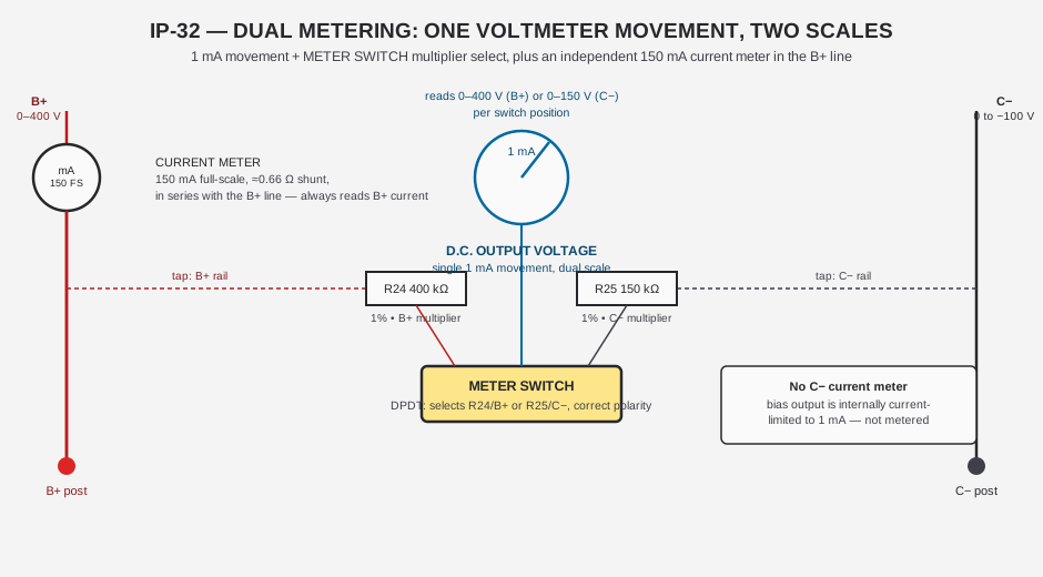
Table 9 — Metering — one voltmeter movement, two scales, plus an independent ammeter
| Meter | Movement | Range(s) | Mechanism |
|---|---|---|---|
| D.C. OUTPUT VOLTAGE | 1 mA | 0–400 V (B+) or 0–150 V (C−), switch-selected | METER SWITCH is a DPDT slide switch selecting series multiplier resistor and polarity: R24 = 400 kΩ, 1 % for the B+ scale, R25 = 150 kΩ, 1 % for the bias scale |
| D.C. OUTPUT CURRENT | Dedicated 150 mA movement | 0–150 mA full-scale | ≈0.66 Ω series/shunt resistance, permanently wired in the B+ line — reads B+ current only, regardless of METER SWITCH position |
There is no bias current meter. Bias current is small by design (1 mA rated) and internally current-limited, so a dedicated meter for it wasn’t worth the panel space or the cost in the original kit BOM.
3.8.1 Reading the meters in practice
Both panel meters are conventional D’Arsonval moving-coil movements — a pointer sweeping a printed scale, not a digital readout — which means reading them accurately takes a moment’s care: view the pointer straight-on (parallax will skew the apparent reading on an angled glance), let the pointer settle rather than reading it mid-swing after a control adjustment, and remember that the voltage scale printed on the dial only applies for whichever METER SWITCH position is currently selected — a dial calibrated in a 0–400 scale is being asked to also serve a 0–150 range in the other switch position, so the printed scale markings themselves are dual-purpose (some IP-32 dial faces print both scales side by side; others rely on the operator remembering which position is active).
Table 10 — Reading the meters in practice
| METER SWITCH position | What the voltmeter reads | What the ammeter reads | Typical use |
|---|---|---|---|
| B+ | 0–400 V (B+ rail) | 0–150 mA (always B+ current) | Normal operating monitoring — both meters relevant simultaneously |
| C− (bias) | 0–150 V scale, actual bias range 0 to −100 V | 0–150 mA (still B+ current — unrelated to the bias reading) | Setting/verifying bias voltage; note the ammeter is not telling you anything about bias current in this mode |
That second row is worth internalizing: switching METER SWITCH to the bias position changes what the voltmeter shows, but the current meter never stops reading B+ current — there is no position that shows bias current, because (as above) that output has no dedicated ammeter at all.
Cross-ref: Vol 5 covers the meter-calibration angle in detail — the panel movement is a mechanical analog meter and it drifts. One documented restoration read 380 V on the meter against a true 400 V output, roughly 5 % low; re-zero the pointer and verify R24/R25 are still within tolerance before trusting the panel reading for anything precision-dependent. For anything you actually care about, confirm against a DVM.
3.9 Controls
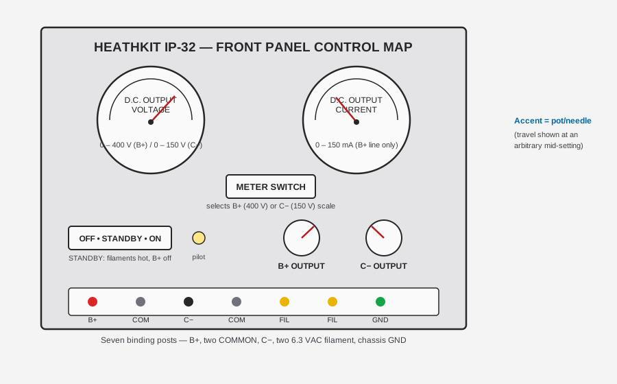
Table 11 — Controls
| Control | Type | Function |
|---|---|---|
| OFF / STANDBY / ON | 3-position rotary | OFF: no power anywhere. STANDBY: filament transformer primary energized (heaters warm, FIL posts live), power transformer primary open (all HV rails at 0 V). ON: both transformers energized, full operation. |
| B+ OUTPUT | Potentiometer | Sets the B+ voltage divider tap feeding the 6BH6 control grid — adjusts B+ output continuously from 0 to 400 V (see Vol 2 for the loop mechanism). |
| C− OUTPUT | Potentiometer | Sets bias output continuously from 0 to −100 V. |
| METER SWITCH | DPDT slide switch | Selects which rail (B+ or C−) the shared voltmeter movement reads, switching in the correct multiplier resistor and polarity simultaneously. |
| Pilot lamp | Indicator | Confirms the filament transformer primary is energized (lit in both STANDBY and ON) — it is not an HV-present indicator. |
The OFF/STANDBY/ON control is a rotary switch with three detented positions, wired so each position makes and breaks specific transformer-primary contacts as described in §4 — there’s no ambiguity about which position you’re in by feel alone, but always confirm visually before reaching toward the output posts. The two OUTPUT potentiometers set the internal divider taps that feed the regulation loop’s reference point (Vol 2 covers exactly how that tap translates to output voltage); expect typical carbon or wirewound pot construction of the era, meaning decades-old units may show scratchy or intermittent operation exactly like any old pot — a common, low-drama refurbishment item covered in Vol 5, not a sign of deeper regulator trouble by itself.
⚠ Danger — The pilot lamp tells you the unit has AC power, not that it’s safe. It’s lit in STANDBY, when B+ is nominally zero, and it’s lit in ON, when raw B+ is sitting at ~600 V inside the chassis. Never use the pilot lamp as your safety cue for whether HV is present — use a meter, and assume live until proven otherwise.
3.10 Mains input, fusing, and physical facts
Table 12 — Mains input, fusing, and physical facts
| Parameter | Value |
|---|---|
| AC input | 105–125 V, 50/60 Hz |
| Fuse | Rear-panel, 3 A |
| Cord strain relief | Heyco cord clamp |
| Dimensions | 13 in W × 8½ in H × 7 in D |
| Weight | 12 lb (16 lb shipping) |
A 3 A fuse on a 105–125 V line is rated to interrupt on the order of 315–375 VA of total mains draw before it opens — comfortably above the supply’s own internal power budget worked through in §4, which leaves headroom for whatever heater and B+ load a breadboarded circuit under test adds on top of the IP-32’s own consumption, up to the point where total draw actually approaches that fuse rating. This is the only line-level protection in the entire supply; there’s no soft-start, no inrush limiting beyond whatever the transformers’ own leakage inductance provides, and no resettable breaker — a blown fuse means physically replacing it before power returns.
Because the power and filament transformers switch independently (§4), the inrush picture at power-up is split in two: moving OFF → STANDBY draws whatever surge the filament transformer and four cold tube heaters pull as they first energize (a brief, modest spike typical of any small transformer with a resistive-ish heater load), while moving STANDBY → ON separately draws whatever surge the power transformer and the B+ doubler’s discharged filter capacitors pull as they first energize. Splitting the two draws across two separate switch actions, rather than hitting both transformers simultaneously from a cold start, is itself a mild kindness to the fuse and to the transformers’ own inrush tolerance — one more small benefit of the two-transformer architecture beyond the headline STANDBY behavior.
No electronic current-limit or foldback protects B+ beyond this 3 A mains fuse and the physical dissipation limit of the pass tubes themselves — a short on the B+ output is stopped by the fuse blowing or a 6L6 cooking, not by any active limiting circuit. This is a meaningful distinction from more modern regulated supplies, and it’s worth internalizing before treating this unit like a short-circuit-proof modern bench supply. The bias (C−) output is the sole exception — it is internally current-limited to its rated 1 mA by design, independent of the fuse.
⚠ Danger — Do not test this supply’s B+ output for “how much current can it really deliver” by shorting it and watching the meter. There is no active protection on that rail beyond a 3 A mains fuse and whatever the 6L6 pair can survive before letting go. Fuses are slow; tubes are not always slower.
3.11 Symptom-to-hardware quick map
Full repair procedure belongs in Vol 5 — this is only a hardware-literacy pointer, so a symptom noticed at the bench can be mapped to the physical part most likely responsible before opening the manual’s troubleshooting chart.
Table 13 — Symptom-to-hardware quick map
| Symptom | Most likely hardware area | Why |
|---|---|---|
| B+ won’t reach 400 V / zero-adjust misbehaves | The classic leaky ~0.047 µF coupling cap between the 6BH6 control grid and the 6L6 cathodes | A well-documented, specific known fault for this exact circuit (§2, Vol 5) |
| Regulation noticeably worse than ±1 % / set-point has drifted | 0A2 reference tubes aging | Gas regulator tubes drift their regulated voltage with hours of service |
| Screen supply low / 6L6 screens starved | Selenium screen rectifiers degrading | Known wear item — increasing forward resistance with age (§2) |
| Panel voltmeter reads noticeably off a DVM reference | Mechanical meter zero drift, or R24/R25 out of tolerance | Documented restoration case: 380 V shown vs. 400 V actual (§5) |
| Hum in a sensitive breadboarded circuit | AC lead routing near the power transformer, or a filter cap losing capacitance | Standard restorer’s fix: re-route AC leads (§5); recap if hum correlates with ripple rise |
| STANDBY position acts intermittent / filaments flicker | Oxidized switch contacts | Common age-related wear on a rotary switch this old |
| One or both 6L6 running visibly hot / early failure | Metal/GA/GB envelope in place of 6L6GC at a low-V/high-I setting | Matches the worst-case dissipation math in §4 |
| No output at all, pilot lamp lit | Check the rear 3 A fuse first, then trace forward from the transformer secondaries | No active fault-reporting exists beyond the fuse (§7) |
Cross-ref: Vol 5 (Calibration & Refurbishing) is the authoritative repair/restoration volume; treat this table as triage, not a repair procedure.
3.12 Quick reference — full spec & device complement
One consolidated table, pulling every figure from this volume together for a bench-side glance. Where a value is a design bound rather than a directly-published transformer/component spec, it’s marked “derived” per the worked reasoning in §4.
Table 14 — Quick reference — full spec & device complement
| Category | Item | Value / identity |
|---|---|---|
| Active devices | Series-pass tubes | 2× 6L6 (use 6L6GC for full-rating operation) |
| Control / error amp | 1× 6BH6 | |
| Voltage reference | 2× 0A2 (gas, cold-cathode, no heater) | |
| Bias rectifier | 1× 6X4 | |
| B+ doubler rectifiers | 4× silicon diodes | |
| Screen-supply rectifiers | 2× selenium (wear item) | |
| Transistors / ICs | None | |
| Outputs | B+ | 0–400 VDC, 100 mA continuous / 125 mA intermittent |
| Bias (C−) | 0 to −100 VDC @ 1 mA, internally current-limited | |
| Filament | 6.3 VAC @ 4.0 A, isolated winding | |
| Ground/common posts | 1× chassis GND, 2× COMMON (B+ and C− returns, floatable) | |
| Regulation | Load regulation | ±1 %, no-load to full-load, 100–400 VDC |
| Line regulation | ±½ V per 10 V line change | |
| Ripple/jitter/noise | < 10 mV | |
| Output impedance | < 10 Ω, 1 Hz–1 MHz | |
| Protection | B+ active current limit | None — mains fuse + pass-tube dissipation limit only |
| Bleeder | 4× 27 kΩ, 2 W in series, ≈3 mA min-load | |
| Bias-rail limiting | R21, ahead of the 0A2 chain | |
| 0A2 fail-safe | Internal pin jumpers open the rail if a tube is pulled | |
| Transformers | Power transformer | 3 HV windings — 210 V (doubler), 175 V (screen), 600 V-CT (bias) |
| Filament transformer | 4 isolated windings — 2.0 A / 0.6 A / 0.15 A / 4.15 A, all 6.3 V | |
| Raw B+ (no-load) | ≈600 V — lethal, present whenever the unit is ON | |
| Worst-case pass-tube dissipation | ≈75 W combined at low-V/high-I setting — derived | |
| Metering | Voltmeter movement | 1 mA, dual-scale via METER SWITCH (0–400 V B+ / 0–150 V C−) |
| B+ multiplier | R24, 400 kΩ, 1 % | |
| C− multiplier | R25, 150 kΩ, 1 % | |
| Ammeter | Dedicated 150 mA full-scale, ≈0.66 Ω, B+ line only | |
| Controls | Power switch | 3-position rotary: OFF / STANDBY / ON |
| Output pots | B+ OUTPUT, C− OUTPUT | |
| Meter select | METER SWITCH, DPDT slide | |
| Mains | Input | 105–125 V, 50/60 Hz |
| Fuse | 3 A, rear panel | |
| Strain relief | Heyco cord clamp | |
| Physical | Dimensions | 13 in W × 8½ in H × 7 in D |
| Weight | 12 lb (16 lb shipping) | |
| Build | Heathkit kit, ≈$56.95 (tracks the electrically identical PS-4’s kit price) | |
| Era | 1962–1967 |
Sources
- Heathkit IP-32 assembly & operation manual scans — archive.org
(
https://archive.org/details/Heathkit_IP-32_HV_Power_Supply), vintage-radio.info (https://www.vintage-radio.info/download.php?id=212), elektrotanya (https://elektrotanya.com/heathkit_ip-32_regulated_power_supply.pdf/download.html) - Bob Eckweiler (AF6C), “Heathkit of the Month #67 — IP-32 Bench HV Power Supply,” OCARC RF
newsletter, Aug 2015 —
https://www.w6ze.org/Heathkit/Heathkit_067_IP32.pdf - radiomuseum.org, Heath IP-32 Regulated Power Supply entry —
https://www.radiomuseum.org/r/heath_regulated_power_supply_ip_5.html - pudar.net, IP-32 restoration write-up —
https://pudar.net/heathkit-ip-32-restoration/ - Antique Radio Forums, IP-32 repair thread —
https://antiqueradios.com/forums/viewtopic.php?t=440 - Chuck Penson, Heathkit Test Equipment Products (styling names, production dates), as cited by AF6C