Heathkit IP-32 HV Power Supply · Volume 4
Heathkit IP-32 — Vol 4: Using It — Operating Procedure & HV Safety
A step-by-step bench procedure for a supply that can put 600 V across your hands before you've even touched the output posts.
4.1 Scope of This Volume
This is the operator’s volume: how to bring the IP-32 up safely, set its outputs, read its meters, wire a device under test (DUT) to its floating posts, and shut it back down without leaving anything charged. Vol 2 covers why the regulation loop behaves the way it does; Vol 3 covers what is physically inside the case; Vol 5 covers calibration and recap. This volume assumes the unit is in known-good electrical condition — if you inherited one that has sat in a basement for twenty years, read Vol 5’s Variac-and-bulb-limiter bring-up procedure first and do not follow the fast path below on a first power-up.
⚠ Danger — read this whole volume before you touch the power switch. The IP-32 is a lethal-voltage instrument. Raw B+ inside the case sits at roughly 600 V DC, the front-panel B+ output goes to 400 V DC, and there is a −300 V internal reference rail. None of these nodes are current-limited by anything except the mains fuse and the physical dissipation limit of the pass tubes. The bleeder network is a minimum-load bleeder, not a safety-discharge bleeder — it does not make the unit safe seconds after you switch it off. Section 10 of this volume and the hub-wide
_shared/legal_ethics.mdare not optional reading.
4.1.1 Quick-start card (for someone who already knows this unit)
This is not a substitute for the sections below on a first session — it’s the abbreviated version for a bench that’s already been through the full procedure once and just needs the checklist.
- Pre-power checklist clean (Section 2) — cord, fuse, tubes seated, no obvious leaks/scorching.
- Pots at zero, METER SWITCH on B+, nothing on the output posts. Power to STANDBY.
- Warm up ~30–60 s. Power to ON.
- B+ pot up slowly, no load — confirm current settles near the ~3 mA bleeder floor (Section 4.3).
- Power down (STANDBY/OFF), land DUT wiring per the chosen hookup arrangement (Section 7).
- STANDBY → warm up → ON. Set bias first if the circuit needs it, then bring B+ up slowly, current meter watched continuously (Section 9).
- Working session. Never exceed 100 mA continuous (Section 10.4).
- Done: pots to zero, power OFF, unplug. Discharge and verify with a DVM before opening the case (Section 10.3) — every time, no exceptions.
4.2 Pre-Power Inspection
Before the cord ever touches an outlet, work the checklist below. None of this is unique to the IP-32 — it’s the same discipline any 60-year-old tube chassis demands — but the consequence of skipping it on an HV supply specifically is a shock at up to 600 V, not just a blown fuse.
4.2.1 Visual and mechanical check
Table 1 — Visual and mechanical check
| Check | Look for | If it fails |
|---|---|---|
| Line cord & Heyco clamp | Cracked insulation, loose strain relief | Replace cord before powering up |
| Rear fuse | Correct value — 3 A | Wrong or absent fuse: do not power up |
| Chassis / cabinet | Scorching, melted wax, rust-through, obvious prior fire damage | Investigate before power; scorching near the power transformer is a red flag on this design (Vol 5 §“under-rated transformer”) |
| Electrolytic cans | Bulging, leaking, crusted residue at the base | Assume they’re due for a full recap — see Vol 5 §Recap — and bring up on a Variac + bulb limiter, not straight to mains |
| Selenium screen rectifiers | Grayish stack, any “fishy” burnt-selenium smell from a prior fault | A blown selenium rectifier is a known wear item on this unit (Vol 3, Vol 5) — smell before you assume it’s fine |
| Tubes | All six present and correctly seated: two 6L6 (series-pass), one 6BH6 (control amp), two 0A2 (VR reference), one 6X4 (bias rectifier) | A missing 0A2 is fail-safe by design (its pin jumpers open the rail rather than pass unregulated voltage) but you still won’t get correct output — reseat/replace before troubleshooting further |
| Binding posts | All seven present, not cross-threaded, insulating shoulders intact | A cracked insulating shoulder on an HV post is a shock path waiting to happen — replace it |
⚠ Danger — Never assume a supply that “looks fine” is discharged internally. Even a unit that has been sitting unplugged and untouched for weeks can still be storing a meaningful charge on its filter caps if the bleeder path is broken somewhere. Treat every pre-power inspection as though the caps are live until you personally verify otherwise with a meter (Section 10).
4.2.2 Control positions before the first power-up
Set these before the cord goes into the outlet — not after:
- Power switch: OFF (not STANDBY, not ON).
- B+ OUTPUT pot: fully counterclockwise (minimum).
- C− OUTPUT pot: fully counterclockwise (minimum).
- METER SWITCH: B+ position (so the first thing you see on power-up is the B+ scale, not the bias scale — avoids a moment of “why does this read zero on a 400 V scale” confusion when you’re actually looking at bias).
- Nothing connected to the output posts yet.
4.2.3 First power-up on an unknown-history unit
If you don’t know when this specific chassis last saw mains power, do not plug it straight into
the wall. Bring it up gradually on a Variac with an in-line bulb limiter, watching current draw as
you approach full line voltage. This is standard practice for any electrolytic-laden vintage chassis
and it is covered in the hub-wide _shared/legal_ethics.md mains
section; the IP-32-specific recap guidance for what a healthy bring-up current looks like is in
Vol 5. Once you know the unit tolerates full line voltage cleanly, the fast path below is fine for
routine day-to-day use.
4.3 Front-Panel Controls
Every operating action in this volume routes through one of the controls below. Front panel layout and full detail (including the binding-post block) is in Vol 3 §“Front Panel & Controls” — this table is the quick-reference version.
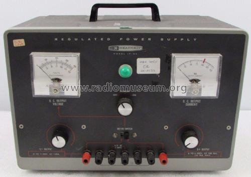
Table 2 — Front-Panel Controls
| Control | Type | Function |
|---|---|---|
| Power switch | Rotary, 3-position: OFF / STANDBY / ON | OFF: no power anywhere. STANDBY: filament transformer energized (tube heaters warming/hot), B+ regulator held off — see Section 4. ON: full operation, B+ available. |
| B+ OUTPUT | Front-panel potentiometer | Sets the regulated B+ output, continuously variable 0 to 400 V DC. Part of the R10–R14 divider chain feeding the 6BH6 control-tube grid (Vol 2). |
| C− OUTPUT | Front-panel potentiometer | Sets the negative bias output, continuously variable 0 to −100 V DC. |
| METER SWITCH | DPDT slide switch | Selects which rail the single voltmeter movement reads: B+ (0–400 V) or C− bias (0–150 V scale, though the supply itself never exceeds −100 V). Does not affect the current meter, which is permanently wired in the B+ line only. |
| D.C. OUTPUT VOLTAGE meter | 1 mA panel movement | Reads whichever rail the METER SWITCH selects, through a precision multiplier resistor (400 kΩ for B+, 150 kΩ for bias — Section 6). |
| D.C. OUTPUT CURRENT meter | 150 mA full-scale panel movement | Reads B+ line current only, continuously, regardless of METER SWITCH position. There is no bias current meter (Section 6). |
| Pilot lamp | Indicator | Lit whenever the power switch is in STANDBY or ON. |
| B+ binding post | Insulated, red | Regulated B+ output. |
| C− binding post | Insulated, black or blue (varies by production run) | Regulated negative bias output. |
| Two COMMON binding posts | Insulated | Return/reference posts for B+ and C− — floatable, not bonded to chassis by default (Section 7). |
| Chassis GND binding post | Uninsulated, bonded to case | True chassis/earth reference. |
| Two filament binding posts | Insulated | 6.3 VAC @ 4 A for DUT tube heaters (Section 8). |
| Rear fuse holder | 3 A fuse | Sole overcurrent protection for the entire unit — see Section 10. |
4.4 Power-On, Warm-Up & STANDBY
4.4.1 Why warm-up matters on this design
The IP-32’s series-pass elements — the two paralleled 6L6 tubes — and its 6BH6 control amplifier and 6X4 bias rectifier are all thermionic devices: they need their cathodes to reach operating temperature before they can conduct predictably. Applying full plate voltage to a cold cathode is universal vacuum-tube bad practice — it accelerates cathode stripping and shortens tube life, and on a regulator tube specifically, a cold cathode also means the regulation loop hasn’t stabilized yet, so the output you’d measure in the first seconds after power-on isn’t trustworthy anyway.
The exact warm-up duration called out in the Heath manual’s own operating instructions wasn’t captured in the research pass behind this volume — treat that number as unconfirmed rather than inventing a precise figure. A conservative 30–60 second pause in STANDBY before advancing to ON is standard practice for tube gear of this class and is consistent with everything the manual does confirm about the STANDBY switch position existing specifically to support this discipline (Section 4.2 below). If you have a copy of the manual’s own recommended warm-up time, follow that instead.
4.4.2 The STANDBY function
STANDBY is not “half on.” It is a deliberate mid-position on the power switch that energizes the filament/heater transformer (tube heaters warming or already hot) while killing B+ entirely — no HV appears at the output posts or anywhere the pass tubes can reach it. This is the single most useful operating feature on the front panel for a bench supply that gets used and re-used across a work session.
Two distinct use cases:
- Warm-up before the first ON of a session. Power switch to STANDBY, wait, then advance to ON. This is the sequence described above.
- Quick pause during a session without a full re-warm. If you need to change a DUT connection, reconfigure the output hookup arrangement (Section 7), or just step away from the bench for a few minutes, drop the power switch back to STANDBY instead of OFF. B+ collapses immediately (subject to the discharge caveats in Section 10 — STANDBY removes the source of B+, it does not instantly drain the reservoir), but the filaments stay hot, so returning to ON afterward gets you back to a regulated, warmed-up output in seconds instead of another 30–60 second warm-up cycle.
⚠ Danger — STANDBY kills the regulated B+ source. It does not discharge the raw ~600 V doubler reservoir or the −300 V reference rail, and it does not make it safe to open the case or touch the output posts. Treat STANDBY exactly like ON for the purposes of “is this unit safe to touch” — the only state that matters for that question is Section 10’s discharge-and-verify procedure, done with the power switch fully OFF and the cord unplugged.
4.4.3 Recommended power-on sequence
- Confirm the pre-power checklist and control positions from Section 2.
- Plug in. Power switch to STANDBY.
- Confirm the pilot lamp is lit and, if the case is open on the bench for observation, that tube heaters are glowing.
- Wait for warm-up (Section 4.1).
- Power switch to ON.
- With nothing connected to the output posts, bring the B+ OUTPUT pot up slowly from zero while watching the current meter. With no external load, the reading should settle near the bleeder’s forced minimum draw of roughly 3 mA (four 27 kΩ/2 W bleeder resistors in series pull that much continuously so the pass tubes never lose control at zero output — Vol 2 §Bleeder, Vol 3 §Protection). A current reading wildly above that floor with nothing connected is itself a basic go/no-go check that something in the regulation loop or output wiring needs troubleshooting before you connect a DUT.
- Set the METER SWITCH and the B+/C− pots per Section 5 for the job at hand.
4.5 Setting B+ and Bias
4.5.1 Two independent pots, one shared meter
The B+ OUTPUT pot and the C− OUTPUT pot are fully independent — you can run B+ alone, bias alone, or both together. What’s not independent is the voltmeter: there is only one 1 mA meter movement behind the METER SWITCH, so you can watch B+ or bias at any instant, never both simultaneously. The current meter has no such limitation — it’s hard-wired into the B+ line and reads continuously regardless of switch position, so in practice you’ll often park the METER SWITCH on B+ (to keep both voltage and current visible together) and only flip briefly to C− to confirm the bias setting.
⚠ Danger — Get in the habit of glancing at the METER SWITCH position before trusting a voltage reading, especially right after someone else has used the bench. A 380 V reading on the voltmeter means something completely different depending on whether the switch is on the B+ scale (routine) or the bias scale (impossible — the bias output tops out at −100 V, so a reading that high on that scale means the switch is actually on B+ and you’ve misread which rail you’re looking at).
4.5.2 Setting B+
- METER SWITCH to B+.
- With the DUT connected per your chosen hookup arrangement (Section 7) — or with nothing connected for a bench check — advance the B+ OUTPUT pot slowly from zero.
- Watch the current meter continuously as you advance the pot, not just the voltmeter. Because there is no active current-limit circuit on B+ (Section 10), the current meter is your only early warning that a DUT is drawing more than expected before something overheats or the fuse lets go.
- Stop advancing well before 400 V if your circuit under test doesn’t need it — there’s no benefit to running higher than the job requires, and every volt above what’s needed is more energy stored in the doubler caps you’ll eventually have to discharge.
4.5.3 Setting bias
- METER SWITCH to C−.
- Advance the C− OUTPUT pot from zero toward the negative bias value your circuit calls for. Bias current is small (1 mA rated) and internally current-limited by design (Vol 3 §Protection), so this pot is inherently gentler to work with than B+ — but the voltage is still hazardous. −100 V across bare skin is a real shock, even though the current path is limited.
- Return the METER SWITCH to B+ once bias is set, so the current meter and B+ voltmeter are both live for the working session.
4.5.4 A practical sequencing note
For a typical breadboard session — powering up a tube stage under test — set bias before B+ where the circuit design calls for it (many tube circuits expect grid bias present before plate voltage is applied, to avoid a moment of zero-bias, high-plate-current stress on the DUT’s own tube). This is circuit-dependent, not an IP-32 characteristic, but it’s worth building into your habitual sequence since the IP-32 makes it easy to set one rail at a time.
4.5.5 Illustrative example — setting up a single-stage triode gain block
This is a generic, illustrative walk-through of the procedure, not a spec from the IP-32 manual — the actual numbers always come from whatever circuit you’re breadboarding. Say you’re characterizing a small-signal triode stage that calls for roughly 250 V on the plate and about −8 V of fixed grid bias:
- Wire the DUT per the series-combined arrangement (Section 7, arrangement C) — plate to B+, grid to C−, cathode to the shared COMMON, COMMON jumpered to chassis GND for simplicity on a first pass.
- STANDBY, warm up, ON.
- METER SWITCH to C−. Bring the C− pot up to roughly −8 V.
- METER SWITCH to B+. Bring the B+ pot up slowly toward 250 V, watching the current meter the whole way per Section 9.3’s table.
- Once settled, confirm the actual plate current against what the tube’s published curves predict for 250 V plate / −8 V grid. A current far outside that expectation means either a miswired DUT or a bias/plate voltage combination that isn’t what you intended — recheck before assuming the tube is simply behaving differently than expected.
This is the same procedure regardless of whether the actual numbers are 250 V/−8 V or 380 V/−35 V — the IP-32 doesn’t care what tube you’re characterizing, only that you bring both rails up under observation rather than slamming a pot to its target and hoping.
4.6 Reading the Meters
Table 3 — Reading the Meters
| Meter | Movement | Range(s) | Multiplier / shunt | Notes |
|---|---|---|---|---|
| D.C. OUTPUT VOLTAGE | 1 mA | 0–400 V (B+) or 0–150 V (C−), selected by METER SWITCH | R24 = 400 kΩ, 1% (B+ scale); R25 = 150 kΩ, 1% (C− scale) | The bias output never exceeds −100 V, so the top third of the 150 V scale is simply unused headroom on this rail — not an indication anything is wrong. |
| D.C. OUTPUT CURRENT | — | 0–150 mA full scale | ≈0.66 Ω series/shunt | Wired permanently in the B+ line. Reads regardless of METER SWITCH position. No equivalent meter exists for bias current (rated at only 1 mA and internally limited, so a meter wasn’t considered necessary in the original design). |
⚠ Danger — These are 60-plus-year-old analog panel movements. Mechanical zero can drift, and at least one restored IP-32 was reported reading roughly 380 V on the panel meter against a true 400 V DC output measured on a calibrated DVM — about 5% low. Don’t trust the panel meter’s absolute accuracy for anything that matters (biasing a tube near its plate-dissipation limit, matching a published circuit’s voltage exactly) without cross-checking it against a known-good external meter first. Vol 5 §Calibration covers re-zeroing the movement and verifying the R24/R25 multiplier resistors.
For routine bench work where “close enough” is fine (setting a tube heater voltage, ballparking a plate supply for a circuit that has margin), the panel meters are perfectly usable once you’ve confirmed roughly how far off they are. For anything precision-dependent, clip a DVM across the output posts and treat the panel meter as a coarse indicator only.
4.7 Output Posts — Floating Commons & Hookup Arrangements
4.7.1 Why “floatable” outputs exist
The IP-32 gives you a chassis GND post and two separate COMMON posts, rather than hard-wiring B+ and C− returns straight to the chassis. This is deliberate: tube circuits routinely need their supply reference point to sit somewhere other than earth ground — a cathode-bias node, a stacked B+/bias arrangement across a single stage, or a return point that floats relative to the rest of the bench. Making the COMMON posts independent, insulated binding posts rather than chassis lugs is what lets you choose that reference point per experiment instead of rewiring the supply.
⚠ Danger — That same flexibility is exactly what makes a floating supply more dangerous than a grounded one, not less. If a COMMON post is not jumpered to chassis GND, there is nothing stopping that post — and everything referenced to it, including your DUT’s “ground” — from sitting at a significant potential relative to the earth-grounded bench, the oscilloscope chassis next to it, or you. Never assume a COMMON post is at ground/earth potential. Verify with a DVM (COMMON post to a known chassis/earth point) before you bridge it to anything else on the bench, and before you touch it with a bare hand. Whether the two COMMON posts are bonded to each other or to chassis GND internally by default wasn’t confirmed against the schematic for this volume — check continuity yourself with the unit unplugged rather than assume either way.
4.7.2 Three common arrangements
The diagram below shows the three hookup patterns called out in this volume: a straightforward positive (B+-only) supply, a straightforward negative (bias-only) supply, and a series-combined arrangement where B+ and C− share one COMMON so a DUT sees both a positive plate rail and a negative grid-bias rail referenced to the same return point.
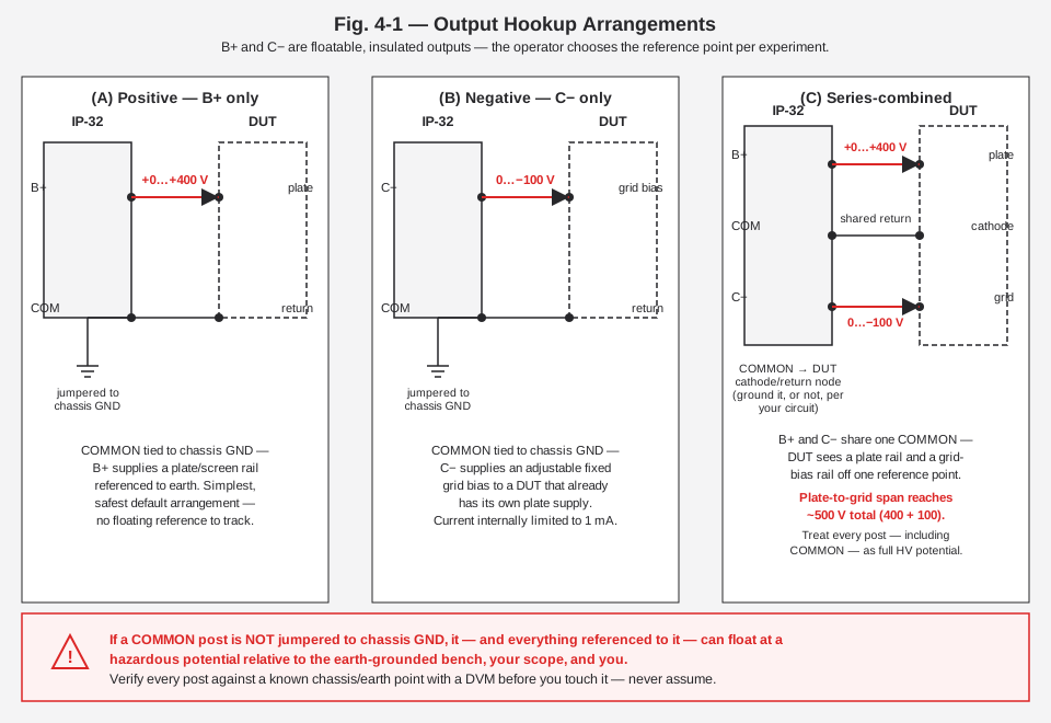
(A) Positive arrangement — B+ only. COMMON jumpered to chassis GND. B+ post supplies 0–400 V positive relative to that shared GND/COMMON point. This is the simplest and safest default: your DUT’s return and the IP-32’s chassis and the bench earth are all the same node, so there’s no floating potential to lose track of. Typical use: powering a plate/screen supply on a stage whose bias is generated locally (cathode-bias resistor) rather than from the IP-32’s C− output.
(B) Negative arrangement — C− only. COMMON jumpered to chassis GND. C− post supplies 0 to −100 V relative to that same shared GND/COMMON point. Typical use: an external fixed-bias supply for a DUT that has its own plate supply but needs an accurate, adjustable negative grid bias — a common role for this output when characterizing a tube’s operating point on a curve tracer setup or bench amplifier.
(C) Series-combined arrangement — B+ and C− together. Both outputs reference the same COMMON post, and that COMMON node becomes the DUT’s cathode/return point rather than chassis GND directly (it may or may not also be jumpered to chassis GND, per your circuit’s needs). The DUT then sees a positive plate rail (0–400 V above COMMON) and a negative grid-bias rail (0 to −100 V below COMMON) simultaneously, off one shared reference — exactly the arrangement a fixed-bias tube amplifier stage needs. Because both rails are referenced to the same point, the total span available between the B+ post and the C− post directly can reach on the order of 500 V (400 V + 100 V). That combined span exceeds either single output’s normal working range, and it means every post in this arrangement, including COMMON itself if it isn’t grounded, must be treated as carrying full HV potential — not just the B+ post.
⚠ Danger — In arrangement (C), don’t let the presence of a “0 V-ish” COMMON node lull you into touching it casually. If COMMON is floating (not jumpered to chassis GND), it sits wherever your circuit puts it relative to earth — and the one-hand rule (Section 10) applies to every post in a floating arrangement, not just the ones with big numbers printed next to them on the meter.
4.8 Filament Output
Two front-panel binding posts supply 6.3 VAC @ 4 A for powering a DUT’s own tube heaters — this is separate from the IP-32’s internal heater supply that runs its own six tubes (that internal supply is covered in Vol 3 §Power Distribution). A few operating notes:
- It is AC, not DC — this is a heater/filament winding, not a rectified supply. Don’t wire it expecting a DC reading on a meter set to DC volts; you’ll read close to zero even though it’s live and can deliver real current.
- 4 A is a hard budget across everything you connect to it. If your DUT circuit has multiple tubes drawing heater current from this output simultaneously, add up their rated heater currents before assuming the IP-32 can supply them all — this output was sized for typical single- or dual-tube breadboard experiments, not for powering a multi-tube chassis’ entire heater string.
- Like the B+ and C− posts, the filament posts are isolated binding posts rather than chassis-bonded — the same floating-reference caution in Section 7 applies if you’re combining the filament supply with a floated B+/C− arrangement on the same DUT.
- 6.3 VAC is a low-hazard voltage by itself, but don’t let familiarity with “it’s just filament voltage” carry over into carelessness elsewhere on the same DUT wiring where a B+ or C− lead may be inches away.
4.8.1 Running this unit alongside the SP-2717A
Jeff keeps the IP-32 and its later sibling, the Heathkit SP-2717A, side by side on the bench. Everything in this volume applies identically to both — they are, electrically, the same supply: both put out 0–400 V DC B+ at 100 mA continuous (125 mA intermittent) and 0 to −100 V bias at 1 mA, both use a pair of 6L6-family tubes as the series-pass element, and both use the same front-panel control layout (OFF/STANDBY/ON, B+ and C− pots, a shared METER SWITCH). They are not a low-current/high-current pair, despite that being a natural-sounding assumption for two supplies that look and behave almost identically — see Vol 1 §Overview and Vol 6 §Cheatsheet for the full lineage. What differs is generation, not output capability: the IP-32 (1962–67) derives its voltage reference from a pair of 0A2 gas-regulator tubes and rectifies its bias supply with a 6X4 tube, while the SP-2717A (1982, Heath-Zenith era) replaces that reference with a solid-state zener-diode reference stack and uses all-silicon rectification throughout. Operationally, that difference is largely invisible from the front panel — the procedure in this volume is the same instrument-to-instrument, and both still carry 6L6-family series-pass tubes that deserve the same STANDBY warm-up discipline in Section 4. Where the generational difference does show up is inside the case (Vol 2, Vol 3) and in what ages/fails over decades of service (Vol 5) — the IP-32’s 0A2 reference tubes and 6X4 bias rectifier are wear items in a way the SP-2717A’s zener stack and silicon rectifiers are not.
4.9 Connecting a DUT and Bringing Up Current
- Power the IP-32 down (STANDBY or OFF) before you land or change any DUT wiring. Never make or break connections at the output posts with B+ or C− live.
- Choose your hookup arrangement (Section 7) and land the DUT’s leads on the appropriate posts — plate/anode to B+, grid-bias node to C− if used, cathode/return to COMMON, heaters to the filament posts if the DUT tube’s heaters are being supplied from the IP-32.
- Double-check polarity and post assignment against your circuit before re-powering. A B+ lead landed on what you intended to be a low-voltage node is exactly the kind of mistake this checklist exists to catch.
- Power switch to STANDBY, warm up (Section 4), then to ON, following the sequence in Section 4.3.
- METER SWITCH to B+. Bring the B+ OUTPUT pot up from zero slowly, watching the current meter continuously as you go — not just glancing at it after you’ve already reached your target voltage.
- Because the IP-32 has no active current limit on B+ — protection is the rear 3 A fuse and the pass tubes’ own dissipation limit, nothing more (Vol 3 §Protection) — a shorted or badly-behaving DUT will pull current until the fuse lets go or a tube cooks, not until some polite foldback circuit intervenes. Watch the mA meter as your early-warning system.
- If you’re powering up an unknown or first-build DUT, consider a series current-limiting resistor between the B+ post and the DUT’s plate node while you bring the pot up for the first time, and remove it once you’ve confirmed the circuit behaves as expected. This is standard bring-up practice for any unknown load on an HV supply that lacks active limiting, and it’s cheap insurance against a wiring mistake turning into a blown fuse or a cooked pass tube.
- Set bias per Section 5.2 if the circuit uses it.
- Once running, never sustain B+ current above 100 mA — that’s the continuous rating; 125 mA is the intermittent maximum, not a number to run at steadily (Section 10.4).
⚠ Danger — Steps 1 and 4 above are not interchangeable in order. Wiring changes happen with the supply down; power-up happens only after wiring is confirmed. Reversing this habit — “just touching up” a connection while the supply is live because the voltage “isn’t that high yet” — is how experienced people get hurt on gear like this.
4.9.1 Reading the current meter as you step up
The mA meter is doing double duty during bring-up: it’s telling you what your circuit is actually drawing, and it’s telling you whether the regulator itself is behaving. A few patterns worth knowing:
Table 4 — drawing, and it's telling you whether the regulator itself is behaving. A few patterns worth knowing
| What you see | Likely meaning |
|---|---|
| Current sits near the ~3 mA bleeder floor as B+ climbs, DUT drawing nothing yet | Normal — you haven’t reached the DUT’s turn-on point, or the DUT genuinely draws very little at this operating point |
| Current climbs smoothly and roughly tracks what your circuit’s expected plate resistance predicts | Normal, healthy bring-up |
| Current jumps sharply at some threshold voltage, then holds | Could be normal (a tube DUT reaching cutoff/conduction transition) or could indicate a marginal short — cross-check against what the circuit should do before continuing |
| Current climbs continuously with no sign of leveling off as you approach your target voltage | Stop advancing the pot. This is the signature of a low-resistance fault somewhere in the DUT wiring or the DUT itself — investigate before going further, not after the fuse blows |
| Current pins near or above 100 mA well before you’ve reached your intended B+ setting | Stop. Back the pot down immediately. You are at or past the continuous rating and risking the pass tubes, the fuse, and the transformer |
None of this replaces actually understanding your DUT circuit’s expected operating point before you power it up — it’s a safety net, not a substitute for doing the math first.
4.10 HV Safety — This Section Is Not Optional
This instrument is built around genuinely lethal voltages, and it is built to a design era (kit
electronics, mid-1960s) that predates a lot of the safety interlocking modern gear takes for granted.
Read this section fully — not skimmed — before your first hands-inside-the-case session, and re-read it
after any time away from the bench. Everything here is reinforced by, and should be read alongside,
the hub-wide _shared/legal_ethics.md, which covers mains safety,
HV discipline, and hazardous-materials handling common to all the vintage tube gear in this collection.
4.10.1 The voltages in this box
Table 5 — The voltages in this box
| Node | Approximate potential | Why it’s there |
|---|---|---|
| Raw B+ (doubler output, on the 6L6 plates) | ≈600 V DC, no load | Full-wave silicon voltage doubler off a 210 V transformer winding — feeds the series-pass tubes before regulation drops it to the set output (Vol 2, Vol 3). |
| Front-panel B+ output | 0–400 V DC, regulated | The output you actually work with. |
| Internal −300 V reference rail | −300 V DC | Developed by the two 0A2 gas-regulator tubes off the 6X4 bias rectifier; feeds the reference/bias chain (Vol 2 §Regulation Loop). |
| Internal −150 V reference rail | −150 V DC | The other 0A2 tap; also the 6BH6 control tube’s cathode reference. |
| Front-panel C− output | 0 to −100 V DC | Internally current-limited to ~1 mA — lower shock-current risk than B+, but still a real HV shock at the voltage level. |
| Regulator screen supply | ≈230 V DC | Selenium-rectified, feeds the 6L6 screen grids. |
Every one of these is present whenever the unit is plugged into mains and the power switch is in STANDBY or ON — several (the raw B+, the reference rails) are present even when the front-panel outputs read 0 V, because they exist upstream of the regulation and adjustment pots.
4.10.2 The bleeder will not save you
⚠ Danger — the single most important fact in this volume. The IP-32’s bleeder network — four 27 kΩ, 2 W resistors in series across the B+ rail, from the 6L6 cathodes down to the −300 V rail — exists to force a minimum ~3 mA load on the regulator so the series-pass tubes never sit in an uncontrolled state at zero output. It is not sized to be a fast safety-discharge path. At 3 mA, draining a charged doubler capacitor bank takes far longer than the few seconds it’s tempting to wait after flipping the switch OFF. Filter capacitors inside this unit can hold a dangerous, potentially lethal charge for a meaningful time after power is removed. Never treat “I switched it off” as equivalent to “it’s safe to touch.”
4.10.3 Discharge procedure before reaching inside
- Power switch to OFF. Unplug the line cord — don’t just switch off, physically remove power.
- Wait — a minute or more buys you nothing certain here given the ~3 mA bleeder rate, so don’t treat waiting alone as a substitute for the next steps.
- Manually discharge the doubler reservoir capacitors (the pair of 70 µF-class cans on the raw B+ / doubler stage — Vol 3 §Rectifier & Filter, Vol 5 §Recap) through a resistor, not a direct short. A common safe approach: a 10 kΩ–100 kΩ, several-watt resistor mounted on an insulated probe or clip lead, touched from the high side of each cap down to chassis/COMMON, held in place for several seconds. Direct-shorting a charged HV cap with a bare screwdriver blade is a known way to weld metal, pit contacts, or throw molten debris — use a resistor.
- Repeat for the negative-rail caps (the 40 µF and 20 µF cans on the bias/reference side) — they sit at a lower voltage than the doubler stage but are still hazardous, and they’re easy to forget because attention naturally goes to the “big number” B+ side first.
- Verify with a DVM across each cap (and across the output posts) before you put a hand anywhere near the chassis. A discharged cap reads at or near 0 V; anything else means keep discharging.
- Only after every relevant node reads at or near 0 V on your own meter — not “probably fine by now” — is it appropriate to open the case or work inside.
4.10.4 The one-hand rule
⚠ Danger — Whenever you must probe inside a powered — or recently powered, unverified-discharged — IP-32, keep one hand in your pocket or behind your back. The danger with HV isn’t the voltage alone; it’s a current path across your chest, hand-to-hand, that can involve the heart. A shock that takes the path down one arm and out through your feet is bad. A shock that crosses your chest because both hands were in the chassis is potentially fatal. This rule costs you nothing and applies every time, not just on days you “feel like it might be live.”
Additional standing practice:
- Stand on a dry, insulating surface (rubber mat) if one is available.
- Keep the other hand, and ideally your whole body, clear of grounded metal (the bench frame, a grounded lamp, a metal stool) while the free hand probes.
- Remove rings, watches, and metal bracelets before working inside — a ring bridging a live node to a grounded chassis edge is a classic burn injury.
- Never work alone on a first power-up of an unfamiliar or freshly-repaired unit if you can avoid it.
4.10.5 Never exceed 100 mA sustained
⚠ Danger — The B+ output is rated 100 mA continuous, 125 mA intermittent maximum. There is no electronic foldback or active current-limit circuit protecting B+ — the only things standing between a sustained overcurrent condition and real damage are the rear 3 A fuse (which protects against a hard fault, not against a DUT that’s merely drawing more than it should) and the physical heat-dissipation limit of the two 6L6 pass tubes. Beyond both of those, restorer reports single out the IP-32’s power transformer as somewhat under-rated for sustained duty — running the unit hard at or above its rated current for extended periods is a known way to cook the primary winding on a transformer that is, at this point, difficult to source as a replacement. Treat 100 mA as a ceiling for continuous work, not a target to run at by default, and use 125 mA only for the brief, intermittent excursions the spec actually describes.
4.10.6 Multiple floating cathodes at high potential
The IP-32’s own internal heater supply is built from a transformer with four isolated windings: the two 6L6 pass tubes share a single winding (their plates, cathodes, and heaters are all directly paralleled), and the remaining three windings serve the 6X4, the 6BH6, and the pilot lamp plus the front-panel 6.3 VAC filament output — precisely because the cathodes of those tubes don’t all sit at the same potential. Several of them float well above chassis ground by design. If you’re probing inside the case rather than just at the output posts, remember that a heater pin can be carrying a meaningfully elevated DC potential relative to chassis even though it’s only a 6.3 V AC winding in isolation — it’s the winding-to-chassis potential that matters, not just the voltage across the winding itself. Don’t assume any internal node is “just filament voltage and therefore safe” without checking what it’s referenced to.
4.10.7 Selenium and old-electrolytic hazards
The screen-supply selenium rectifiers are a wear item on this design and, like any selenium rectifier,
can release an acrid, toxic odor if they fail catastrophically — if you ever smell burning selenium,
power down and ventilate immediately rather than continuing to operate the unit. Old electrolytics that
have vented or leaked carry an alkaline, skin-irritating electrolyte — wear nitrile gloves when
handling a chassis with visible cap residue. Both hazards, and the general handling of pre-1980
components (asbestos-sleeved resistors, PCB-bearing transformers on some period gear), are covered in
_shared/legal_ethics.md — read it alongside this section, not
instead of it.
4.11 Shutdown Procedure
- Bring the B+ OUTPUT and C− OUTPUT pots back down to zero before switching power off or disconnecting a DUT — this avoids dumping a sudden transient into whatever’s still wired to the posts.
- Power switch to STANDBY briefly if you plan to return to the bench soon, or straight to OFF if the session is done.
- Unplug the line cord.
- If you’re about to work inside the case, or disconnect a DUT that’s been running at meaningful B+, follow the full discharge-and-verify procedure in Section 10.3 before touching anything.
- If you’re simply done for the day and not opening the case, no further action is required — but don’t assume the unit is “safe to touch inside” tomorrow just because it sat unplugged overnight. Re-verify with a meter at the start of the next session if you’re going to be working past the front panel.
4.12 DON’Ts — Quick Reference
Table 6 — DON'Ts — Quick Reference
| Don’t | Why |
|---|---|
| Don’t touch output posts, chassis screws, or reach inside the case within minutes of shutdown | Raw B+ reservoir caps hold ~600 V; the bleeder draws only ~3 mA and is not a fast-discharge path — see Section 10.2–10.3 |
| Don’t trust a voltage reading without first checking METER SWITCH position | Same 1 mA movement reads 0–400 V on B+ or 0–150 V on C− depending on the switch — misreading which scale you’re on leads to setting the wrong pot |
| Don’t sustain B+ current above 100 mA | That’s the continuous rating; 125 mA is intermittent-only, and the power transformer is reportedly under-rated for sustained high-current duty |
| Don’t assume a COMMON post is at ground/earth potential | Outputs are deliberately floatable/insulated; verify with a DVM before bridging a COMMON post to anything else on the bench |
| Don’t apply B+ to a cold, unwarmed DUT tube | Cold-cathode plate voltage accelerates cathode stripping and shortens tube life — use STANDBY to warm up first |
| Don’t work inside the chassis with both hands, jewelry on, or standing on grounded metal | The one-hand rule exists to keep any accidental shock path off your chest — Section 10.4 |
| Don’t rely on “I switched it off a minute ago” as proof the unit is discharged | Bleeder rate (~3 mA) makes that assumption false; discharge manually and verify with a meter every time |
| Don’t substitute metal-envelope 6L6/6L6GA/6L6GB for 6L6GC at high-dissipation settings | ~19 W metal tubes can be over-dissipated where the 6L6GC’s 30 W rating has margin — Vol 5 §Recap |
| Don’t change DUT wiring at the output posts with B+ or C− live | Make or break connections only with the power switch in STANDBY or OFF |
| Don’t ignore a burning-selenium smell | The screen-supply selenium rectifiers are a known wear item and can release a toxic odor on failure — power down and ventilate |
Sources
- Heathkit IP-32 assembly & operation manual scans — archive.org (https://archive.org/details/Heathkit_IP-32_HV_Power_Supply), vintage-radio.info (https://www.vintage-radio.info/download.php?id=212), elektrotanya (https://elektrotanya.com/heathkit_ip-32_regulated_power_supply.pdf/download.html).
- Bob Eckweiler (AF6C), “Heathkit of the Month #67 — IP-32 Bench HV Power Supply,” OCARC RF newsletter, Aug 2015 — https://www.w6ze.org/Heathkit/Heathkit_067_IP32.pdf
- radiomuseum.org, Heathkit IP-32 — https://www.radiomuseum.org/r/heath_regulated_power_supply_ip_5.html
- pudar.net, “Heathkit IP-32 Restoration” (recap values, selenium-to-silicon conversion, transformer under-rating, STANDBY switch contact notes) — https://pudar.net/heathkit-ip-32-restoration/
- Antique Radio Forums, IP-32 repair thread (leaky 0.047 µF coupling cap, panel-meter re-zero report) — https://antiqueradios.com/forums/viewtopic.php?t=440
- Chuck Penson, Heathkit Test Equipment Products (styling/production notes, as cited by AF6C above).