Heathkit IP-32 HV Power Supply · Volume 5
Heathkit IP-32 — Vol 5: Calibration & Refurbishing
A 60-year-old kit-built supply that once flexed to 600 V raw B+ does not forgive a discharge step skipped for convenience.
This volume is the service bench companion to Vol 2 (How It Regulates) and Vol 3 (Inside This Unit) — read those first if the 6L6/6BH6/0A2 regulation loop or the doubler/screen/bias rectifier chains are unfamiliar. Everything below assumes the reader already knows what the circuit does; this volume is about what wears out, how to fix it, and how to prove the fix worked on a specific chassis that is now 59–64 years old as of this writing.
The tool-agnostic bench-safety rules for this whole project — mains GFCI, isolation transformers, variac
reform, hazardous materials in pre-1980 gear — live in _shared/legal_ethics.md.
Read that document once; it is not repeated here except where the IP-32’s specific voltages change the
numbers.
5.1 Safety First — Before You Touch Anything Inside This Chassis
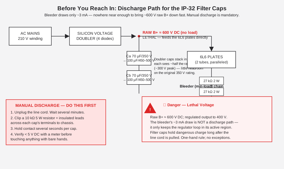
⚠ Danger — This section is not boilerplate. Skip it and you can die. The IP-32’s raw B+ rail sits at approximately 600 V DC across the doubler filter capacitors, and the regulated output is adjustable to 400 V DC. Both are lethal under the wrong conditions (dry skin, a good ground path, a moment of inattention). Read this section before every single service session on this unit, not just the first one.
5.1.1 Why the Bleeder Doesn’t Save You
It is tempting to assume that because the IP-32 has a bleeder — the four 27 kΩ/2 W resistors wired in series from the 6L6 cathodes down to the −300 V rail (Vol 3 covers this network in the outputs/metering section) — the supply is “self-discharging” once unplugged. It is not, or at least not fast enough to matter.
That bleeder chain draws roughly 3 mA continuously. Its job is to guarantee a minimum load on the series pass tubes so the regulator never loses control at very low output settings (see Vol 2’s discussion of why a series regulator needs a minimum load to stay in its active region) — it is a regulation feature, not a safety feature. Do the arithmetic on a 70 µF cap sitting at a few hundred volts, discharging through a few kΩ of bleeder resistance, and the time constant is measured in tenths of a second to a few seconds for the bulk of the charge — which sounds fine, except the bleeder path is only one of several parallel filter sections, some of which are more lightly loaded, and a supply that has sat unused for years may have a bleeder resistor that has drifted or opened entirely. Never trust the bleeder as your only discharge path. Treat this chassis exactly as it deserves to be treated: as if it could still be live minutes — or hours — after the cord left the wall.
5.1.2 Discharge Procedure
Follow this sequence every time before removing the bottom cover or reaching past the chassis lip:
- Unplug the line cord. Do not rely on the OFF/STANDBY/ON rotary switch alone — it is a convenience switch, not a safety disconnect, and STANDBY specifically leaves the filament transformer and (per Vol 3’s coverage of the switch wiring) parts of the AC side energized by design.
- Wait. A few minutes lets the bleeder do what it can on its own before you add a discharge tool.
- Build (once) or grab a discharge stick: a 10 kΩ, 5 W (or higher) resistor with an insulated handle and a pair of well-insulated clip leads, one end permanently bonded to a ground clip. Do not use a screwdriver shorted directly across cap terminals — that dumps the full stored energy instantaneously into an arc, which is hard on the capacitor, hard on the PC traces/terminals, and startling enough to make you flinch into something else in the chassis.
- Discharge each electrolytic individually — the doubler pair, the screen-supply filter, and the bias filter are physically separate cans/sections and do not necessarily share a fast bleed path with each other. Bridge each cap’s positive terminal to chassis ground through the discharge resistor and hold contact for several seconds.
- Verify with a meter. Before touching anything bare-handed, confirm each node reads under about 5 V DC with a DMM. If it doesn’t, you missed a cap or a filter section — go back to step 4.
- One-hand rule for everything after that. Keep your other hand in your pocket or behind your back any time you are probing inside this chassis with power applied for calibration work (Vol 4 covers live in-circuit HV measurement procedure in detail). Wear safety glasses. Work on an insulated mat if you have one.
5.1.3 One More Reminder on Floating Cathodes
The IP-32’s filament transformer has four isolated secondary windings specifically because the pass-tube and control-tube cathodes float at high potential relative to chassis ground (Vol 3 has the full winding table). That means heater wiring you might otherwise assume is “just 6.3 V AC, harmless” can be riding on top of a few hundred volts DC relative to the chassis. Don’t assume any wire in this chassis is low-voltage just because it terminates on a filament pin — check what it’s riding on first.
5.2 Bench Setup for This Work
Before pulling the cover, stage the bench the same way for every session on this unit:
Table 1 — Before pulling the cover, stage the bench the same way for every session on this unit
| Item | Why it’s on the list |
|---|---|
| Isolation transformer (500 VA+) | The IP-32’s chassis is not hot-chassis in the classic AC/DC-radio sense, but any unfamiliar 60-year-old chassis gets isolated as a default per _shared/legal_ethics.md. |
| Variac | For the slow bring-up in the Post-Refurb Verification Checklist below, and any time the supply has sat unused for an extended stretch. |
| GFCI-protected outlet strip | Non-negotiable per the hub safety doc; if this unit trips a 5 mA GFCI after a recap, suspect a leaky bypass/line cap elsewhere in the AC input stage, not a bad GFCI. |
| Reference DMM, 0.5% accuracy or better, with HV-rated (≥600 V) leads | Used for every calibration step below — the panel meter is what’s being calibrated, not the reference. |
| 10 kΩ 5 W discharge resistor + insulated clip leads (built once, kept on the bench) | Safety First above — the single most-used tool for this instrument. |
| ESR meter or capacitance/leakage tester | For triaging which of the three filter cans actually need replacing versus which are still within spec, and for checking the ~0.047 µF coupling cap. |
| Tube tester (mutual-conductance, e.g. the project’s Heathkit TT-1) | For checking the 6L6 pair, 6BH6, and 6X4 before assuming a regulation fault is a tube fault — remembering, per the pass-tube dissipation discussion below, that a tube tester’s static check does not exercise a tube at full continuous plate dissipation. |
| Dummy load resistor(s) rated for the ~40 W a 100 mA / 400 V full-load test implies | For the load-regulation verification step in the Post-Refurb Verification Checklist. |
5.3 Recapping the Filter Electrolytics
5.3.1 What’s Original, What’s Tired
Every electrolytic in an IP-32 built in the 1960s is now well past any electrolytic capacitor’s realistic service life — wet-slug and foil electrolytics of that era typically start showing dried-out electrolyte, rising ESR, and reduced effective capacitance well inside 30–40 years, and this supply is pushing double that. Even a unit that “still works” is very likely running on filter capacitance that has drifted low and ESR that has climbed, both of which show up as increased ripple, softer regulation under transient load, and (worst case) reduced voltage margin on the doubler side where the caps are already living close to their rating.
The three original electrolytic values reported for this design are 70 µF at 350 V (the main doubler filter pair), 40 µF, and 20 µF — the latter two filtering the screen-supply and bias sections respectively. Treat these as a starting point, not gospel: the full cap-by-cap parts-list transcription against the assembly manual has not been independently re-verified for this volume, so confirm every position, value, and voltage rating against the actual Heathkit IP-32 assembly manual’s parts list and schematic before ordering anything. The manual is on archive.org, vintage-radio.info, and elektrotanya (all cited in Sources below) — pull the parts list page before you buy.
Before assuming every can needs to go, measure what’s actually there — an ESR meter or a bridge-style capacitance/leakage tester will tell you whether a given can is still within a reasonable fraction of its marked value with acceptable ESR, or whether it’s dried out. Log the readings the same way the project’s writing-style convention calls for elsewhere in this hub — a measured before/after, not a vague “it was bad”:
Log example format: “Doubler cap Ca measured 41 µF / ESR 38 Ω against 70 µF/350 V marked — replaced with 100 µF/500 V axial electrolytic. Doubler cap Cb measured 58 µF / ESR 6 Ω against the same marking — within a more reasonable range but replaced anyway given its position on the highest-voltage node in the chassis.”
A cap that measures close to its marked value with low ESR is not automatically safe to leave in place if it’s sitting at or near its original voltage rating with little derating margin — see the doubler-side discussion below. A cap that measures well outside its marked value or shows high ESR is unambiguous: replace it regardless of position.
5.3.2 Recap BOM
Table 2 — Recap BOM
| Position / role | Original value | Original voltage | Suggested replacement | Suggested voltage | Notes |
|---|---|---|---|---|---|
| Main B+ doubler filter (×2, series-stacked) | 70 µF | 350 V | 100 µF | 450–500 V | Each cap sees roughly half the ~600 V raw rail (~300 V peak); original 350 V rating leaves little headroom — bump voltage, not just value. Confirm polarity/orientation against the chassis before removal. |
| Screen-supply filter | 40 µF | (confirm) | 47 µF | (confirm — ≥250 V recommended) | Filters the selenium half-wave rectified ~230 VDC screen rail feeding the 6L6 screens. |
| Bias-supply filter | 20 µF | (confirm) | 22 µF | (confirm — ≥400 V recommended given the ~380 V 6X4 output ahead of the 0A2 regulators) | Sits ahead of the 0A2 regulator stages on the negative rail. |
⚠ Danger — Every value and voltage in this table other than the two confirmed originals (70 µF/350 V, and the general recap-target logic) should be cross-checked against the manual’s actual parts list before you place an order. Do not assume the table above is a complete or final BOM — it is a starting point built from restorer reports, not a transcription of the schematic’s every capacitor.
5.3.3 Voltage Derating on the Doubler Side
The reasoning behind bumping the main filter caps from 350 V to 450–500 V deserves a sentence of explanation rather than just a table cell. In a full-wave voltage doubler, the two filter capacitors stack in series across the ~600 V raw rail; each one individually only has to hold roughly half that total, i.e., something in the neighborhood of the peak of the 210 V transformer winding it’s charging from. That puts the original 350 V rating right up against what each cap actually sees in normal operation — reasonable engineering for a 1962 design with fresh caps and generous safety margins baked into the tube-of-the-era manufacturing tolerances, but very little margin left after six decades of dielectric aging, voltage-rating creep in modern manufacturing tolerances, and a bench that may see line voltage a few percent high. Modern 450–500 V rated electrolytics cost only marginally more than 350 V parts in this capacitance range and buy back real margin. Do not go the other direction and try to save money with a lower-voltage substitute here — this is the highest-voltage, highest-risk position in the whole recap.
5.3.4 Physical Swap Notes
- Discharge first. See the Safety First section above — this is not optional, and it applies to every one of the three positions in the BOM, not just the doubler pair.
- Photograph before you pull anything. Lead dress, polarity markings, and can orientation all matter for reassembly, especially on cans that are riveted or clamped to the chassis rather than simply through-hole soldered.
- Match negative-lead polarity carefully on the doubler pair — a reversed cap in a voltage-doubler stack will not “just fail,” it can fail explosively under the full raw B+ potential.
- Preserve strain relief and lead length where possible; this is 60-year-old point-to-point/eyelet-board wiring, not a modern PCB, and excess mechanical stress on original solder joints elsewhere in the chassis is its own failure mode.
- Reform is optional but cheap insurance if the supply has sat unused for a long stretch even after the
recap — bring the AC up slowly on a variac with the new caps in place before running at full B+, per the
general reform guidance in
_shared/legal_ethics.md.
5.4 Regulator & Reference Device Wear
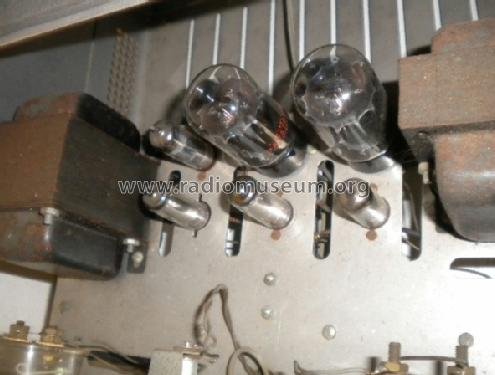
The IP-32’s regulation loop is entirely tube-based — two 6L6 series-pass tubes, a 6BH6 control/error amplifier, and two 0A2 gas voltage-reference tubes, with a 6X4 handling bias rectification (the full loop description is in Vol 2). All five tube types age, and each has a specific, documented failure signature in this design.
5.4.1 Pass Tubes: 6L6 vs. 6L6GC
The two 6L6 series-pass tubes are wired in parallel, plates and cathodes and heaters all directly tied together, acting as a pair of variable resistors that drop the difference between the ~600 V raw B+ rail and whatever the front-panel B+ OUTPUT pot has selected. That dropped voltage, multiplied by the current flowing, is dissipated as heat in the tube envelopes — and this is where tube selection stops being a “any 6L6 will do” question.
Consider the worst case for pass-tube dissipation: the B+ OUTPUT pot set near 0 V, with the design’s full 100 mA continuous rating still flowing (the IP-32’s design goal, per Vol 1/Vol 2, is exactly this — full rated current available across the entire 0–400 V range, unlike the earlier PS-2/PS-3 designs where available current fell as voltage rose). At that operating point, almost the entire raw ~600 V rail is being dropped across the paralleled pass tubes. Split evenly across two tubes, that is roughly 50 mA per tube at roughly 600 V — call it 30 W per tube, worst case, before accounting for the raw rail sagging somewhat under load (the ~600 V figure is the no-load value; loaded it will read a bit lower, which helps, but not by enough to plan around).
That number is not a coincidence relative to tube selection:
Table 3 — That number is not a coincidence relative to tube selection
| Tube type | Rated plate dissipation | Verdict for full-range IP-32 service |
|---|---|---|
| 6L6GC | ~30 W | Correct choice — sits right at the worst-case dissipation figure, with the margin the “GC” suffix was designed to provide. |
| Metal 6L6 / 6L6GA / 6L6GB | ~19 W | Undersized. Can be over-dissipated at high-current, low-output-voltage settings — exactly the operating point a bench supply gets run at constantly during breadboard work with the output pot backed down. |
Use 6L6GC and only 6L6GC in both positions. If a metal-can 6L6 or an early 6L6GA/GB shows up in a unit you’re servicing, replace it even if it still tests fine on a tube tester’s static bias curve — a tube tester does not exercise the tube at 30 W of continuous plate dissipation, and marginal survival on a tester is not the same thing as safe continuous operation at the IP-32’s worst-case operating point.
5.4.2 The 0A2 Reference Tubes
The two 0A2 gas voltage-regulator tubes are the actual voltage reference for this entire supply — each one strikes and holds a roughly 150 V glow-discharge regulation voltage, and the two in series develop the regulated −150 V and −300 V rails that the divider chain and the 6BH6 control grid ultimately compare against (Vol 2 covers the full reference-and-comparison chain; Vol 3 covers the internal anode/cathode pin-jumper fail-safe wiring that makes pulling a 0A2 open the rail rather than pass unregulated voltage).
Gas regulator tubes drift with age — the strike and regulation voltage is not perfectly stable over a multi-decade service life, and a 0A2 that has seen heavy hours can regulate a few volts off its nominal 150 V point even while still striking and glowing normally. Because this reference feeds directly into the zero and 400 V full-scale calibration described below, a 0A2 that has drifted shows up as a calibration that won’t hold — you trim the zero and full-scale points, they check out, and a session or two later they’ve walked off again. If re-trimming the internal divider pots doesn’t produce a stable calibration, or the trim range runs out before you reach 0 V or 400 V, suspect the 0A2 pair before suspecting the divider resistors.
⚠ Danger — 0A2 tubes are unregulated-looking glass envelopes with a visible glow discharge, which makes them easy to forget are part of a high-voltage chain. Handle with the supply fully discharged per Safety First above, same as any other tube pull in this chassis.
5.4.3 The Classic Fault: Leaky ~0.047 µF Coupling Cap
If there is one single fault that shows up over and over in IP-32 repair reports, it is this one. A coupling capacitor — roughly 0.047 µF, running from the 6BH6 control-grid circuit over to the 6L6 cathode side — develops leakage as it ages, and that leakage disrupts the DC bias relationship the zero-adjust and 400 V full-scale adjustments depend on. The symptom is specific and diagnostic: the zero and/or 400 V-adjust trims stop behaving predictably — the output won’t zero cleanly, or the full-scale trim seems to interact strangely with the zero trim, or the output drifts in a way that doesn’t track a simple regulation-loop explanation.
This is worth checking before chasing 0A2 drift or divider-resistor drift, because it is cheap, it is a known quantity in this specific design, and a leaky coupling cap can produce symptoms that look enough like reference-tube drift to send a first-time restorer down the wrong path. Pull the cap, check it on a capacitance/leakage meter or simply substitute a known-good modern 0.047 µF film cap of appropriate voltage rating, and see if the calibration behavior normalizes before replacing anything more expensive.
5.4.4 Selenium Screen Rectifiers → Silicon + Series R
The IP-32’s screen supply for the 6L6 pass tubes is half-wave rectified by two selenium rectifiers wired in series, off a 175 V transformer winding, filtered to roughly 230 VDC. Selenium rectifiers are a known wear-out item across the entire vintage-electronics field, not just this supply — they degrade with age and heat cycling, their forward drop rises as they degrade, and they are a documented (if low-probability) source of acrid-smelling off-gassing as they fail, quite apart from simply losing rectification capability.
The standard restoration fix is to replace the selenium stack with silicon diodes plus a series resistor sized to make up the forward-voltage difference — selenium rectifiers typically drop meaningfully more forward voltage per junction than a silicon diode, so a straight silicon swap without the compensating resistor will push the screen-supply DC voltage higher than the 230 V design target. Size the series resistor (and confirm its power rating against the screen current, which the 6L6 screens draw through 100 Ω parasitic-suppression resistors per the schematic) to land back near the original ~230 V figure.
The original silicon B+ doubler diodes (four of them, in the voltage doubler feeding the raw ~600 V rail) can also be swapped for modern 1N400x-class rectifiers as routine preventive maintenance, though silicon diodes of that era are generally more durable than selenium and less urgent to replace unless one has actually failed.
5.4.5 6BH6 Control Tube & 6X4 Bias Rectifier
Less commonly reported as a wear item, but worth a mention: the 6BH6 control/error amplifier tube (cathode tied to the regulated −150 V rail, plate feeding the paralleled 6L6 control grids through a 470 kΩ resistor) and the 6X4 bias-rectifier tube (full-wave rectifying the 600 V-CT bias winding down to roughly 380 V ahead of the 0A2 regulator pair) are both conventional tubes without the specific documented failure signatures that the 6L6/0A2/coupling-cap/selenium items above have. Treat them the same way you’d treat any tube in a 60-year-old chassis: check emission/transconductance on a tube tester if regulation or bias behavior is suspect and the more specific faults above have been ruled out, and keep a spare of each on the shelf given how central both are to the regulation loop.
5.5 Meter Re-Zero & Calibration
The IP-32’s two front-panel meters — a 150 mA full-scale current meter with roughly 0.66 Ω of series/shunt resistance, and a 1 mA voltmeter movement switched by the DPDT METER SWITCH between a 400 kΩ 1% multiplier (0–400 V on B+) and a 150 kΩ 1% multiplier (0–150 V on C−) — are analog movements, and analog movements drift mechanically over 60 years regardless of what the underlying circuit is doing. Calibration on this supply is therefore a two-layer problem: the meter’s own zero and reading accuracy, and the regulator’s actual output voltage at the front-panel controls’ zero and full-scale settings. Fix them in that order — there is no point trimming the regulation divider to make a miscalibrated meter agree with itself.
5.5.1 Mechanical Zero
Before touching any internal trim, check the meter face itself with the supply unpowered (and, per Safety First, fully discharged). Every analog panel meter has a small mechanical zero-adjust screw on the meter face, usually just below or above the pointer pivot, accessible without opening the case. With no current flowing and no voltage applied, the pointer should rest exactly on the meter’s own zero mark; if it doesn’t, correct it with the mechanical screw before doing anything else. This step is free, takes under a minute, and a meter with a mechanical zero error will throw off every subsequent electrical calibration step by exactly that offset.
5.5.2 The R10–R14 Divider: Zero and 400 V Trim
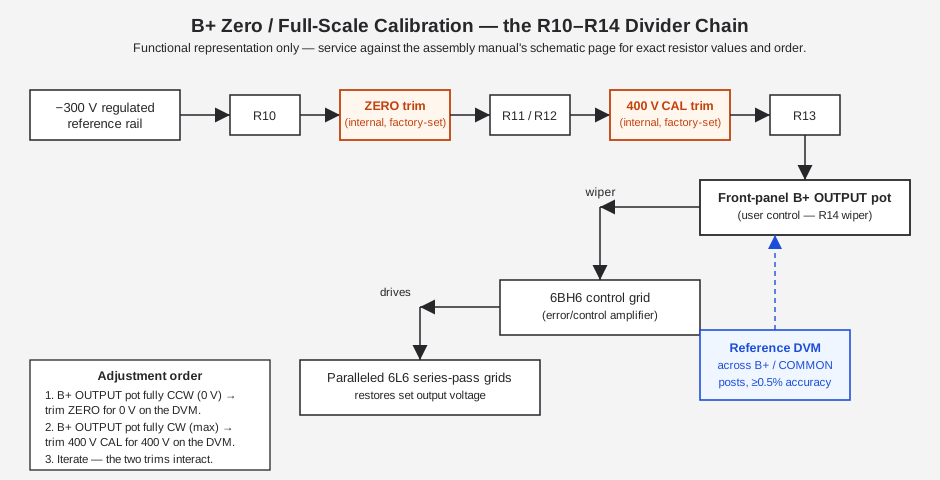
The B+ zero point and 400 V full-scale point are set by two internal trimmer potentiometers sitting in a divider network (referenced in the schematic in the R10–R14 range) between the regulated −300 V reference rail and the 6BH6 control-grid circuit, with the front-panel B+ OUTPUT pot forming part of the same chain. The exact resistor-by-resistor order and values are a schematic-level detail — pull the actual assembly manual page before working on a real unit rather than relying on a generic description — but the functional relationship is straightforward and is what the diagram below shows.
Procedure:
- Connect a known-good reference DVM (0.5% accuracy or better) across the B+ and COMMON output posts. Do not trust the panel meter for this step — it’s exactly what you’re calibrating.
- With the B+ OUTPUT pot turned fully counter-clockwise (minimum), adjust the internal zero trim until the DVM reads 0 V.
- With the B+ OUTPUT pot turned fully clockwise (maximum), adjust the internal 400 V trim until the DVM reads 400 V.
- Iterate. These two trims interact — tightening the zero point can shift the full-scale reading slightly and vice versa, because they share part of the same divider chain. Go back and forth between steps 2 and 3, a small nudge at a time, until both ends hold simultaneously.
- Spot-check one or two mid-range points (e.g., 100 V, 250 V) against the DVM once zero and full-scale hold. The divider should be reasonably linear if the individual fixed resistors (R11/R12/R13 in the diagram above) haven’t drifted; a mid-range point that’s noticeably off while the endpoints are correct points at a drifted fixed resistor in the chain rather than a trim-pot issue.
⚠ Danger — This entire procedure is done with the supply live and the B+ OUTPUT pot swept across its full 0–400 V range. Follow the one-hand rule, keep the reference DVM leads well clear of your other hand, and never reach into the chassis to adjust an internal trim while your other hand is anywhere near the output posts or probe tips.
5.5.3 Verifying R24 / R25
Because the panel voltmeter’s range is set by a single 1 mA movement switched between R24 (400 kΩ, 1%) on B+ and R25 (150 kΩ, 1%) on C−, a drifted multiplier resistor will produce a panel-meter reading that’s proportionally off across the entire range rather than just at one endpoint — unlike the divider-chain trim error above, which tends to show up more at the extremes. If the panel meter disagrees with a reference DVM by a roughly constant percentage across several points on the range (rather than mostly at one end), check R24 and R25 with an ohmmeter (out of circuit, or accounting for the rest of the meter circuit if measured in-circuit) before assuming the meter movement itself is at fault.
One documented real-world data point: a restored IP-32 was reported reading 380 V on the panel meter when the true output, verified against a DVM, was 400 V — roughly a 5% low error. That magnitude is consistent with either a modest mechanical zero/linearity drift in the meter movement or a small drift in the R24 multiplier value; it is not consistent with a gross fault, and it’s a useful benchmark for what “needs re-zeroing” looks like on this design versus what would indicate an actual failed component.
5.5.4 Iterating Zero ↔ Full-Scale — a Worked Checklist
Table 4 — Iterating Zero ↔ Full-Scale — a Worked Checklist
| Step | Action | Target | If it won’t hold |
|---|---|---|---|
| 1 | Mechanical zero, meter unpowered | Pointer on meter’s own zero mark | — |
| 2 | B+ pot min, trim internal ZERO | DVM reads 0 V | Suspect leaky 0.047 µF coupling cap (see above) |
| 3 | B+ pot max, trim internal 400 V CAL | DVM reads 400 V | Suspect 0A2 drift or divider resistor drift |
| 4 | Repeat 2–3 until both hold | Both ends stable within a couple of adjustment passes | If it never converges, check 0A2s and coupling cap before assuming a bad trim pot |
| 5 | Spot-check mid-range (100 V, 250 V) vs. DVM | Reasonably linear | Fixed divider resistor (R11/R12/R13) may have drifted |
| 6 | Compare panel meter to DVM across the range | Agreement within meter’s own rated accuracy | Check R24 (400 kΩ 1%) multiplier and meter mechanical linearity |
5.6 Common Failures & Gotchas
Beyond the specific wear items above, a handful of failure modes and quirks recur often enough in IP-32 service reports to be worth a standing reference table.
5.6.1 Failure-Mode Table
Table 5 — Failure-Mode Table
| Symptom | Likely cause | Fix |
|---|---|---|
| Zero-adjust or 400 V-adjust behaves erratically or won’t hold | Leaky ~0.047 µF coupling cap (6BH6 grid to 6L6 cathode circuit) | Replace the coupling cap with a known-good modern film cap of the correct value/voltage |
| Load regulation drifts outside the ±1% spec, or set-points won’t stay calibrated session to session | 0A2 reference tube drift/wear | Check regulation and re-trim; swap the 0A2 pair if re-trimming doesn’t hold |
| Rising ripple/hum above the <10 mV spec | Filter electrolytics dried out / high ESR (60+ year-old caps) | Recap per the BOM above |
| Screen-supply voltage drifting high, or screen rail failing outright | Selenium screen rectifiers degrading with age | Replace with silicon diodes + series resistor sized to restore ~230 V |
| Pass tube runs unusually hot, especially with B+ OUTPUT backed toward 0 V under load | Metal-can 6L6/6L6GA/6L6GB in service instead of 6L6GC (undersized ~19 W dissipation vs. the ~30 W worst case) | Replace both pass tubes with 6L6GC |
| Primary or transformer running hot under sustained heavy load | The main power transformer is somewhat under-rated for this design by modern standards | Do not sustain overcurrent operation; respect the 100 mA continuous / 125 mA intermittent rating as a real limit, not a suggestion |
| STANDBY position doesn’t cleanly kill/restore B+, crackling or intermittent behavior at the switch | STANDBY switch contact oxidation | Clean and re-tension the switch contacts |
| Audible hum louder than expected, or hum that changes with AC lead dress | AC wiring routing too close to sensitive low-level stages | Re-route AC leads away from the control-amplifier / reference circuitry |
| Panel meter reads consistently a fixed percentage off a reference DVM across the whole range | Drifted R24 (400 kΩ, B+) or R25 (150 kΩ, C−) multiplier resistor, or meter movement linearity | Verify R24/R25 with an ohmmeter; re-zero mechanically; replace multiplier resistor if out of the 1% tolerance band |
| No B+ output at all, fuse intact | Failed silicon doubler diode, open filter cap, or a pass tube that has lost emission entirely | Work back from the raw B+ node with the supply discharged; check doubler diodes and both 6L6s |
5.6.2 The Under-Rated Power Transformer
Multiple independent restoration reports flag the IP-32’s main power transformer as somewhat under-rated for the design relative to modern expectations — it does the job within the supply’s published ratings, but it does not have generous headroom above them. The practical implication for a restorer or an active user is simple: respect the 100 mA continuous / 125 mA intermittent rating as a real ceiling, not a number to lean against routinely. Sustained overcurrent operation is the way to cook the primary winding on a transformer that is hard to source a direct replacement for — Heathkit-specific transformers from a discontinued 1960s kit are not a catalog part, and a burned primary can turn a straightforward electrical repair into a rewind-or-replace project. If a bench session calls for sustained high-current draw near or above the rated maximum, keep an eye (or a thermal probe) on the transformer case temperature, and don’t treat the “125 mA intermittent” figure as a number you can hold indefinitely.
5.6.3 STANDBY Switch Contact Oxidation
The rotary OFF/STANDBY/ON switch is a mechanical wear item like any other multi-decade-old rotary switch. STANDBY position is specifically designed to leave the filament transformer energized (keeping the tubes warm and ready) while killing the B+ path — a useful feature for a bench supply that gets warmed up and left idle between uses, but it means that switch position sees a specific set of contacts that may see less wiping action than the full ON/OFF positions over the unit’s life, and contact oxidation there shows up as inconsistent or intermittent STANDBY behavior — B+ that doesn’t fully die, or doesn’t cleanly restore when switched back to ON. Clean and re-tension the contacts as routine restoration maintenance even if the switch “seems to work” — intermittent HV switching is its own hazard, not just an annoyance.
5.6.4 Testing the Bleeder Chain Itself
The four-resistor, 27 kΩ/2 W bleeder chain described in Safety First is itself a wear item worth checking during any refurb, for two separate reasons. First, a drifted-high or open bleeder resistor undermines the minimum-load function the whole chain exists for — if the effective bleeder resistance climbs well above the nominal 108 kΩ total, the pass tubes can lose their guaranteed minimum load at low output settings, which Vol 2 identifies as the condition that lets a series regulator lose control. Second, and directly relevant to this volume’s opening safety section: a bleeder resistor that has drifted or opened is exactly the failure mode that makes the “just wait a few minutes, the bleeder will handle it” assumption dangerous — a chain that should draw ~3 mA and is actually drawing less than that (or nothing, if fully open) leaves the filter caps holding charge longer than expected, silently. With the supply unpowered and already discharged per Safety First, measure the bleeder chain’s resistance with an ohmmeter and confirm it’s still in the neighborhood of its nominal value (four 27 kΩ resistors in series should read close to 108 kΩ total, allowing for each resistor’s own tolerance) before trusting it for anything.
5.6.5 Hum & AC Lead Routing
Some restoration write-ups note improved hum performance from re-routing the internal AC leads away from the low-level control-amplifier wiring. This is standard tube-chassis practice — AC mains wiring induces hum into any nearby high-impedance grid circuit — and worth a look if a recapped, retubed unit still shows more ripple or hum than the <10 mV spec after the electrical wear items above have all been addressed.
5.7 Parts & Tube Sourcing
5.7.1 Tubes
Table 6 — Tubes
| Tube | Role | Sourcing note |
|---|---|---|
| 6L6GC (×2) | Series-pass regulator | Widely available new-production (JJ, Electro-Harmonix, Tung-Sol reissue, Sovtek, and others) through any guitar-amp-tube retailer as well as the usual electron-tube specialty houses — this is one of the most common power tubes in continuous production, unlike almost everything else in this chassis. |
| 6BH6 | Control/error amplifier | A miniature sharp-cutoff pentode, no longer in production — sourced NOS from tube specialty dealers or estate/surplus lots. Keep a spare; it’s central to the whole regulation loop. |
| 0A2 (×2) | Voltage reference | Gas voltage-regulator tubes of this type are long discontinued — NOS only. Check strike/regulation voltage against a known reference if buying used/pulled examples rather than trusting a tube-tester’s basic continuity check, since regulation-voltage drift is exactly the failure mode described above. |
| 6X4 | Bias rectifier | A common miniature full-wave rectifier tube shared across a huge range of 1950s–60s consumer and test gear — comparatively easy to find NOS. |
5.7.2 Passives
- Electrolytic capacitors (recap BOM above): standard modern axial or radial electrolytics in the 100 µF/450–500 V, 47 µF, and 22 µF classes are readily available from general-line electronic distributors; vintage-radio-focused suppliers also stock can-style replacements sized to physically match original Heathkit hardware if chassis-mount appearance matters.
- Selenium rectifier replacements: silicon rectifier diodes plus an appropriately sized series resistor, as described above — the diodes themselves are generic 1N400x-class parts; the series resistor value/power rating needs to be calculated (or measured empirically) against the actual screen-current draw to land back near the original ~230 V screen supply target.
- The ~0.047 µF coupling capacitor: any modern film capacitor of appropriate voltage rating for its position in the circuit is a suitable direct replacement — this is not a value or type that requires anything exotic.
- R24 (400 kΩ) / R25 (150 kΩ) meter multipliers: both originally 1% tolerance parts; if replacement is needed, match the tolerance — these directly set the panel meter’s accuracy and a lower-tolerance substitute reintroduces the calibration drift this volume is trying to eliminate.
5.7.3 What NOT to Substitute Casually
- Don’t substitute a metal-can 6L6/6L6GA/6L6GB for the 6L6GC, even temporarily “just to get it running” — the dissipation math above is not a margin-of-error concern, it’s a can-genuinely-fail-under-normal-use concern at low-output-voltage, high-current bench settings.
- Don’t skip the series resistor when swapping selenium for silicon on the screen rectifiers — a bare silicon substitution pushes the screen supply voltage above its ~230 V design target because silicon drops meaningfully less forward voltage than selenium.
- Don’t guess at the recap BOM’s unconfirmed entries (screen and bias filter voltage ratings) without pulling the manual’s parts list — see the Recap section above.
5.8 Post-Refurb Verification Checklist
Once the recap, tube swap, coupling-cap replacement, and selenium-to-silicon conversion (as applicable) are complete, verify the unit end-to-end before returning it to bench service. This checklist deliberately mirrors the operating-procedure discipline in Vol 4 — a freshly refurbished supply gets the same careful, staged power-up as an unknown unit, not the confident quick-check treatment of a supply you’ve trusted for years.
Table 7 — Post-Refurb Verification Checklist
| Step | Check | Pass criteria |
|---|---|---|
| 1 | Visual inspection, cover off, supply unpowered | No loose leads, no solder bridges, correct cap polarity/orientation, all tubes fully seated |
| 2 | Insulation check (if available) between chassis and AC primary | No continuity / high resistance, confirming no primary-to-chassis short before first power-up |
| 3 | Slow variac bring-up on first power after service | Watch for smoke, unusual smell, or transformer humming abnormally as line voltage climbs |
| 4 | Filament voltage at the front-panel posts | 6.3 VAC ± normal tolerance |
| 5 | Raw B+ at the doubler, no load beyond the bleeder | Roughly 600 VDC, discharged and re-measured safely |
| 6 | Zero-adjust trim | 0 V at DVM with B+ OUTPUT pot at minimum |
| 7 | 400 V full-scale trim | 400 V at DVM with B+ OUTPUT pot at maximum |
| 8 | Mid-range linearity spot-check | 100 V and 250 V settings track DVM reasonably linearly |
| 9 | Load regulation | Output holds within ±1% no-load to full 100 mA load across the 100–400 V range |
| 10 | Ripple/noise | <10 mV, verified on a scope if available |
| 11 | Panel meter vs. DVM agreement | Within the meter’s rated accuracy across the range; re-check R24/R25 if not |
| 12 | Bias (C−) output | 0 to −100 V, 1 mA rating, verified against DVM on the METER SWITCH’s bias position |
| 13 | STANDBY behavior | Filaments stay warm, B+ cleanly drops to zero and cleanly restores on return to ON |
| 14 | Sustained load soak (if the transformer margin above is a concern) | Case temperature on the power transformer stays reasonable under an extended near-full-load run |
Log the before/after values from this checklist the same way any other instrument in this project records
service history — see the CLAUDE.md writing-style convention (measured values, not vague descriptions) and
file the results in this instrument’s 03-outputs/ repair log.
5.9 Cross-Reference: Refurbishing the SP-2717A Sibling
The Heathkit SP-2717A is the same fundamental circuit two generations later in the PS-4 → IP-32 → IP-17 → IP-2717 → SP-2717A lineage — same 0–400 V @ 100 mA (125 mA intermittent) B+ rating, same 0 to −100 V @ 1 mA bias, same dual-meter front panel, same 4×27 kΩ/2 W bleeder concept — but with the reference and rectifier technology updated. Where the IP-32 uses two 0A2 gas voltage-regulator tubes as its reference and two selenium diodes for the screen rectifier, the SP-2717A replaces the 0A2 pair with a zener-diode reference stack and goes all-silicon for every rectifier position — no 6X4, no selenium anywhere in the chassis. Both units keep the tube 6L6-family series-pass element (6L6 in the IP-32, 6L6GC from the factory in the SP-2717A) — that part of the design never went solid-state across the whole lineage.
Practically, this means the recap and pass-tube sections of this volume apply almost unchanged to the SP-2717A refurb (see the sibling dive’s own Vol 5 for its specifics), but the 0A2-drift and selenium-wear sections above are IP-32-and-earlier-specific concerns — the SP-2717A’s zener reference stack and all-silicon rectifiers age differently (zener drift and semiconductor rectifier wear are different failure modes than gas-tube regulation drift and selenium degradation) and don’t call for the same fixes. If Jeff is servicing both units side by side, don’t cross-apply a fix from one dive to the other without checking which generation’s reference/rectifier technology is actually in the chassis on the bench.
Sources
- Heathkit IP-32 assembly & operation manual scans:
- archive.org — https://archive.org/details/Heathkit_IP-32_HV_Power_Supply
- vintage-radio.info — https://www.vintage-radio.info/download.php?id=212
- elektrotanya — https://elektrotanya.com/heathkit_ip-32_regulated_power_supply.pdf/download.html
- Berkeley (image-only scan) — https://experimentationlab.berkeley.edu/sites/default/files/NMR/Equipment/Heathkit%20IP-32_Regulated%20Power%20Supply_Manual.pdf
- Bob Eckweiler (AF6C), “Heathkit of the Month #67 — IP-32 Bench HV Power Supply,” OCARC RF newsletter, Aug 2015 — https://www.w6ze.org/Heathkit/Heathkit_067_IP32.pdf
- radiomuseum.org, Heathkit IP-32 entry (dates, tube list, price, dimensions) — https://www.radiomuseum.org/r/heath_regulated_power_supply_ip_5.html
- radiomuseum.org, Heathkit IP-2717A entry (sibling lineage) — https://www.radiomuseum.org/r/heath_regulated_hv_power_supply_ip_2717a.html
- pudar.net, “Heathkit IP-32 Restoration” (interior photos, selenium/recap/coupling-cap restoration notes) — https://pudar.net/heathkit-ip-32-restoration/
- Antique Radio Forums, IP-32 repair thread (leaky 0.047 µF cap, recap values, 6L6GC dissipation, under-rated transformer) — https://antiqueradios.com/forums/viewtopic.php?t=440
- diyAudio, IP-32 thread — https://www.diyaudio.com/community/threads/heathkit-ip-32-regulated-supply.360274/
- manuals.plus, IP-32 historical/technical overview — https://manuals.plus/heathkit/ip-32-bench-hv-power-supply-manual
- lazyelectrons.wordpress.com, “Heathkit/Zenith SP-2717A Power Supply Restore” (sibling generation, zener reference and all-silicon rectifier detail) — https://lazyelectrons.wordpress.com/2018/06/02/heathkit-zenith-sp-2717a-power-supply-restore/
- Chuck Penson, Heathkit Test Equipment Products (styling names and production date ranges, cited via AF6C’s article above).