Heathkit IP-32 HV Power Supply · Volume 6
Heathkit IP-32 — Vol 6: Cheatsheet & the Generational Pair
Everything on one laminate: specs, warm-up steps, refurb order, HV DON'Ts, and the honest IP-32-vs-SP-2717A comparison.
6.1 How to Use This Volume
This volume is the bench laminate — the page taped inside the lid, not the page you read cover to cover.
Everything here is a synthesis of Vol 1 through Vol 5; nothing new is derived. Where a row needs more
context than a table cell can hold, it carries a detail: Vol N § pointer back to the volume that explains
it.
Read Vol 1–5 once, slowly, before you ever apply mains power to an IP-32. Then keep this volume open while you work. The Danger callouts in this volume are not decorative — the IP-32’s raw B+ bus sits at roughly 600 V DC even though the regulated output tops out at 400 V, and there is no active current-limit circuit protecting the B+ output at all (only the bias line is current-limited). That combination — lethal voltage, no B+ fold-back, and 60+-year-old paper/electrolytic parts — is why this cheatsheet exists.
⚠ Danger — Every number, step, and warning in this volume assumes a competently refurbished unit with a verified-good chassis ground and a 3-A rear fuse fitted. If you have not yet worked through Vol 5 (Calibration & Refurbishing), do not use the “quick-steps” below as a substitute for it.
6.2 Quick Specs — Outputs & Performance
Table 1 — 2. Quick Specs — Outputs & Performance
| Parameter | Spec | detail |
|---|---|---|
| B+ output | 0 – 400 V DC, regulated, continuously variable | Vol 1 §2, Vol 3 §2 |
| B+ current | 100 mA continuous · 125 mA intermittent max | Vol 1 §2, Vol 3 §2 |
| B+ current limiting | None — protected only by the 3 A rear fuse and the 6L6 pass-tube dissipation limit | Vol 2 §4, Vol 4 §3 |
| Raw B+ (internal, pre-regulation) | ≈ 600 V DC no-load on the doubler caps — lethal, not user-accessible in normal operation | Vol 2 §3, Vol 3 §3 |
| Negative bias (C−) | 0 to −100 V DC @ 1 mA, variable | Vol 1 §2, Vol 3 §2 |
| Bias current limiting | Internally current-limited (this is why there is no bias current meter) | Vol 3 §5 |
| Filament output | 6.3 V AC @ 4.0 A, two binding posts | Vol 1 §2, Vol 3 §2 |
| Load regulation | ± 1 % no-load to full-load, 100–400 V DC | Vol 1 §3 |
| Line regulation | ± ½ V output change for a 10 V line change | Vol 1 §3 |
| Ripple / jitter / noise | < 10 mV | Vol 1 §3 |
| Output impedance | < 10 Ω, 1 Hz – 1 MHz | Vol 2 §3 |
| Minimum bleeder load | ≈ 3 mA, always present (4 × 27 kΩ / 2 W bleeder) | Vol 2 §4, Vol 3 §4 |
| Mains input | 105–125 V AC, 50/60 Hz; rear 3 A fuse | Vol 1 §2 |
| Dimensions / weight | 13″ W × 8½″ H × 7″ D; 12 lb (16 lb shipping) | Vol 1 §2 |
| Era / kit price | 1962–1967; kit ≈ $56.95 | Vol 1 §1 |
⚠ Danger — The absence of a B+ current-limit circuit is the single most important fact on this page. Short the B+ output and the only things standing between the pass tubes and destruction are the fuse and however fast you let go of the leads. This is not a “current-limited bench supply” in the way a modern switcher is. Treat every B+ connection as if it were live mains.
6.2.1 Active-device complement (for fault-finding at a glance)
Table 2 — 2.1 Active-device complement (for fault-finding at a glance)
| Device | Qty | Role | detail |
|---|---|---|---|
| 6L6 | 2 | Series-pass regulator tubes, wired in parallel | Vol 2 §2 |
| 6BH6 | 1 | Control / error amplifier | Vol 2 §2 |
| 0A2 | 2 | Gas voltage-reference tubes (150 V each → −150 V / −300 V rails) | Vol 2 §2, Vol 3 §3 |
| 6X4 | 1 | Bias-supply rectifier tube (full-wave) | Vol 3 §3 |
| Silicon diodes | 4 | B+ voltage-doubler rectifier | Vol 3 §3 |
| Selenium rectifiers | 2 | Screen-supply half-wave rectifier (wear item) | Vol 3 §3, Vol 5 §2 |
There are no transistors anywhere in the IP-32. The silicon parts are all rectifier diodes; every gain/regulation device is a tube. See Vol 2 for why this matters (the “solid-state” label some catalogs and secondary sources attach to this unit refers only to the B+ rectifier, not the regulator).
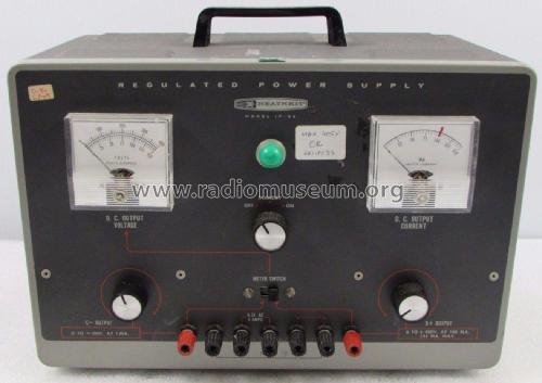
6.3 Front-Panel Quick Reference
Table 3 — 3. Front-Panel Quick Reference
| Control / indicator | Function |
|---|---|
| OFF / STANDBY / ON rotary switch | STANDBY keeps filaments warm and kills B+; ON enables B+ |
| B+ OUTPUT pot | Sets 0–400 V DC output |
| C− OUTPUT pot | Sets 0 to −100 V DC bias output |
| METER SWITCH | Selects whether the single voltmeter reads B+ (0–400 V) or C− (0–150 V range) |
| D.C. OUTPUT VOLTAGE meter | Reads whichever rail METER SWITCH selects |
| D.C. OUTPUT CURRENT meter | 0–150 mA full scale, reads B+ current only (no bias current meter) |
| Pilot light | Mains-on indicator |
| Binding posts (×7) | B+, C−, two filament (6.3 V AC), chassis ground, two COMMON |
6.4 Operating Quick-Steps
This is the condensed form of Vol 4’s operating procedure. Follow it in order every time — the STANDBY warm-up step is not optional housekeeping, it protects the 6L6 cathodes from cold-start emission stress and lets the 0A2 tubes strike cleanly before B+ is applied.
Table 4 — 4. Operating Quick-Steps
| Step | Action | Why |
|---|---|---|
| 1 | Confirm B+ OUTPUT and C− OUTPUT pots are fully counter-clockwise (minimum) before power-up | Prevents an unexpected full-scale output the instant B+ comes up |
| 2 | Set rotary switch to STANDBY, not ON | Filaments and 0A2 tubes warm/strike; B+ stays off |
| 3 | Wait ~30–60 s for tube warm-up (longer if the unit has been idle for months) | Cold cathodes + cold gas tubes give erratic early regulation |
| 4 | Set rotary switch to ON | Enables B+ through the series-pass 6L6 pair |
| 5 | Set METER SWITCH to B+, bring B+ OUTPUT up slowly while watching the voltmeter | Confirms regulation is tracking the pot, not jumping/oscillating |
| 6 | If using bias, set METER SWITCH to C−, bring C− OUTPUT to the desired negative value | Bias is current-limited internally — safe to approach directly, but still lethal voltage |
| 7 | Connect the load (breadboard/tube circuit) with the supply in STANDBY, never live | One-hand rule — see §6 |
| 8 | Bring supply to ON, monitor the D.C. OUTPUT CURRENT meter continuously while the circuit runs | No B+ current-limit exists — you are the current limiter |
| 9 | To shut down: B+/C− pots back to minimum → STANDBY → OFF, in that order | Avoids transients into the load; lets filaments cool before full power-down |
| 10 | After OFF, wait, then verify both B+ and bias rails have discharged before touching anything inside the case | Bleeder is only ~3 mA — caps stay charged for a while; see §6 |
⚠ Danger — Never adjust wiring, clip leads, or reach toward the binding posts or chassis with the supply in ON. STANDBY removes B+ but the filaments and pilot light stay lit — do not mistake STANDBY for “safe.” Full safety requires OFF and a verified discharge (§6).
6.5 Refurb Quick Order
Full detail in Vol 5. This is the sequence, not the procedure — do not skip Vol 5 the first time through a given unit.
Table 5 — 5. Refurb Quick Order
| Order | Task | Detail |
|---|---|---|
| 1 | Discharge every electrolytic manually through a resistor before touching anything inside the case, even if the unit has been unplugged for days | §6 below, Vol 5 §1 |
| 2 | Visual inspection — bulging/leaking cans, cracked wax/paper caps, discolored resistors, corroded binding posts, oxidized STANDBY switch contacts | Vol 5 §1 |
| 3 | Recap the electrolytics — main filter (70 µF/350 V → ≥100 µF/450–500 V typical replacement), plus the 40 µF and 20 µF cans, confirmed against the manual parts list before ordering | Vol 5 §3 |
| 4 | Check the ~0.047 µF coupling cap between the 6BH6 control grid and the 6L6 cathodes — a leaky example is the classic IP-32 fault and breaks both the zero-adjust and 400 V-adjust behavior | Vol 5 §4 |
| 5 | Check/replace the two selenium screen rectifiers — known wear item; restorers commonly substitute silicon diodes plus a series resistor to make up the lower forward drop | Vol 5 §3 |
| 6 | Verify pass-tube type — confirm 6L6GC (30 W dissipation) is fitted, not a metal 6L6/6L6GA/6L6GB (~19 W), which can be over-dissipated at high-current/low-output-voltage settings | Vol 5 §2, Vol 3 §2 |
| 7 | Check 0A2 reference tubes for drift/wear — they set the regulation reference point; replace if regulation or set-points read off | Vol 5 §2 |
| 8 | Re-zero the panel meter mechanically, then verify the R24 (400 kΩ, B+) and R25 (150 kΩ, C−) 1 % multiplier resistors before trusting the analog reading — a reported unit read 380 V when true output was 400 V | Vol 5 §5 |
| 9 | Re-zero and re-span the B+ regulation using the two internal trimmers in the R10–R14 divider chain against a known-good external DVM | Vol 5 §5 |
| 10 | Inspect/clean the STANDBY switch contacts and AC lead routing if hum or intermittent B+ is present | Vol 5 §4 |
| 11 | Bring up on a variac with a DVM and DMM ammeter in-line, not straight to full mains | Vol 5 §1, §6 below |
⚠ Danger — The main power transformer in this design is somewhat under-rated for the family. Do not sustain over-current conditions during bring-up or fault-finding — transformers for this unit are hard to source, and cooking the primary turns a component-level fault into an unobtainium-part problem.
6.6 HV Safety DON’Ts
These are absolute — not “best practice,” not “usually fine.” This unit generates and stores lethal voltage internally even though its front-panel output tops out at a comparatively modest 400 V. See the hub-wide HV discipline document for the full bench-safety policy this rule set inherits from.
Table 6 — 6. HV Safety DON'Ts
| DON’T | Why |
|---|---|
| Don’t assume the supply is safe because it’s unplugged or switched OFF | The bleeder draws only ~3 mA — filter caps hold a dangerous charge for a meaningful time after power-off. Manually discharge every electrolytic through a resistor before working inside. |
| Don’t work inside the case with only the internal bleeder to rely on | 3 mA through 4 × 27 kΩ is a minimum-load bleed path for regulation stability, not a rated safety-discharge circuit. Discharge actively. |
| Don’t touch the chassis or binding posts with two hands, or with one hand while grounded, above ~50 V | One-hand rule: keep one hand in a pocket or behind your back on anything above ~50 V so a shock path can’t cross your chest. |
| Don’t probe live at the raw-B+ node (≈ 600 V) or anywhere on the doubler caps | This is well past the threshold for cardiac arrest through incidental skin contact — it is not “just a jolt.” |
| Don’t exceed 100 mA continuous / 125 mA intermittent on B+ | There is no active current-limit — you are relying on the fuse and pass-tube dissipation margin, and pushing past rating risks the 6L6 pass tubes and, downstream, the under-rated power transformer. |
| Don’t load the C− (bias) output beyond 1 mA or short it deliberately | It is internally current-limited by design, but that limiting resistor/pot is a documented weak point on the sibling SP-2717A’s equivalent circuit — don’t rely on the limiter as a load-testing feature. |
| Don’t connect or disconnect a breadboard/load with the supply in ON | Always drop to STANDBY (or OFF + verified discharge) before touching leads. |
| Don’t trust the panel meter’s zero point without checking it | A 5 % low reading has been documented on this family (380 V shown for a true 400 V output) — re-zero mechanically and verify the multiplier resistors before trusting a critical measurement. |
| Don’t treat the selenium rectifiers or old electrolytics as inert curiosities | Aged selenium rectifiers can emit an acrid, mildly toxic odor if they fail; old electrolytics can vent or rupture. Handle failed originals as hazardous waste, not shop trash. |
| Don’t skip the variac/current-limited bring-up after any repair or long storage period | Bringing a 60+-year-old unit straight to full mains after a repair or years of storage is how a single bad cap becomes a shorted transformer. |
⚠ Danger — If you are new to tube-era HV work, do not use the IP-32 as your first hands-on unit without a mentor or without having read Vol 4 (Using It) and Vol 5 (Calibration & Refurbishing) in full. This is unforgiving gear built to a 1962 safety standard, not a 2020s one.
6.7 The Generational Pair — IP-32 and SP-2717A
6.7.1 The framing the scaffold got wrong
Jeff keeps the IP-32 and the SP-2717A side by side on the bench, and it is tempting to reach for the obvious story: “the IP-32 is the small one, the SP-2717A is the big one, grab whichever current rating the circuit under test needs.” That story is false. Both supplies deliver the identical 0–400 V DC @ 100 mA continuous (125 mA intermittent) B+ rating, the identical 0 to −100 V @ 1 mA bias rating, the identical four 27 kΩ / 2 W bleeder, and the identical dual-meter front panel. There is no low-current/high-current split anywhere in this family’s published specifications.
The honest framing is generational, not tiered. Both units sit on one unbroken circuit lineage that runs from the 1957 PS-4 through several later models, ending at the 1982 SP-2717A. What changed across that 20+-year span was never the output rating — it was how the regulation reference and rectification were built, as manufacturing moved from an all-tube reference to a solid-state one while the series-pass element stayed tube throughout.
6.7.2 Family lineage timeline
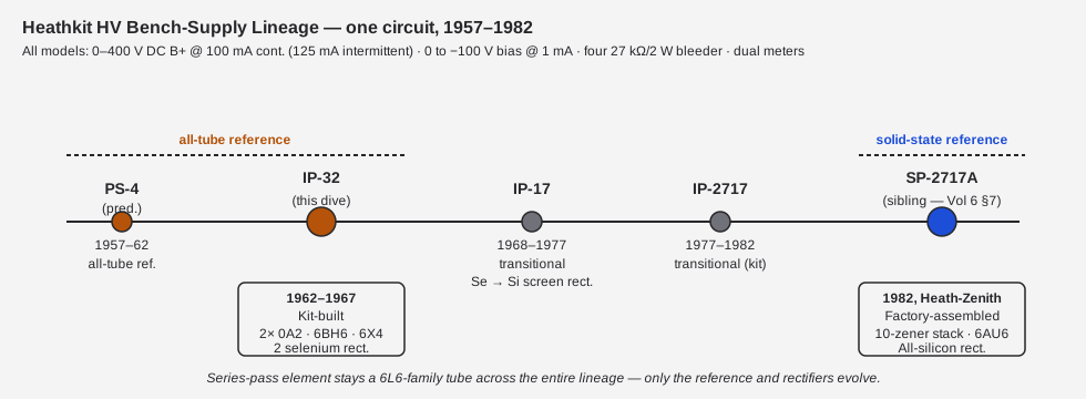
Table 7 — 7.2 Family lineage timeline
| Model | Years | Generation | Notes | detail |
|---|---|---|---|---|
| PS-4 | 1957–1962 | all-tube reference | Electrically identical circuit to the IP-32; only styling differs | Vol 1 §1 |
| IP-32 | 1962–1967 | all-tube reference | This dive’s subject. Kit-built, “Classic II” styling | Vol 1 §1 |
| IP-17 | 1968–1977 | transitional | Low-profile cabinet; selenium screen rectifiers → silicon; added 6.3/12.6 V heater option; 3-wire grounded plug | Vol 1 §1 |
| IP-2717 | 1977–1982 | transitional (kit) | Kit form of the final-generation circuit | Vol 1 §1 |
| SP-2717A | 1982 | solid-state reference | Factory-assembled Heath-Zenith relabel of IP-2717A; this pair’s sibling | — |
⚠ Danger — Do not read “solid-state reference” as “solid-state regulator.” In every model in this family, including the 1982 SP-2717A, the actual series-pass regulation element that drops raw B+ down to the set output voltage is a pair of tube pass elements (6L6 in the IP-32, 6L6GC in the SP-2717A). The lethal-voltage handling characteristics of tube gear apply to both units equally — the SP-2717A is not “safer” for having solid-state rectifiers.
6.7.3 IP-32 vs SP-2717A — the real comparison table
Table 8 — 7.3 IP-32 vs SP-2717A — the real comparison table
| Parameter | IP-32 (1962–67) | SP-2717A (1982) | Identical? | detail |
|---|---|---|---|---|
| B+ output | 0–400 V DC @ 100 mA cont. (125 mA intermittent) | 0–400 V DC @ 100 mA cont. (125 mA intermittent) | Yes | Vol 1 §2 |
| Bias (C−) output | 0 to −100 V DC @ 1 mA | 0 to −100 V DC @ 1 mA | Yes | Vol 1 §2 |
| Bleeder | four 27 kΩ / 2 W in series | four 27 kΩ / 2 W in series | Yes | Vol 3 §4 |
| Metering | Dual meter (shared voltmeter B+/C−, dedicated B+ current meter) | Dual meter (same arrangement) | Yes | Vol 3 §5 |
| B+ current limiting | None (fuse + pass-tube dissipation only) | None (fuse + pass-tube dissipation only) | Yes | Vol 2 §4 |
| Series-pass tubes | 2 × 6L6 (metal-envelope era; 6L6GC recommended for full dissipation) | 2 × 6L6GC | Same family | Vol 2 §2 |
| Control / error amp | 6BH6 | 6AU6 | No | Vol 2 §2 |
| Voltage reference | 2 × 0A2 gas VR tubes (150 V each) | 10-zener diode stack (ZD1–ZD10) | No | Vol 2 §2, Vol 3 §3 |
| B+ rectifier | Silicon diode voltage doubler | Silicon diode voltage doubler | Yes | Vol 3 §3 |
| Screen rectifier | 2 selenium rectifiers (wear item) | All silicon | No | Vol 3 §3, Vol 5 §3 |
| Bias rectifier | 6X4 tube (full-wave) | All silicon diodes | No | Vol 3 §3 |
| Filament output | 6.3 V AC @ 4 A | 6.3 V AC @ 4 A or 12.6 V AC @ 2 A (≤25 VA total) | No — SP adds a 12.6 V tap | Vol 1 §2 |
| Cabinet / styling | 13″ × 8½″ × 7″, “Classic II” dark-gray panel | Low-profile Heath-Zenith styling | No | Vol 1 §1 |
| Assembly | Kit (customer-built) | Factory-assembled | No | Vol 1 §1 |
| Era | 1962–1967 | 1982, Heath-Zenith | No | Vol 1 §1 |
6.7.4 What that table means on the bench
- Choosing between them is not a current-headroom decision. If a circuit under test needs more than 100 mA @ 400 V from B+, neither supply in this pair delivers it — reach for a different instrument entirely, or parallel loads across both with care and full understanding of what that does to each unit’s regulation loop (not covered in this dive; treat as an advanced/unverified technique).
- Choosing between them is a reference-technology and vintage-fidelity decision. The IP-32 is the correct choice when the point of the exercise is authentically reproducing a 1962-era all-tube regulator circuit, when you want the gas-tube glow of the 0A2 pair as a visual/diagnostic reference, or when working on kit-restoration technique itself. The SP-2717A is the correct choice when you want the more temperature-stable, drift-resistant zener reference and don’t need the selenium rectifiers’ era charm — or simply when the IP-32 is out of service for refurb and the SP-2717A can cover the bench.
- The 12.6 V filament tap is the SP-2717A’s one genuinely new capability. It is a real, if modest, difference: circuits built around 12.6 V heater strings (common in many post-war tube designs) can be powered directly from the SP-2717A without a separate filament transformer, where the IP-32 offers only 6.3 V.
- Fault signatures differ by generation, not by symptom severity. A 0A2 reference tube going gassy or intermittent on the IP-32 and a zener in the SP-2717A’s ZD1–ZD10 stack failing shorted from running hot against the board produce similar symptoms (regulation set-point drift or loss) through different mechanisms — see the fault table below.
6.8 Fault Quick-Reference (IP-32)
Table 9 — 8. Fault Quick-Reference (IP-32)
| Symptom | Likely cause | Check | detail |
|---|---|---|---|
| No B+ output at all, filaments/pilot lit | Rear fuse blown; STANDBY switch contacts oxidized | Fuse continuity; switch contact resistance | Vol 5 §4 |
| B+ present but won’t regulate / drifts with load | 0A2 reference tube worn or gassy | Swap known-good 0A2; check −150 V / −300 V rails | Vol 5 §2 |
| Zero-adjust or 400 V-adjust won’t hold / interacts oddly | Leaky ~0.047 µF coupling cap (6BH6 grid → 6L6 cathodes) | Replace the cap; classic IP-32 fault | Vol 5 §4 |
| B+ reads low/high vs a known-good external DVM | Panel meter zero drift or worn R24/R25 multiplier resistors | Mechanical re-zero; verify R24 (400 kΩ) / R25 (150 kΩ), both should be 1 % | Vol 5 §5 |
| Screen supply low / soft regulation at high B+ | Selenium screen rectifiers degraded (wear item) | Measure screen rail (~230 V target); consider silicon + series-R substitution | Vol 5 §3 |
| Hum on B+ or bias output | Filter electrolytics aged/dried; AC lead dress | Recap; check lead routing away from signal/output wiring | Vol 5 §3, §4 |
| Bias output won’t reach full −100 V | 6X4 rectifier weak, or R21 bias current-limit resistor drifted | Check 6X4 emission; verify R21 value | Vol 3 §3, §4 |
| 6L6 pass tube runs excessively hot | Metal 6L6/6L6GA/6L6GB fitted instead of 6L6GC at high-current/low-voltage settings | Confirm tube type; upgrade to 6L6GC | Vol 5 §2 |
| Transformer runs hot / smells | Sustained over-current condition | Check load current against 100/125 mA rating immediately; the power transformer is under-rated — don’t push it | §6 above, Vol 5 §4 |
6.9 SP-2717A Fault Quick-Reference (for the paired unit)
Because this pair lives on the bench together, a fault-finding session often needs to distinguish “which unit is actually misbehaving” fast. The SP-2717A’s zener-stack/silicon-rectifier generation fails differently from the IP-32’s tube-reference generation even though the symptoms can look alike from the front panel. This table is provided for cross-reference only — the SP-2717A’s own 6-volume dive is the authoritative source; see its Vol 5 for full detail.
Table 10 — 9. SP-2717A Fault Quick-Reference (for the paired unit)
| Symptom | IP-32 (all-tube reference) likely cause | SP-2717A (solid-state reference) likely cause |
|---|---|---|
| Regulation set-point has drifted off spec | 0A2 reference tube aged/gassy | A zener in the ZD1–ZD10 stack has drifted (less common than outright short) |
| Regulation lost entirely, output pinned or wild | 0A2 tube gone soft/dark, or pulled (pin-jumper fail-safe opens the rail) | Control-amp tube (6AU6) shorted — a documented failure mode on this generation |
| Screen supply weak at high B+ | Selenium rectifiers degraded | Silicon screen rectifiers (D1/D2) — check for opens, less prone to gradual degradation than selenium |
| Reference rail (−150 V / −300 V) shifted after a repair | 0A2 swapped for a non-matched tube | A single zener failed shorted in the stack — restorers report zeners run hot against the PCB; standing them off the board helps |
| Zero-adjust / 400-adjust interaction won’t settle | Leaky ~0.047 µF 6BH6-to-6L6-cathode coupling cap | Equivalent coupling network in the 6AU6-to-6L6GC path — verify against the SP-2717A manual before assuming parts-identical fault |
| Bias pot feels “scratchy” or burned smell near C− control | R-series bias current-limit resistor degraded | R20 (22 kΩ) current-limit resistor or the R19 (50 kΩ) C− VOLTS pot — a documented weak point if the bias output is loaded or shorted |
⚠ Danger — Do not swap tubes or reference devices between the two units to “test” a fault. The 0A2 and the zener stack are not interchangeable reference technologies, and cross-contaminating parts bins between a 1960s kit-built unit and a 1982 factory-built unit is a good way to lose track of which unit has which revision-level parts.
6.10 Recap Quick-BOM (IP-32 electrolytics)
Condensed from Vol 5 — confirm every value and voltage rating against the manual parts list before ordering; treat the “replacement” column as commonly reported practice, not a factory spec.
Table 11 — 10. Recap Quick-BOM (IP-32 electrolytics)
| Original can | Original rating | Commonly reported replacement | Location / role |
|---|---|---|---|
| Main filter | 70 µF @ 350 V | ≥100 µF @ 450–500 V | B+ doubler reservoir — sees the ~600 V raw rail, use the higher voltage rating |
| Second can | 40 µF | ≥47 µF, ≥450 V on the B+ side | Filter/reservoir |
| Third can | 20 µF | ≥22 µF, ≥450 V on the B+ side | Filter/reservoir |
Table 12 — 10. Recap Quick-BOM (IP-32 electrolytics)
| Other known recap-adjacent items | Note |
|---|---|
| ~0.047 µF coupling cap (6BH6 grid → 6L6 cathodes) | Not an electrolytic, but the single highest-value fault-clearing replacement on this unit — see §5 row 4 |
| Selenium screen rectifiers (×2) | Not electrolytics; wear item — see §5 row 5 for the silicon + series-R substitution practice |
⚠ Danger — Every cap in this table sits on or near the B+ doubler chain. Discharge before you touch, every time, with no exceptions for “I just tested it an hour ago.”
6.11 Bench Tools Checklist
What you actually want laid out before powering up either unit in this pair for service work.
Table 13 — 11. Bench Tools Checklist
| Tool | Purpose |
|---|---|
| Variac (isolated, metered) | Current-limited bring-up after any repair or extended storage |
| DVM rated for the working voltage (≥600 V DC input) | Cross-check the panel meter; the panel meter is not trustworthy until re-zeroed and verified |
| HV-rated discharge probe / resistor lead | Manual cap discharge before opening the case — never rely on the bleeder alone |
| In-line DMM or clamp meter for current | Monitoring B+ current continuously during load testing, since there is no active current-limit to protect you from a mistake |
| Insulated tools, one-hand discipline | Physical habit, not optional gear — see §6 |
| Known-good spare 6L6GC, 0A2 pair, 6BH6, 6X4 (IP-32) | Fastest fault-isolation path — substitution testing beats measurement-only diagnosis on tube gear |
| Isolation transformer (if bench is not already isolated) | Breaks the direct mains-ground bond while probing live circuits — standard tube-era bench practice |
6.12 Cross-Reference Index
Table 14 — 12. Cross-Reference Index
| Topic | Volume |
|---|---|
| What the IP-32 is, era, kit price, dimensions | Vol 1 — Overview |
| Full regulation-loop circuit theory (6L6/6BH6/0A2 interaction) | Vol 2 — How It Regulates |
| Chassis layout, all rectifiers/filters, metering detail | Vol 3 — Inside This Unit |
| Step-by-step operating procedure, HV safety in depth | Vol 4 — Using It |
| Recap BOM, calibration procedure, common failures | Vol 5 — Calibration & Refurbishing |
| This laminate + the SP-2717A comparison | Vol 6 — Cheatsheet & the Generational Pair (this volume) |
| Hub-wide HV/mains bench-safety discipline | _shared/legal_ethics.md |
| The SP-2717A’s own 6-volume dive | Heathkit SP-2717A HVPS |
Sources
- Heathkit IP-32 assembly & operation manual scans:
- archive.org — https://archive.org/details/Heathkit_IP-32_HV_Power_Supply
- vintage-radio.info — https://www.vintage-radio.info/download.php?id=212
- elektrotanya — https://elektrotanya.com/heathkit_ip-32_regulated_power_supply.pdf/download.html
- Berkeley (image-only) — https://experimentationlab.berkeley.edu/sites/default/files/NMR/Equipment/Heathkit%20IP-32_Regulated%20Power%20Supply_Manual.pdf
- Bob Eckweiler (AF6C), “Heathkit of the Month #67 — IP-32 Bench HV Power Supply,” OCARC RF newsletter, Aug 2015 — https://www.w6ze.org/Heathkit/Heathkit_067_IP32.pdf
- radiomuseum.org, IP-32 — https://www.radiomuseum.org/r/heath_regulated_power_supply_ip_5.html
- radiomuseum.org, IP-2717A (sibling) — https://www.radiomuseum.org/r/heath_regulated_hv_power_supply_ip_2717a.html
- Heath Company, “Model SP-2717A Regulated High Voltage Power Supply” manual 595-2705-02, © 1982 — https://archive.org/details/Heathkit_SP-2717A_Regulated_HV_Power_Supply
- “Heathkit Zenith SP-2717A Power Supply Restore,” Lazy Electrons, 2018-06-02 — https://lazyelectrons.wordpress.com/2018/06/02/heathkit-zenith-sp-2717a-power-supply-restore/
- IP-32 restoration write-up — https://pudar.net/heathkit-ip-32-restoration/
- Antique Radio Forums, IP-32 repair thread — https://antiqueradios.com/forums/viewtopic.php?t=440
- Chuck Penson, Heathkit Test Equipment Products (styling/production-date reference, cited via Eckweiler)