Heathkit IT-3121 Curve Tracer · Volume 1
Heathkit IT-3121 — Vol 1: What It Is & Its Place in the Heathkit Line
The affordable semiconductor curve tracer that put device fingerprinting on the hobby bench
1.1 What the IT-3121 is
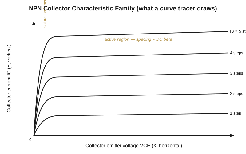
The Heathkit IT-3121 is a semiconductor curve tracer: a bench fixture that drives a device under test with a swept collector supply and a stepped base (or gate) drive, then plots the family of current-versus-voltage curves that results. Hand it a bipolar transistor, a JFET, a plain diode, a zener, or a tunnel diode, and it draws that part’s characteristic — the graphical fingerprint from which you read DC and AC beta (gain), saturation voltage, breakdown voltage, and whether the gain stays linear across the operating range. It also does the one job a go/no-go tester cannot: overlay two devices and pick matched complementary pairs for a differential front end or a push-pull output stage.
One point has to be settled up front, because it colors every design decision that follows: the IT-3121 has no CRT of its own. It is a signal source and a measurement front end, nothing more. It puts its X (horizontal) and Y (vertical) outputs onto banana jacks that feed an external oscilloscope switched to X-Y mode — X is the collector voltage, Y is the collector current, and the stack of traces you see are the base or gate steps. It was designed around an analog scope, but it drives a modern digital scope’s X-Y mode just as happily. That single choice — no display in the box — is the hinge the whole instrument turns on. It is what kept the thing small, light, and cheap, and it is the biggest single difference between the IT-3121 and the lab-grade tracers it was priced against.
The Polk Audio service-forum thread on this unit draws the contrast cleanly: the IT-3121 “connects to an oscilloscope” rather than carrying an integrated display, unlike the older vacuum-tube-era testers that packed the scope and the test set into one chassis. Splitting the display back out to a scope you already own is exactly the economy that made the instrument affordable.
1.1.1 Headline capabilities
The envelope below is drawn from Dave Erickson’s analysis of the original design (djerickson.com/curve-tracer) and the Radiomuseum catalog entry. Erickson’s own one-line summary of the instrument is worth keeping in view while reading it: “collector voltage up to +/- 200V and currents up to 1A with simple controls and lots of ranges.”
Table 1 — Headline capabilities
| Parameter | IT-3121 |
|---|---|
| Collector sweep supply | two ranges: 40 V @ up to 1 A (low-V / high-current); 200 V @ up to 200 mA (high-V / low-current) |
| Maximum collector voltage | +/-200 V (on the 200 V / 200 mA range) |
| Maximum collector current | 1 A (only on the 40 V range) |
| Base current step generator | 1-2-5 sequence, 0.002 mA — 10 mA per step (i.e. 2 uA to 10 mA/step) |
| Gate voltage step option (FETs) | 1-2-5 sequence, 0.05 V — 1 V per step |
| Display | external oscilloscope in X-Y mode — no built-in CRT |
| Internal architecture | all-analog: “18 transistors, 5 ‘741 Opamps, one TTL counter” — no microprocessor |
| Physical | 115 x 255 x 285 mm (4.5 x 10 x 11.2 in), metal case, 120/240 VAC, Heath Co., Benton Harbor, MI |
Two numbers in that table deserve a second look, because together they are the reason the instrument mattered.
First, the collector supply is genuinely two-range, and the two ranges buy different things. On the 200 V / 200 mA range you reach the full +/-200 V collector swing — enough to walk a small-signal transistor right up to its avalanche breakdown and read the knee directly. On the 40 V / 1 A range you trade voltage headroom for current, and the supply will deliver up to 1 A — enough to trace real power transistors well into their working current range rather than tickling them at milliamps. The maximum voltage and the maximum current do not happen at the same time; that is a deliberate transformer-and-switching arrangement, not a limitation to design around, and Vol 2 pulls that supply apart in detail.
Second, the base-step generator reaches all the way down to 2 uA per step. That resolution is what lets the same instrument that slams a power transistor with an amp also resolve the base current of a sensitive small-signal part. Range and resolution in one box, buildable on a kitchen table — that combination is the whole pitch.
1.2 The IT-1121 and the IT-3121: which came first
The instrument shipped under two model numbers, and getting their order right matters because it is a common trap.
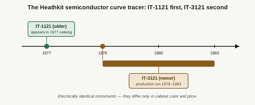
The IT-1121 is the older model. The IT-3121 is the newer one. They are the same instrument electrically — Pestinger’s Heathkit archive is blunt about it: “There were two models of this unit, the IT-1121 and the IT-3121… the only difference except for the model number was the color and the price.” Erickson says the same thing and pins the sequence: “The IT-1121 and IT-3121 are basically identical units, but the ‘3121 is a bit newer.” So there is no “derivative” here in the sense of one being a cut-down or built-up version of the other. They are one design wearing two badges. Everything true of the IT-3121 in this dive is equally true of the IT-1121, which is why Erickson titles his own project for the “IT-1121 / IT-3121” and the community uses the names interchangeably.
1.2.1 Dating it
For the IT-3121 specifically the dates are solid. Radiomuseum lists the production run as 1978-1983, built by Heath Co. of Benton Harbor, Michigan; Pestinger’s shows the IT-3121 in a 1980 catalog and lists the earlier IT-1121 as available in 1977. So “late 1970s” is a fair one-line characterization of the IT-3121, with the caveat that its life extends into the early 1980s.
The IT-1121’s first year is where the record gets soft. Pestinger’s 1977 catalog date and a Hackaday piece claiming the IT-1121 was “introduced in 1973” do not agree, and I have not found a primary source that settles it. Treat the IT-1121’s debut year as unresolved — somewhere in the early-to-mid 1970s — while treating the IT-3121 as solidly c. 1978-1983. What is not in doubt is the ordering: the 1121 is the elder, the 3121 the junior.
1.3 Why a hobbyist wanted one
Before a curve tracer, testing a transistor on a hobby bench meant a multimeter’s diode-check across two junctions, or at best a cheap in-circuit “transistor tester” that gave you one beta number and a good/bad lamp. That tells you almost nothing about how a device behaves — only, roughly, that it is not dead. A curve tracer shows the whole story on one screen at once:
- Is it alive, and which polarity? NPN versus PNP, N-channel versus P-channel — read instantly from which quadrant the curve family occupies.
- What is the gain, and is it constant? The vertical spacing between adjacent base-current curves is the DC beta at that operating point. Evenly spaced curves mean a linear, well-behaved device; curves that bunch up as you climb mean beta falling off with current, which is exactly what you need to know before you trust a part in an output stage.
- Where does it break down? Push VCE toward the +/-200 V ceiling and watch the trace bend upward — you read avalanche breakdown directly off the horizontal axis instead of guessing from a datasheet you may not have.
- Do two parts match? Overlay two devices and their fingerprints either sit on top of each other or they do not. This is the classic reason an audio builder reached for one — matching a complementary pair for a push-pull output, or a differential input pair. Matching complementary and output transistor pairs is the perennial job.
For anyone building or repairing audio gear, RF gear, or power supplies, that is a categorically different grade of information than a beta number and a lamp — and the IT-3121 delivered it for the price of a kit plus whatever scope was already on the bench.
1.4 Where it sat against the Tektronix tracers
The reference-standard semiconductor curve tracers of the era were Tektronix instruments — the earlier Tektronix 575 and its successor the Tektronix 576. These were superb, self-contained machines: a large built-in CRT with an illuminated, calibrated graticule; a collector supply reaching well past what the Heathkit offered; plug-in step generators; and safety interlocks on the high-voltage terminals. They were also large, heavy, and expensive — calibration-lab and production-line gear, not something that lived on a hobbyist’s bench or in a small TV-repair shop.
The IT-3121 is the deliberate low-cost answer to that class. It makes two big trades to hit its price:
- No CRT. You supply the scope. This removes the single most expensive subsystem of a Tek 576 — the calibrated display and its own high-voltage supply — and it is the direct reason the IT-3121 is a fraction of the size, weight, and cost. The banana-jack X-Y outputs are the whole of its “display.”
- All-analog, modest parts count. Erickson counts “18 transistors, 5 ‘741 Opamps, one TTL counter,” with “the magic in the transformer and the switching” — a straightforward 1970s analog design with no microprocessor. There are no plug-ins and no illuminated graticule; ranges are fixed on rotary switches, and you read values against the scope’s own graticule using the tracer’s per-division sensitivity settings.
What it gives up in polish, calibration, and self-contained convenience it hands back in accessibility. A small shop or a serious hobbyist could not justify a Tek 576 but could absolutely justify an IT-3121 kit standing next to the scope already on the bench. That is its place in the world: the semiconductor curve tracer for people who otherwise could not have had one at all.
1.4.1 The limits that came with the price
Two of the original’s boundaries are worth stating plainly, because they are design choices, not faults, and they shaped what came later.
- JFETs, not MOSFETs. The stock unit “doesn’t do MOSFETs, just JFETs.” The reason is the gate drive: a depletion-mode JFET wants a negative gate voltage, while an enhancement-mode MOSFET wants a positive gate voltage plus an offset the original step generator does not provide. (A later TRX Lab modification adds a small op-amp offset/polarity board inside the case to give a stock unit MOSFET-tracing capability — covered in Vol 3.)
- DC only. The original “doesn’t do AC,” so you read the DC characteristic and infer AC behavior from it.
Neither of those was a defect for the device population a 1970s hobbyist actually worked on. Both, however, became explicit targets when Dave Erickson set out to redesign the thing four decades later.
1.5 Its place in the Heathkit line, and in this collection
Within Heathkit’s “IT” instrument-tester series — tube testers, transistor testers, capacitor checkers — the IT-3121 / IT-1121 sat at the top of the device-analysis stack. It was not a go/no-go tester; it was a true characterizer, the one instrument in the line that drew the whole I-V picture instead of reducing a part to a single pass/fail verdict. It is the natural companion to Heathkit’s own scopes and signal sources, and it embodies the Heathkit thesis exactly: take a lab capability, strip it to essentials, and sell it as a kit you build yourself and therefore understand.
In this Curve Tracers category it is the vintage semiconductor anchor. It does the same job as the modern DIY VBA Curve Tracer but with 1970s parts and an external scope, and it sits opposite the tube-focused tracers in the collection — the uTracer6, the eTracer, and the uTracer NXT — which characterize vacuum tubes rather than solid-state devices. The category primer lives in the Curve Tracers Overview.
The rest of this dive follows from what is established here:
- Vol 2 opens the lid and shows how the instrument draws those curves — the stepped base/gate drive, the swept two-range collector supply, and the X-Y plot they combine into.
- Vol 3 covers servicing a 40-plus-year-old unit (Erickson’s restoration note documents replacing nine electrolytic capacitors and cleaning the switches) and then walks through Dave Erickson’s modern microcontroller redesign — which is explicitly a clone / ground-up redesign, not a restoration of a vintage chassis.
- Vol 4 is the operating and safety manual: wiring the banana jacks into a scope’s X-Y mode, running a device, reading gain / breakdown / matched pairs off the screen, and respecting the +/-200 V on the collector supply.