Heathkit IT-3121 Curve Tracer · Volume 3
Heathkit IT-3121 — Vol 3: Servicing It, and Dave Erickson’s Redesign
What breaks on a 40-year-old unit, and how Dave Erickson rebuilt the architecture with a microcontroller
3.1 What this volume is, and what it is not
Two separate jobs live in this volume, and it is worth keeping them apart because they are easy to blur together.
The first is the generic service a genuine 40-year-old IT-3121 (or its older twin, the IT-1121) needs before you trust a single reading off its banana jacks. That part is short, because the published record on servicing an original unit is short: replace the electrolytics, clean the switches, bring it up gently on a variac. There is no detailed teardown-and-repair log of a broken original in the sources — only the standard, sensible cautions any all-analog mains instrument from the late 1970s earns.
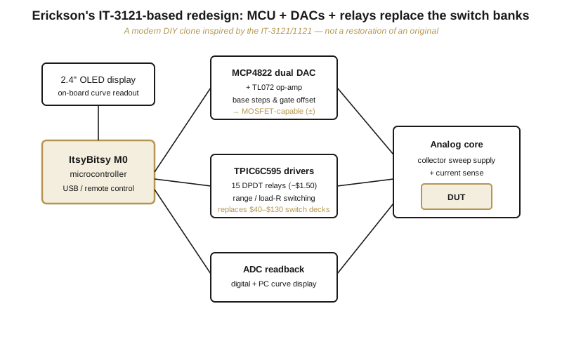
The second job is Dave Erickson’s redesign, documented at djerickson.com/curve-tracer under the title “Curve Tracer: Heathkit IT3121/1121 Based design.” That word design is load-bearing. Erickson is not restoring an original IT-3121. He is designing and building a modern DIY clone that reuses the instrument’s architecture and target specs but replaces its 1970s implementation — multi-deck rotary switches, a counter-and-transistor-DAC staircase, discrete op-amps — with a microcontroller, dual DACs, and relay banks. He opens by noting the IT-3121 has decent-for-a-DIYer specs, then reimplements it from the ground up.
So read the servicing section below as advice for a vintage chassis, and read the redesign section as Erickson’s new build. Nothing in the redesign section is a fault he found on a bench unit; it is a set of design decisions he made while replacing the old architecture. That distinction matters, and this volume is careful to hold it.
3.2 Servicing an original IT-3121
3.2.1 What is actually inside
Before you service it, know what you are looking at. Erickson, having studied the original, counts the whole active parts list at roughly 18 transistors, five 741 op-amps, and one TTL counter, with, in his words, “the magic in the transformer and the switching.” That is a genuinely spare all-analog design: a mains transformer with multiple taps feeds the collector sweep supply and the low-voltage rails; a TTL counter clocks the staircase that a small transistor-DAC network turns into the stepped base drive; five jellybean 741 op-amps do the buffering, current sensing, and X-Y conditioning; and a bank of multi-deck rotary switches selects every range, every load resistor, and every step size by hand. There is no microprocessor anywhere in it. The instrument has no CRT of its own either — it puts collector voltage on the X banana jack and collector current on the Y banana jack and lets an external oscilloscope in X-Y mode do the display (the operating detail is in Vol 4).
Knowing the parts count sets expectations for a service: this is a machine with very few active devices and a great many passive and mechanical ones, so the wear items are the passives and the switches, not the semiconductors.
3.2.2 The nine electrolytic capacitors
The single most consistent piece of service guidance for these units is a number: nine electrolytic capacitors. Erickson’s restoration note recommends replacing the nine electrolytics and cleaning the switches with contact cleaner before trusting a decades-old unit. Treat “nine” as a documented figure, not a hand-wave — that is the count called out for the recap.
Why the electrolytics first? Aluminum electrolytic capacitors age by drying out. The wet electrolyte that forms and maintains the aluminum-oxide dielectric slowly escapes through the end seal over decades, especially on parts that ran warm near the transformer and the sweep supply. As it goes, three things drift together:
- Capacitance falls. A filter cap marked, say, 100 uF can read well below its value, so the raw supply it smooths develops more ripple than the design allowed.
- ESR climbs. Equivalent series resistance — the loss term in series with the ideal capacitor — rises from milliohms toward ohms as the electrolyte degrades. High ESR both worsens ripple filtering and lets the cap heat itself under ripple current, accelerating its own decline.
- Leakage rises. A tired cap conducts a small DC leakage current through its degraded dielectric, which loads the supply and, on a reforming-gone-wrong part, can run away.
On a curve tracer the consequence is not just cosmetic hum. Ripple on the collector sweep supply rides straight onto the X axis, and ripple on the internal rails muddies the stepped base drive and the current-sense chain, so tired electrolytics show up as fat, fuzzy, or drifting traces on the external scope — exactly the readings you cannot trust. Recapping the nine electrolytics is therefore the first move, before you spend any time chasing a “bad” transistor that is really just sitting on a soft rail.
Measure the old parts as you pull them if you want the logbook discipline this project prefers: capacitance and ESR against the marked value tell you how far each had drifted, and the pattern (the hot ones near the transformer usually worst) confirms the failure mode. Replace like-for-like on voltage rating or higher, respect polarity, and prefer 105 C parts for anything living near the transformer.
3.2.3 The switches
The other classic maintenance item is mechanical. The entire user interface is multi-deck rotary/wafer switches — range, load resistor, step size, function — and after forty years their contacts oxidize. Oxidized wiper contacts add intermittent resistance in series with whatever range they select, which shows up as noisy or jumping traces, ranges that read wrong or drop out, and settings that only work if you wiggle the knob. The cure is the standard one: exercise each switch through its full rotation and clean the contacts with a proper contact cleaner (a deoxidizer, not a lubricant-only spray), working it in by rotating the switch several times so the wipers scrub the treated surfaces. Because these decks also carry the load-resistor selection in the current path, a dirty deck is not a minor annoyance — it can put a poorly-defined resistance in series with the device under test and distort the very curve you are reading.
3.2.4 Bringing an unknown unit up
Because there is a mains transformer and a collector supply that reaches into the hundreds of volts, an unknown-history IT-3121 should be brought up slowly on a variac while you watch the current draw, exactly as you would treat any mains-era gear whose filter caps may have sat unpowered for years. A slow ramp gives marginal electrolytics a chance to reform their oxide gradually rather than being slammed with full rail voltage; a sudden current spike as you raise the line tells you a cap (or worse) is shorting and to stop. This is the same discipline the B&K 1653A variac exists for on this bench.
Two safety facts frame that ramp, both carried in detail in Vol 4 but worth stating here. The collector sweep supply is two-range: 200 V at up to 200 mA on the high-voltage range, and 40 V at up to 1 A on the low-voltage/high-current range. So the maximum voltage you can find on the collector jacks is +/-200 V, and the maximum current — 1 A — exists only on the 40 V range, never at 200 V. Both numbers deserve respect: 200 V is enough to hurt you, and 1 A into a short is enough to vaporize a probe tip. Verify the reservoir capacitors are bled before you reach inside.
That is the honest extent of what the sources document for servicing a genuine unit: recap the nine electrolytics, clean the rotary switches, ramp it up carefully on a variac. Everything below is a different project entirely.
3.3 Dave Erickson’s redesign
3.3.1 The framing, again
Erickson’s write-up is a clone/redesign, not a repair log. He keeps the instrument’s concept and its target specs and rebuilds the implementation with modern parts. His stated goals: match the IT-3121’s specifications; keep a similar-or-smaller form factor; use encoders and buttons in place of the expensive rotary switches; add a digital/USB interface; add the MOSFET and AC capability the original lacked; and land around $150 in parts. Read the sections below as those decisions, attributed to him.
3.3.2 What he kept: the analog core
The redesign is a compliment to the original in that it leaves the conceptual machine intact — the same three-part idea from Vol 2:
- a collector sweep supply with a front-panel voltage set and current sensing;
- a base/gate step generator producing a staircase of drive;
- X-Y output of collector voltage versus collector current.
Erickson validated that core on a breadboard before committing to a PCB, and he did it in two distinct tests — which are worth pulling apart carefully, because the two numbers involved are easy to merge and mean different things.
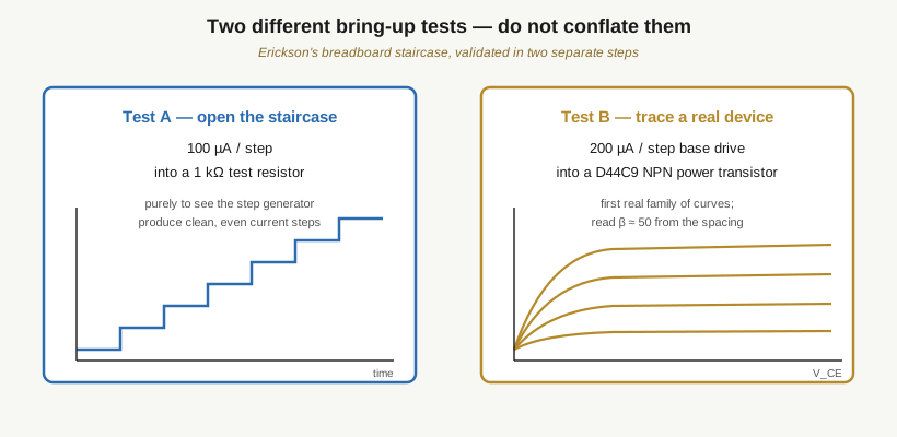
Test A — open the staircase. His first milestone was simply getting the step generator to produce a clean, even staircase of current. He drove 100 uA per step into a 1 kOhm test resistor — “baby’s first steps,” in his words. The 1 kOhm resistor is a passive dummy load; the point of the test is to watch the step generator make evenly-spaced current increments across a known resistance, not to characterize any device.
Test B — trace a real transistor. Separately, with the staircase working, he traced his first actual device: a D44C9 NPN power transistor from the 1970s, driven with a 200 uA per step base drive, from which he read a beta of about 50 by the spacing of the collector-current curves. This is a different test, a different step size, and a real semiconductor rather than a resistor.
These are not one test. There is no “200 uA/step into a 1 kOhm resistor” measurement — that phrasing wrongly welds the 200 uA/step base drive from the D44C9 test onto the 1 kOhm resistor from the staircase test. The 1 kOhm-resistor test ran at 100 uA/step; the 200 uA/step figure belongs to the D44C9. Both numbers are real and both are Erickson’s; they simply describe two different steps in his bring-up. His own verdict once both passed: the plots looked good, so it was time to lay out a real PCB. The architecture works; what he changes is how it is controlled and switched.
3.3.3 What he changed, and why
Each change targets a specific limitation of the 1970s implementation.
3.3.3.1 Multi-deck rotary switches to a microcontroller and relays
Erickson’s sharpest practical criticism of the original is the cost and complexity of its front panel. Those multi-deck rotary range switches are, today, “quite expensive, $40 up to $130” apiece, and they demand a fussy hand-wired harness — a big share of both the parts budget and the build labor sits in the switch decks. His answer is to move the switching into hardware that costs almost nothing and can be commanded in software:
- 15 DPDT relays at roughly $1.50 each carry the range and load-resistor selection that used to be knob positions. (Erickson’s own aside: “15 is kind of a lot of relays” — but at about a dollar-fifty each, a relay bank is still a fraction of one $40-$130 rotary switch.)
- TPIC6C595 shift-register drivers command the relay coils. These are power logic shift registers — you clock the desired relay pattern in serially and the open-drain outputs sink the coil currents — so a large relay bank costs the microcontroller only a few I/O pins.
- An ItsyBitsy M0 Express microcontroller sits over all of it, holding the range state and the step program in firmware.
The ranges and load-resistor selection that used to be mechanical knob positions become software-controlled relay states. That is what turns a $40-$130 switch deck into a handful of dollar-fifty relays plus a couple of shift-register chips.
3.3.3.2 A hardware step generator to dual DACs
The original’s counter-and-transistor-DAC staircase is replaced by an MCP4822 dual 12-bit DAC feeding a TL072 op-amp for the base drive. Twelve bits gives 4096 levels per DAC channel, which is ample resolution to synthesize the stepped drive digitally instead of clocking a hardware counter. More important than the tidier parts count, this makes the entire step program a matter of software: the fine base-current step selection the original did with switches — its documented 1/2/5 step sequence, 2 uA to 10 mA per step — moves into software, collapsing a bank of switches into a few lines of firmware. Step size, step count, and dwell all become variables rather than knob positions and wafer decks.
3.3.3.3 JFET-only to true MOSFET support
The original, Erickson points out, “doesn’t do MOSFETs, just JFETs.” The reason is a gate-polarity limitation. A depletion-mode JFET is normally-on and wants a negative gate voltage to pinch it off, so the original’s gate-step drive is built to sweep negative. An enhancement-mode MOSFET is normally-off and needs a positive gate voltage (plus an offset above threshold) to turn on. A single-polarity gate drive cannot serve both, so the original simply cannot trace enhancement MOSFETs.
Erickson’s two-DAC scheme solves this by driving separate positive and negative amplifier inputs to inject a programmable offset voltage, so the gate staircase can be shifted into either polarity. With the offset the same staircase can be placed in the negative region for a JFET or the positive region for a MOSFET. That is arguably the most significant functional upgrade in the whole redesign — it adds a whole device class the original could not test. (A separate, cruder hardware mod by TRX Lab reaches the same MOSFET goal on a stock unit by breadboarding an op-amp offset/polarity board inside the case; Erickson gets there natively in firmware because his gate drive is already a pair of DACs.)
3.3.3.4 Manual-only to programmable and instrumented
Because a microcontroller is now in the loop, Erickson adds capabilities the analog original never had:
- Remote control over USB. The USB link enables full remote control, so the instrument can be scripted — stepped through devices, ranges, and sweeps under program control — rather than knob-twiddled by hand.
- On-board and PC display. He adds a 2.4-inch OLED for a self-contained curve readout, and reads the measured points back with an ADC so the curves can be drawn on the OLED or streamed to a PC. This is a real departure from the original, which has no display of its own at all and depends entirely on an external X-Y scope. Erickson’s build can show its own curves; it can still drive an external scope too.
- Room to grow the envelope. He notes the original’s +/-200 V is “low for some devices, particularly tubes,” adding that “higher V would be useful — 400V good, 1KV great,” and designs so the voltage can be pushed up later. He also notes that AC testing, which the original lacks entirely, could be automated in software.
3.3.3.5 The original-versus-redesign summary
Table 1 — The original-versus-redesign summary
| Aspect | Original IT-3121 | Erickson’s redesign |
|---|---|---|
| Range / load selection | multi-deck rotary switches ($40-$130 each) | 15 DPDT relays (~$1.50 each) via TPIC6C595 shift registers |
| Control brain | none — all analog (18 transistors, 5x 741, 1 TTL counter) | ItsyBitsy M0 Express microcontroller, USB |
| Base / gate drive | TTL counter + transistor DAC staircase | MCP4822 dual 12-bit DAC + TL072 op-amp |
| FET support | JFET only (single gate polarity) | JFET and MOSFET (programmable +/- gate offset) |
| Display | external X-Y scope only | 2.4” OLED + PC display + external scope |
| Measurement | analog only | ADC readback of curve points |
| AC test | no | planned, in software |
| Voltage ceiling | +/-200 V (200 mA) / 40 V (1 A) | +/-200 V now; designed to grow toward 400 V-1 kV |
| Target parts cost | (kit-era) | ~$150 |
3.3.4 The lesson the redesign teaches
Erickson’s project is the best kind of tribute: it proves the IT-3121’s analog core is sound. A good two-range collector sweep supply — 200 V at 200 mA and 40 V at 1 A — and a clean stepped base/gate generator are still the right way to trace a device in 2020s parts, just as they were in 1978. What his redesign exposes is precisely which parts of the implementation were artifacts of 1978’s parts and economics rather than of the method itself: the expensive, hard-to-source multi-deck rotary switches; the single-polarity gate drive that shut out MOSFETs; and the total dependence on an external scope for any picture at all.
Swap the switch banks for fifteen dollar-fifty relays under shift registers, the discrete counter-DAC staircase for an MCP4822 driven in firmware, and the knobs for an ItsyBitsy microcontroller with a USB port, and the same instrument becomes cheaper to build, able to trace MOSFETs it never could, controllable from a laptop, and capable of showing its own curves on a 2.4-inch OLED — all while keeping the analog heart that made the original worth cloning. Vol 4 returns to the original hardware and puts it to work: wiring it to a scope in X-Y, running a device, and reading gain, breakdown, and matched pairs off the curves — with the +/-200 V and 1 A limits firmly in mind.