Heathkit SP-2717A HVPS · Volume 1
Heathkit SP-2717A — Vol 1: Overview — A Regulated HV Bench Supply for Tube Work
Dial up 400 V of clean, regulated B+ from a bench box built in 1982 so a breadboarded tube stage never has to wait on its own power supply.
1.1 Why this box earns bench space
Every tube circuit needs three different supply rails before it does anything useful: a plate (B+) supply at whatever the design calls for, up to several hundred volts; a filament/heater supply, almost always a low-voltage AC winding; and, for most linear stages, a negative grid-bias supply to set the operating point. Building all three from scratch — a power transformer, a rectifier, a filter, and (if the circuit needs it) active regulation — is itself a nontrivial design exercise, and it’s prerequisite work that has nothing to do with the actual circuit under test. A preamp stage, an audio output stage, an RF oscillator: none of them can be breadboarded and evaluated until their power rails exist.
The Heathkit SP-2717A Regulated High Voltage Power Supply exists to remove that prerequisite. It is a single bench instrument that supplies all three rails simultaneously, regulated, metered, and adjustable from the front panel:
⚠ Danger — this instrument generates lethal high voltage. The B+ doubler capacitors sit at roughly +600 V raw, unregulated, before the series-pass regulator drops it to whatever the front panel is set to. There is no active current limit on the B+ output — only the mains fuse and the pass tubes’ own dissipation limit stand between a mistake and a sustained high-voltage, moderate-current path through a body. Treat every internal node as live until proven dead with a meter, discharge the filter capacitors before reaching into the chassis, and read Vol 4 §4 and the hub’s
_shared/legal_ethics.mdbefore powering this unit up for the first time. One-hand rule above ~50 V, always.
With this supply sitting next to a breadboard, testing an unfamiliar tube circuit stops being a power-electronics project and goes back to being a circuit-design exercise: dial in the plate voltage the datasheet calls for, dial in the bias the load line needs, apply filament power, and start measuring the circuit, not the supply.
1.1.1 The historical role: Heath’s “instrument power” line
Heath sold this exact category of product — a dedicated, regulated HV bench supply, sold separately from any receiver, amplifier, or test instrument it might power — for over three decades, under the model prefixes PS (Power Supply) and later IP (Instrument Power). That naming is a tell about the intended customer: not a hobbyist building one specific radio, but anyone doing recurring bench work on tube circuits generally — kit-builders bringing up a newly assembled receiver for the first time, service techs troubleshooting someone else’s amplifier, and (per §5 below) eventually engineers and hobbyists breadboarding original designs. A dedicated bench HV supply amortizes the cost of a good regulator, a good pair of meters, and proper protection circuitry across every tube project that comes after it, rather than re-paying that cost inside each individual chassis. That’s the same economic logic behind any general-purpose bench instrument — a scope, a DMM, a signal generator — applied to the one supply rail that tube circuits uniquely need and solid-state circuits mostly don’t: several hundred regulated volts.
1.2 What it is, in one paragraph
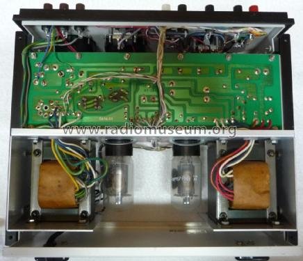
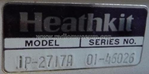
The Model SP-2717A is a Heath Company bench instrument — printed on its own manual cover and front panel as “SP-2717A,” part number 595-2705-02, copyright 1982, published by Heath Company, Benton Harbor, Michigan — Heath’s decades-long home base. By 1982 Heath had been owned by Zenith since 1979, so this unit is correctly described as a Heath-Zenith-era product — restorers commonly write it “Heathkit/Zenith SP-2717A.” It delivers three regulated/controlled outputs simultaneously — a 0–400 V DC B+ supply, a 6.3 V or 12.6 V AC filament supply, and a 0 to −100 V DC bias supply — read on two front-panel meters, with a STANDBY mode that keeps filaments warm while B+ and bias sit at zero. It is a hybrid instrument: the series-pass regulating element is a pair of vacuum tubes, but the rectifiers and the voltage reference behind them are solid-state. §3 below unpacks each output; §5 places the unit in its 32-year circuit lineage; Vol 2 covers exactly how the regulation loop holds the output constant.
1.2.1 A note on the model name
Do not “correct” SP-2717A to IP-2717A — both names describe the same electrical product, and the SP-2717A’s own manual, front panel, and part number all print SP. The best-supported explanation is that SP denotes the factory-assembled version and IP-2717 denotes the kit: the SP-2717A manual’s table of contents runs Introduction → Specifications → Operation → Circuit Description → Recalibration → Parts List, with no step-by-step assembly section — the hallmark of a Heath assembled-product manual rather than a kit manual, and at least one period sales listing explicitly describes the SP-2717A as “a factory built unit, not a Kit.” Radiomuseum happens to catalog this same circuit under the name IP-2717A; its listed tube complement (two 6L6GC, one 6AU6) and outputs match the SP-2717A manual exactly, confirming it as the identical electrical product under a different catalog label rather than a different design. Vol 3 §1 and Vol 6 revisit this naming question with the full parts-list cross-check.
1.3 The three outputs
The SP-2717A’s whole reason for existing is that it produces all three tube-circuit supply rails at once, each independently controllable from the front panel, each rated to genuinely useful levels for breadboard work. None of the three shares a control with another — set the plate voltage, the bias voltage, and the filament tap independently and they hold.
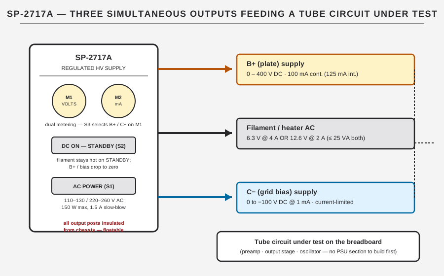
Table 1 — The three outputs
| Output | Range | Current | Notes |
|---|---|---|---|
| B+ (plate) | 0–400 V DC, regulated | 100 mA cont. / 125 mA int. | no active current limit — protected only by mains fuse + pass-tube dissipation |
| C− (bias) | 0 to −100 V DC | 1 mA | current-limited via series resistor; special-taper control for fine low-bias adjustment |
| Filament (AC) | 6.3 V or 12.6 V AC | 4 A or 2 A | both taps usable together if combined power ≤ 25 VA |
| Metering | M1: 0–400/0–150 V DC (±3%) · M2: 0–150 mA (±2%) | — | S3 switches M1 between B+ and C−; M2 fixed in the B+ return |
1.3.1 B+ (plate) supply
Table 2 — B+ (plate) supply
| Parameter | Rating |
|---|---|
| Voltage | 0 to 400 V DC, regulated, continuously adjustable from the front panel |
| Current | 0 to 100 mA continuous; 125 mA intermittent |
| Load regulation | output varies < 1% from no load to full load, over the 100–400 V DC range |
| Line regulation | output varies < ±1% for a ±10% change in the 120 V or 240 V AC mains |
| Ripple/noise | < 10 mV RMS ripple, jitter, and noise |
| Output impedance | < 10 Ω, DC to 1 MHz |
This is the rail that runs the plate (and, through a separate screen-grid tap internal to the supply itself, keeps the series-pass tubes’ own screens fed — see Vol 2). It is regulated in the classic series-pass sense: a control tube compares a sample of the output against a fixed reference and adjusts a pair of pass tubes to hold the output steady against both load changes and line changes. There is no active current-limit or foldback circuit on the B+ output — the 100 mA/125 mA rating is a dissipation rating for the pass tubes, backed only by the mains fuse. Push the B+ output hard into an overload or a short and the protection you’re relying on is the fuse blowing, not a graceful current limit. See Vol 2 §3 and Vol 4 §3 for what that means operationally.
1.3.2 C− (bias) supply
Table 3 — C− (bias) supply
| Parameter | Rating |
|---|---|
| Voltage | 0 to −100 V DC, negative, continuously adjustable |
| Current | 1 mA |
| Adjustment | dedicated C− VOLTS front-panel control with a special non-linear (“special taper”) action for fine control at low bias values |
| Protection | current-limited / short-circuit protected via a series resistor in the bias line |
This rail sets the grid bias for whatever stage is under test — a Class A audio stage, a cathode-follower, an RF amplifier biased for linearity. Unlike B+, the bias output genuinely is current-limited: a resistor in series with the C− output caps the fault current if the bias line is shorted or overloaded, specifically so an accidental short doesn’t propagate damage back through the regulator. That said, the 1 mA rating is modest — restorers note that sustained loading of the bias output risks burning the C− VOLTS control pot itself, so treat 1 mA as a real ceiling, not a suggestion.
1.3.3 Filament / AC supply
Table 4 — Filament / AC supply
| Parameter | Rating |
|---|---|
| 6.3 V tap | 6.3 V AC @ 4 A |
| 12.6 V tap | 12.6 V AC @ 2 A |
| Simultaneous draw | both taps may be used at once, provided total power ≤ 25 VA |
This is a straight AC filament winding — no rectification, no regulation — sized for the two most common tube-heater voltages so the same supply serves 6.3 V-heater tubes (the vast majority of receiving tubes) and 12.6 V-heater tubes (series-string designs, some TV-set-derived types) without a jumper change. The 25 VA combined ceiling matters if a breadboard genuinely needs both taps loaded at once — check the sum of the two heater currents against it.
1.3.4 Output posts and floating outputs
All output binding posts — Common and + (B+), Common and − (C−), 6.3 VAC @ 4 A, 12.6 VAC @ 2 A, and Chassis Ground — are electrically insulated from chassis. That is a deliberate design choice, not an oversight: it means B+ and C− can each be floated relative to whichever “common” point the breadboarded circuit actually uses, rather than being forced to reference the SP-2717A’s own chassis. For a circuit that needs its cathode, not chassis, held at the supply’s common, that flexibility matters.
⚠ Danger — “insulated from chassis” is a design fact, not a safety fact. A floated B+ output can put lethal voltage between two points neither of which is grounded — including a point that looks harmless because it isn’t the chassis. Confirm with a meter which node is actually at what potential before touching anything. See Vol 4 §4.
1.4 Dual metering and STANDBY
The SP-2717A carries two panel meters, consistent with the whole PS/IP/SP family lineage:
Table 5 — The SP-2717A carries two panel meters, consistent with the whole PS/IP/SP family lineage
| Meter | Range | Accuracy | Function |
|---|---|---|---|
| M1 (voltmeter) | dual scale, 0–400 V and 0–150 V DC | ±3% of full scale | reads either B+ or C− volts, selected by the front-panel VOLTMETER switch (S3) |
| M2 (milliammeter) | 0–150 mA | ±2% of full scale | permanently wired in the B+ cathode return — reads B+ load current directly |
M1 is a shared meter: because B+ can run to 400 V and C− only to −100 V, one dual-scale movement covers both jobs, with the S3 switch physically routing the meter between them. A colored indicator lamp tells you at a glance which one you’re looking at — red for B+, amber for C− — driven off the filament transformer independent of the DC being monitored, so the lamp works even in STANDBY. M2 has only one job: it sits in the B+ return path and reads plate current continuously, which is exactly the number you need when finding a tube’s operating point or checking against a datasheet’s rated plate dissipation.
STANDBY is the second panel switch beyond the AC POWER switch: DC ON–STANDBY (S2). Selecting STANDBY drops B+ and bias to zero while leaving the filament transformer running — because the filament and B+/screen supplies come off separate transformers (T2 for filaments, T1 for the high-voltage and screen windings), the tube heaters in the circuit under test (and in the supply’s own regulator) can stay at operating temperature between tests without a full re-warm-up cycle. Practically: park a breadboard on STANDBY between measurements, keep the tubes warm and stable, and only switch to DC ON when you’re ready to apply plate voltage — which is also the moment the lethal-voltage warning above stops being abstract.
1.4.1 Why regulated HV specifically matters for breadboarding
It would be simpler to build a raw rectifier-and-filter B+ source with no active regulation at all — a transformer, a bridge or doubler, a capacitor, done. The reason the SP-2717A (and its whole lineage) bothers with active series-pass regulation instead is that an unregulated supply’s output voltage moves with both its load and its line, and a breadboard is exactly the environment where both of those move constantly. Swap in a different tube, change a cathode resistor, add a second stage — the B+ current draw changes, and on an unregulated supply so does the B+ voltage, silently invalidating whatever load-line point you thought you were testing at. The SP-2717A’s < 1% load regulation from no load to full load and < ±1% line regulation for a ±10% mains swing mean the number on M1 stays trustworthy as the breadboard itself changes underneath it — a property a raw supply structurally cannot offer, and one that matters more, not less, in an experimental setting where the load is deliberately being varied.
1.5 The lineage: one circuit, refined for 32 years
The SP-2717A is not a standalone design. It is the 1982 endpoint of an unbroken Heath circuit lineage that traces back to the PS-1 in 1950 — a 32-year family — with the fundamental circuit architecture itself originating in the PS-4 in 1957 and refined through four further generations, each keeping the same fundamental architecture — a tube series-pass regulator delivering roughly 0–400 V B+ at roughly 100 mA — while modernizing the supporting circuitry generation by generation.
Table 6 — The lineage: one circuit, refined for 32 years
| Generation | Years | Reference | Rectification | Notes |
|---|---|---|---|---|
| PS-1 | 1950 | — | — | earliest of the line |
| PS-2 | 1952 | — | — | |
| PS-3 | 1954 | — | — | |
| PS-4 | 1957 | — | — | the circuit origin this whole family descends from |
| IP-32 | 1962–1967 | 2× 0A2 VR tubes | 6 silicon diodes + 2 selenium rectifiers (bias: 6X4 tube) | all-tube reference generation — the sibling dive covers it in full |
| IP-17 | 1968–1977 | — | — | |
| IP-2717 | 1977–1982 | tube (6BH6 control, 0A2, 6X4) | — | the kit version of this generation |
| SP-2717A | 1982+ | 10× zener diode stack (ZD1–ZD10) | all silicon (voltage doubler D3–D6; bias D7–D9) | solid-state-reference generation, this unit; factory-assembled |
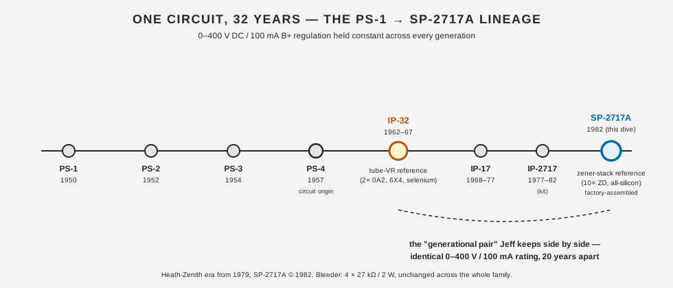
The load-bearing point, worth stating plainly because it corrects a common assumption about this pair: the SP-2717A is not a higher-current sibling of the IP-32. Both units are rated 0–400 V DC at 100 mA continuous (125 mA intermittent) B+, identically. Both deliver 0 to −100 V bias at 1 mA, identically. Both use a four-resistor, 27 kΩ/2 W-each bleeder across the same node in the circuit, identically — unchanged across the whole family. If Jeff keeps the IP-32 and the SP-2717A side by side on the bench, it is genuinely a same-rating pair, not a low-current/high-current pair. What actually changed between them, over those twenty years, is how the regulation is implemented — not how much it can deliver:
- The IP-32 (1962–67) is the all-tube-reference generation: two 6L6 series-pass tubes driven by a 6BH6 control amplifier, referenced against two 0A2 gas voltage-regulator tubes, rectified by six silicon diodes plus two selenium rectifiers, with a 6X4 tube rectifying the bias line.
- The SP-2717A (1982) is the solid-state-reference generation: two 6L6GC series-pass tubes (the same beam-power tube family, in its later “GC” revision) driven by a 6AU6 control amplifier, referenced against a stack of ten zener diodes (ZD1–ZD10) in place of the 0A2 tubes, with all rectification done in silicon — no 6X4, no selenium anywhere in the circuit.
Both generations keep the vacuum-tube series-pass element throughout — that part of the design never went solid-state, even in 1982. What modernized was the reference and the rectifiers around it. Vol 2 covers exactly how the SP-2717A’s zener stack and 6AU6 control loop hold regulation; Vol 6 §2 lays the full component-by-component IP-32/SP-2717A comparison table side by side, including the meters, bleeder, and filament differences. The Heathkit IP-32 dive covers the earlier generation’s own circuit in full.
1.5.1 A worked example: bringing up a small audio stage
Concretely, here is what “breadboard without building the power-supply section first” looks like on this bench. Say the circuit under test is a small single-ended Class A audio output stage built around a 6V6 beam-power tube, driven by a 12AX7 triode gain stage — a textbook combination and a reasonable stand-in for “an unfamiliar tube circuit” in general:
- Filament first, on STANDBY. Connect the 6.3 V AC tap to both tubes’ heaters (a 12AX7 and a 6V6 are both 6.3 V-heater types, so the 12.6 V tap isn’t needed here). With S2 on STANDBY, B+ and bias are both at zero, so the heaters can come up to temperature — several minutes, per the manual’s own recalibration procedure — with no HV anywhere on the breadboard yet.
- Set bias before B+. Datasheet load-line work for a 6V6 in this kind of stage typically calls for a grid bias in the range of several tens of negative volts, well inside the SP-2717A’s 0 to −100 V range at 1 mA — comfortably enough current for a single grid-bias network. Dial the C− VOLTS control to the target value with M1 switched (via S3) to read C−, before switching to DC ON, so the stage never sees an undefined transient bias.
- Bring up B+ under load. Switch S2 to DC ON and bring the B+ VOLTS control up toward the datasheet’s plate-voltage target — commonly in the 250–350 V region for a 6V6 stage like this, well within the SP-2717A’s 400 V ceiling. Watch M2 (the milliammeter) as the plate current settles; it’s reading the same B+ cathode-return current the tube itself is drawing, so it’s a direct check against the datasheet’s rated plate dissipation without needing a separate current probe.
- Iterate, not fumble. Because B+, bias, and filament are all independently set and independently metered, changing one variable — say, moving the bias point to explore a different operating class — doesn’t require re-deriving the other two. That decoupling is the entire point of using a dedicated supply instead of a purpose-built one: the supply’s controls map directly onto the load-line variables the circuit design already cares about.
Vol 4 walks the equivalent procedure with full step-by-step detail, control-by-control, plus the mandatory safety checks at every stage; this is the shape of the workflow, not the complete procedure.
1.5.2 Mains input and power budget
Table 7 — Mains input and power budget
| Parameter | Rating |
|---|---|
| Mains voltage | 110–130 V AC or 220–260 V AC, wired-selectable (see manual for the 240 V connection change), 50/60 Hz |
| Maximum power draw | 150 W |
| Fuse (110–130 V operation) | 1.5 A slow-blow |
| Fuse (220–260 V operation) | 1.0 A (recommended) |
| Front-panel switches | AC POWER (S1) — mains on/off; DC ON–STANDBY (S2) — see below |
150 W maximum covers all three outputs simultaneously at their combined worst case, plus the supply’s own housekeeping (screen supply, control-amplifier plate/screen power, meter lamps). The 1.5 A slow-blow mains fuse is also, per §3 above, the only protection standing behind the B+ output on a sustained overload — it is sized for normal operation, not as a fast-acting current limiter, so don’t expect it to save a shorted breadboard from damage before the pass tubes see real stress.
1.6 What’s in the rest of this dive
This overview sets the frame; the remaining five volumes go deep on each piece:
- Vol 2 — How It Regulates: The Series-Pass Tube Regulator — the full feedback loop: how the 6AU6 control amplifier, the zener reference stack, and the two 6L6GC pass tubes work together to hold B+ constant against load and line changes, run as pentodes specifically for their low-dropout headroom.
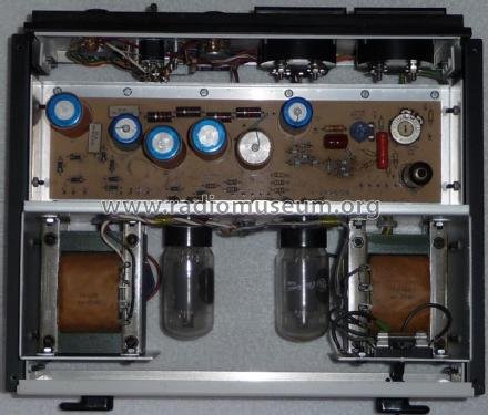
- Vol 3 — Inside This Unit: Hardware, Devices, Outputs & Metering — the physical build: transformers, the doubler and its 68 µF reservoir caps, the screen supply, the bias/reference supply, the meters, and the full tube/diode complement with part numbers.
- Vol 4 — Using It: Operating Procedure & HV Safety — power-up sequence, STANDBY discipline, setting B+ and bias for a real breadboard, and the full HV-safety procedure — this is the volume to read before ever switching S2 to DC ON.
- Vol 5 — Calibration & Refurbishing — the two-pot ZERO VOLTAGE / 400 VOLT ADJUST recalibration procedure, the recap list (which electrolytics, which voltage ratings), and the documented failure modes: a shorted 6AU6, shorted zeners running hot against the PCB, and the rest.
- Vol 6 — Cheatsheet & the Generational Pair — quick-reference tables, the full IP-32/SP-2717A component comparison, and a one-page pre-flight checklist for the bench.
Sources
- Heath Company, Model SP-2717A Regulated High Voltage Power Supply, operation/service manual 595-2705-02, © 1982 (Benton Harbor, Michigan) — Specifications, Circuit Description, Recalibration, and Parts List. Internet Archive: https://archive.org/details/Heathkit_SP-2717A_Regulated_HV_Power_Supply
- Bob Eckweiler (AF6C), “Heathkit of the Month #67 — IP-32 Bench HV Power Supply,” Orange County Amateur Radio Club, © 2015 — family lineage (PS-1 through SP-2717A), the IP-32 circuit, and the four-resistor 27 kΩ/2 W bleeder. https://www.w6ze.org/Heathkit/Heathkit_067_IP32.pdf
- Radiomuseum, “Heath (Heathkit) Regulated HV Power Supply IP-2717A”: https://www.radiomuseum.org/r/heath_regulated_hv_power_supply_ip_2717a.html
- Radiomuseum, “Heath (Heathkit) Regulated High Voltage Power Supply IP-2717”: https://www.radiomuseum.org/r/heath_regulated_high_voltage_p.html
- “Heathkit Zenith SP-2717A Power Supply Restore,” Lazy Electrons, 2018-06-02 — https://lazyelectrons.wordpress.com/2018/06/02/heathkit-zenith-sp-2717a-power-supply-restore/