Heathkit SP-2717A HVPS · Volume 4
Heathkit SP-2717A — Vol 4: Using It — Operating Procedure & HV Safety
A step-by-step operator's reference for a supply that can put 600 V raw on a filter cap and give you exactly one mistake to learn from.
4.1 Scope of This Volume
This volume is the bench-operator’s manual: what to check before power-on, how to bring the SP-2717A up safely, how to set B+ and bias, how to read what the two meters are actually telling you, how the floating output posts let you wire the supply as a positive source, a negative source, or a stacked pair referenced to a chosen common, and — because this is a lethal-voltage instrument with no B+ current-limit — a safety section that is not optional reading. Vol 1 covers what this instrument is and why it exists on the bench; Vol 2 covers how the series-pass regulator works internally; Vol 3 catalogs the hardware, devices, and controls this volume assumes you already recognize; Vol 5 covers calibration and refurbishing (the board-level R10/R14 adjustments are mentioned here only insofar as an operator needs to know they exist — the full procedure lives there). Vol 6 is the cheatsheet.
Everything in this volume assumes the unit is electrically sound and in calibration. If you are bringing up a supply that has sat in a closet for twenty years, read Vol 5 first and reform the electrolytics on a Variac before you ever follow the power-on sequence below at full mains.
Quick-reference — front-panel controls and posts (detail in the sections cited):
Table 1 — Quick-reference — front-panel controls and posts (detail in the sections cited)
| Control / post | Designation | Function | Detail |
|---|---|---|---|
| AC POWER switch | S1 (60-24) | Mains on/off — energizes T2 (filament) and T1 (HV) primaries | § 3 |
| DC ON–STANDBY switch | S2 (61-9) | Selects whether the regulated DC outputs are live (DC ON) or killed while filaments stay hot (STANDBY) | § 4 |
| VOLTMETER switch | S3 | Selects whether M1 displays B+ or C− | § 6.1 |
| B+ VOLTS control | R12, 500 kΩ | Sets B+ output, 0–400 V DC | § 5.1 |
| C− VOLTS control | R19, 50 kΩ, special taper | Sets bias output, 0 to −100 V DC | § 5.2 |
| M1 (voltmeter) | part 407-123 | Dual-scale 0–400 V / 0–150 V DC, ±3% FS — reads whichever output S3 selects | § 6.1 |
| M2 (milliammeter) | part 407-124 | 0–150 mA, ±2% FS — B+ load current, always live | § 6.2 |
| Common post | — | Floating reference; ties to whatever DUT node the operator chooses | § 7 |
| + post (B+) | — | 0–400 V DC, 100 mA cont. / 125 mA intermittent | § 5.1, § 7 |
| − post (C−) | — | 0 to −100 V DC, 1 mA max | § 5.2, § 7 |
| 6.3 VAC post | — | 4 A max (≤25 VA combined with 12.6 V post) | § 8 |
| 12.6 VAC post | — | 2 A max (≤25 VA combined with 6.3 V post) | § 8 |
| Chassis Ground post | — | Bonded to case + mains ground — NOT part of the floating signal path | § 7 |
⚠ Danger — read this volume before you touch the panel. The SP-2717A regulates up to 400 V DC and derives that output from roughly 600 V raw across a pair of 68 µF doubler capacitors that stay charged after the unit is switched off. There is no active current-limit on the B+ output — only a mains fuse and the pass tubes’ own dissipation limit stand between a mistake and a destroyed supply, or worse, a destroyed hand. Cross-reference
_shared/legal_ethics.mdfor the hub-wide HV bench discipline before proceeding, and treat § 10 below as load-bearing, not decorative.
4.2 Pre-Power Inspection
Do this every session, not just the first time. A five-minute look-over is cheap; a hand across a charged 600 V node is not.
- Visual check of the case and panel. No cracked insulation on the line cord, no bent or missing binding posts, no visible scorching around the fuse holder or the ventilation louvers on the case top (directly over the pass tubes — see Vol 3 § 2 for the internal layout). If Jeff’s unit has been moved or stored since the last session, re-check here rather than assuming yesterday’s inspection still holds.
- Output posts unloaded, or loaded with a known device. Before applying power, know what — if anything — is clipped to the B+, C−, filament, and Common posts. Never bring the supply up “to see what happens” with an unknown DUT already wired across the HV posts.
- VOLTS controls at their safe starting position. Both the B+ VOLTS control (R12) and the C− VOLTS control (R19) should be turned fully counter-clockwise before power-on — B+ VOLTS CCW is 0 V output; C− VOLTS CCW is 0 V output. Starting from zero and bringing the output up under observation is the entire discipline of this volume; starting from “wherever the knob was left” is how a DUT sees a surprise 380 V.
- DC ON–STANDBY switch (S2) at STANDBY. Don’t let the B+ rail come up before you’re at the panel watching the meter. STANDBY is covered fully in § 4.
- AC POWER switch (S1) OFF. Confirm before plugging in.
- Mains voltage and fuse match. The SP-2717A is wired-selectable for 110–130 V or 220–260 V, 50/60 Hz AC, 150 W maximum. Confirm the internal mains-voltage wiring matches the outlet you’re about to use — this is a rear/internal strap, not a front-panel switch, so it’s easy to forget it was last set for a different line voltage. The fuse should be 1.5 A slow-blow for 110–130 VAC operation, or 1.0 A for 220–260 VAC operation. A fuse of the wrong rating is not a minor detail on a supply whose only B+ fault protection is that fuse (§ 10.4).
- Ground/Common posts identified. Locate Chassis Ground and the Common post on the panel before you need them under time pressure. They are not the same node — Common is one of the insulated, floatable output posts; Chassis Ground is bonded to the case and the mains safety ground. § 7 covers the distinction and why it matters.
- If this is a first power-up after storage or a repair, do it through a Variac with a current-limiting bulb in line, watching for smoke, smell, or an unusually fast fuse-warm mA reading, per Vol 5. Do not skip straight to full-mains, full-voltage operation on a supply of unknown history.
4.3 Power-On Sequence and Warm-Up
4.3.1 Why warm-up matters here specifically
The series-pass regulator (Vol 2 § 1–2) is built around two indirectly-heated tubes — the 6L6GC pass tubes (V2, V3) and the 6AU6 control amplifier (V1) (Vol 3 § 1). None of the three can control anything until their cathodes reach operating temperature; a cold 6AU6 cannot hold the loop in regulation, and cold 6L6GCs are not a reliable series-pass element. The recalibration procedure in the manual explicitly directs “warm up filaments several minutes, then DC ON” — that instruction generalizes to every normal power-up, not just calibration sessions.
4.3.2 Sequence
Table 2 — Sequence
| Step | Action | What you should see |
|---|---|---|
| 1 | B+ VOLTS and C− VOLTS controls: confirm fully CCW. | Both pots at their zero-output stop. |
| 2 | VOLTMETER switch (S3) to B+. | Not load-bearing for warm-up itself, but puts the meter where you’ll want it next. |
| 3 | DC ON–STANDBY switch (S2): confirm STANDBY. | — |
| 4 | AC POWER switch (S1): ON. | Filament transformer T2 energizes; after a few seconds the tube heaters glow visible orange through the ventilation louvers. Panel/meter-lamp circuitry (fed from T2’s reference point “A” per Vol 3 § 4) comes alive — you should see the meter’s colored indicator lamp light. |
| 5 | Let the tubes warm up — several minutes. | Filaments at full glow, steady. This is time for cathode emission to stabilize before B+ is asked to do anything. Use this time to finish the DUT hookup (§ 7–9) if you haven’t already, or just wait — do not rush this step to save ninety seconds. |
| 6 | DC ON–STANDBY switch (S2): DC ON. | The B+ and bias rails come alive. With the VOLTS controls still at CCW/zero, M1 should read at or near 0 V. If it doesn’t, see the recalibration note below. |
| 7 | Bring up B+ and/or bias per § 5, watching the meters continuously as you turn each control. | — |
⚠ Danger — Step 6 is the moment the HV rail comes alive. Do not have your hands, a probe, or any part of your body near the output posts, the chassis interior, or exposed wiring when you move S2 from STANDBY to DC ON. Confirm the VOLTS controls are at zero before this step, not after.
If M1 does not settle near 0 V with both VOLTS controls fully CCW after warm-up, the unit needs the ZERO VOLTAGE ADJUST (R10) cal pot touched — that is a Vol 5 procedure, not a per-session workaround. Don’t compensate for an out-of-cal zero point by eyeballing an offset; fix the zero.
4.4 The STANDBY Function
The DC ON–STANDBY switch (S2) is the single most useful control on this panel for a bench that gets used repeatedly through a session, and it exists because Heath gave the filament and high-voltage sections separate transformers — T2 (filament, part 54-184) and T1 (power/HV, part 54-185). STANDBY switches only the DC output stage; T2 stays energized and the tube heaters stay hot the entire time the AC POWER switch is ON, regardless of the STANDBY/DC ON position.
What STANDBY does:
- Kills the B+ and bias DC outputs — no volts at the + or − posts, meter reads 0 V regardless of VOLTS control positions.
- Leaves the filament transformer (T2) running — the 6AU6 and both 6L6GC tubes stay hot.
- Leaves the 6.3 V / 12.6 V AC filament output posts live, since those come off T2 directly (§ 8).
What STANDBY is for:
- Repositioning or reconnecting the DUT without a cold-tube warm-up cycle. Swap a component, move a clip lead, or change a bias-string tap with the HV rail dead but the tubes ready to regulate the instant you flip back to DC ON — no multi-minute wait.
- A fast “kill” for the HV rail if something looks wrong mid-session, without powering the whole instrument down (and without losing the warm-up investment).
- The correct state to leave the supply in between measurements on the same DUT within a single working session, rather than cycling AC POWER off and on repeatedly (which ages the tubes’ heater-cathode structure faster than necessary and re-imposes the warm-up wait every time).
⚠ Danger — STANDBY is not “safe to touch.” STANDBY removes the regulated B+ and bias outputs from the panel posts. It does not discharge the doubler capacitors C2/C3, which sit upstream of the regulator at the raw ~600 V rail, nor does it discharge the negative-rail capacitors. STANDBY is an operating convenience, not a safety interlock. Treat the chassis interior as live at all times the AC POWER switch has been ON recently — see § 10.
4.5 Setting Outputs
4.5.1 B+ — the B+ VOLTS control
R12 (500 kΩ) is the front-panel B+ VOLTS control. It sets the voltage-divider tap that the 6AU6 error amplifier compares against the zener reference stack (Vol 2 § 2); turning it clockwise raises the B+ output from 0 V toward the calibrated 400 V ceiling.
Procedure:
- VOLTMETER switch (S3) to B+. M1 now reads the B+ output on its 0–400 V scale (0–150 V scale is for the finer low-range reading — see § 6).
- With DC ON and the tubes warmed up, turn B+ VOLTS clockwise slowly, watching M1 continuously.
- Stop at the target voltage. B+ VOLTS has a smooth, roughly linear taper across its full range — there is no special low-end taper on this control (that refinement is reserved for the bias control, § 5.2).
- If the DUT is already connected and drawing current, also watch M2 (the milliammeter) as you bring B+ up — see § 9 for the recommended DUT-connection sequence, which brings B+ up in small steps rather than sweeping straight to a target.
Table 3 — B+ — the B+ VOLTS control
| B+ VOLTS setting | M1 scale to read | Notes |
|---|---|---|
| Full CCW | 0 V (nominal) | Confirms cal zero — see § 3 |
| Low-to-mid range (0–150 V) | Use the M1 0–150 V scale for finer resolution if the target is under 150 V | Same physical pointer, second printed scale |
| Mid-to-full range (150–400 V) | Use the 0–400 V scale | — |
| Full CW | 400 V (nominal, if in cal) | Confirms cal span — see § 3 / Vol 5 |
⚠ Danger — B+ VOLTS sets a regulated output, but “regulated” describes accuracy and stability, not safety. 400 V DC across the wrong two points of your body is lethal regardless of how well-regulated it is. Every volt you dial in on this control is a volt that appears at an exposed binding post.
4.5.2 Bias (C−) — the C− VOLTS control and its taper
R19 (50 kΩ) is the front-panel C− VOLTS control, setting the negative bias output from 0 to −100 V DC at up to 1 mA. Unlike B+ VOLTS, the manual specifies C− VOLTS as a special (“special taper”) non-linear potentiometer, deliberately chosen to expand the low end of the rotation.
Why the taper exists: most tube circuits this supply is meant to bias (grid bias on a driver or output stage under test) live in a fairly narrow low-bias range — commonly a few volts to perhaps -20 to -40 V, rarely anywhere near the full -100 V ceiling. A linear pot spreads that narrow, most-used range over only the first few degrees of rotation, making fine adjustment nearly impossible. The special taper instead devotes proportionally more of the control’s physical rotation to the low-voltage end, so a small hand movement near the “low bias” end of the knob produces a small, controllable change in output — exactly where fine control is needed — while the same hand movement near the high end of rotation sweeps a proportionally larger voltage range.
Practical effect on the bench: don’t assume the C− VOLTS dial reads linearly against rotation angle the way B+ VOLTS roughly does. Set bias by watching M1 on the C− (bias) VOLTMETER switch position, not by counting degrees of knob rotation or by analogy to the B+ control’s feel.
Procedure:
- VOLTMETER switch (S3) to C−. M1 now reads the bias output (negative polarity; read the same dial, mentally sign it negative) and the amber monitor lamp lights to confirm you’re on the bias reading (§ 6.1).
- Turn C− VOLTS clockwise slowly from its zero stop, watching M1. Expect fine control near the low end of rotation and progressively coarser control (more volts per degree) as you continue clockwise, per the taper behavior above.
- Stop at the target bias voltage.
⚠ Danger — the bias (C−) pot can be damaged by loading it hard. The manual’s current-limiting resistor R20 (22 kΩ) protects the negative supply from a dead short, but restorers report that sustained heavy loading of the bias output (well beyond the 1 mA rating) can burn R19, the C− VOLTS control itself — it is the more fragile part in that path. Respect the 1 mA bias current rating; the bias output is not a substitute B+ source.
4.6 Reading the Meters
The panel carries two meters, M1 (voltmeter) and M2 (milliammeter), and a switch/lamp arrangement that determines what M1 is currently telling you. Read this section before trusting a number off the panel.
4.6.1 The Voltmeter Switch and Monitor Lamps
M1 is a single physical meter movement (part 407-123, dual-scaled 0–400 V and 0–150 V DC, accuracy ±3% of full scale) shared between two very different signals: the B+ output and the bias (C−) output. The VOLTMETER switch (S3) selects which one M1 is currently displaying, and a colored indicator lamp tells you, at a glance and without reading the switch position, which signal is live on the dial:
Table 4 — tells you, at a glance and without reading the switch position, which signal is live on the dial
| VOLTMETER switch (S3) position | M1 reads | Monitor lamp | Scale to use |
|---|---|---|---|
| B+ | B+ output, 0–400 V DC | Red | 0–400 V (or 0–150 V for finer low-range resolution) |
| C− | Bias output, 0–100 V (read as negative) | Amber | 0–150 V scale (bias never exceeds 100 V, so the 0–150 scale gives adequate resolution) |
The lamps are driven off the filament transformer T2 through resistors R24 (red/B+) and R23 (amber/C−) — they’re a color-coded convenience circuit, not a redundant measurement. Their only job is to keep you from misreading a bias voltage as a B+ voltage or vice versa when you glance at the panel mid-adjustment. Get in the habit of checking the lamp color before trusting the number on M1 — it is very easy, especially reaching across the bench for a different control, to bump S3 without noticing, and a “the meter reads 40” that you assume is 40 V of bias could actually be 40 V of B+ (or worse, the reverse assumption: interpreting a low-looking B+ number as a safely-low bias number).
⚠ Danger — a misread meter is a common way to get hurt on this class of instrument. If M1 reads a modest-looking number, confirm the lamp color and the switch position before deciding that number is “safe.” A green/off assumption on which quantity you’re looking at has no place near a 400 V rail.
4.6.2 The Milliammeter
M2 (part 407-124, 0–150 mA, accuracy ±2% of full scale) is wired into the B+ cathode return — it reads B+ load current directly and continuously, with no selector switch, because there is only one current to monitor: the B+ load. (The bias output’s 1 mA maximum current is small enough, and the bias pot’s own protection resistor R20 limits it, that Heath didn’t dedicate a second current meter to it.)
M2 is the instrument that matters most during § 9’s DUT-connection procedure — it is the only real-time indication you have of how hard the pass tubes are working, since (per § 10.4) there is no automatic current-limit to stop you.
Table 5 — The Milliammeter
| M2 reading | Meaning |
|---|---|
| 0 mA | No B+ load current, or B+ VOLTS/DC ON not yet applied |
| Up to 100 mA | Normal continuous-duty range |
| 100–125 mA | Intermittent-duty range only — do not sustain |
| Above ~125 mA / pinned | Overload — reduce load or B+ voltage immediately; nothing in the supply will do this for you |
4.6.3 What Normal Operation Looks Like
It’s worth knowing what the meters should do under a healthy regulator, so an anomaly is recognizable instead of shrugged off. The manual’s own regulation specifications describe the expected behavior:
Table 6 — instead of shrugged off. The manual's own regulation specifications describe the expected behavior
| Specification | Rated value | What you should observe on the panel |
|---|---|---|
| Load regulation | < 1% output change, no-load to full-load, over the 100–400 V range | M1 should barely move as M2 climbs through a normal load step — a healthy regulator holds B+ essentially flat while current rises |
| Line regulation | < ±1% for a ±10% change in mains voltage | M1 should not visibly track small mains sags/surges (e.g., another heavy load starting elsewhere on the same circuit) |
| Ripple/noise | < 10 mV RMS | Not observable on an analog panel meter directly, but relevant if the DUT is sensitive (audio circuits, low-level RF) — use a scope on the output posts if ripple is suspected, not the panel meter |
| Output impedance | < 10 Ω, DC to 1 MHz | Bears on how “stiff” the supply looks to a DUT that draws pulsed or dynamic current — a stiff supply is part of why this class of instrument is preferred over an unregulated brute-force supply for breadboard work |
If M1 sags noticeably as M2 climbs through a normal current step — well outside the <1% load-regulation spec, not just meter needle jitter — that is a symptom worth logging and investigating (a weak 6L6GC, a drifting zener in the reference stack, or a control-amp fault per Vol 2 § 2 and Vol 5’s failure-mode notes), not something to compensate for by riding the B+ VOLTS control to chase the sag. A regulator that needs constant manual correction to hold its setpoint is not regulating and should be pulled from service for a Vol 5 diagnostic pass rather than worked around at the panel.
4.7 The Output Posts — Floating Common and Hookup Arrangements
The SP-2717A’s panel presents six output posts: Common, + (B+), − (C−), 6.3 VAC @ 4 A, 12.6 VAC @ 2 A, and Chassis Ground. The manual’s stated design intent is that all output posts (Common, +, −, and the two AC filament posts) are insulated from the chassis — none of them is bonded to Chassis Ground internally. This is a deliberate feature, not an oversight: it lets the bench operator choose where in a DUT circuit “zero” sits, referencing B+ and/or C− to whatever node the circuit under test actually needs as its return.
Chassis Ground is separate and is bonded to the case and the mains safety ground — it exists for shielding, hum reduction, or an explicit safety bond to the DUT chassis, and it is not part of the floating signal path.
⚠ Danger — “insulated from chassis” means the posts can float to lethal potentials relative to the room, not just relative to each other. If Common is tied to a DUT node that is itself elevated (e.g., a cathode sitting above ground in a stacked amplifier stage), every post on this supply — including one you assumed was a safe “return” point — can be live with respect to the bench, the chassis, and you. Verify with a meter before assuming any post is at room-ground potential.
4.7.1 Positive-referenced (standard B+ supply)
The simplest and most common hookup: Common → DUT return/ground (e.g., cathode or B− rail of the circuit under test), + → DUT B+ input (plate supply node). This is B+ used exactly as a conventional plate supply, floating Common at whatever the DUT circuit’s own ground reference is.
4.7.2 Negative-referenced (bias supply)
Common → DUT cathode (or whatever node the grid bias is measured against), − → DUT grid-bias input, through the DUT’s own grid-leak/grid-stopper network as the circuit requires. The C− output current capability (1 mA) is enough to bias a grid — it is emphatically not enough to power anything drawing real current.
4.7.3 Series/stacked (B+ and C− referenced to the same floating Common)
Because both the + and − outputs are referenced to the same Common post, and that Common is itself floating relative to chassis, the two outputs can be used simultaneously from one shared reference point — B+ above Common feeding the plate, C− below Common feeding the grid bias, both measured from the same DUT node (typically the cathode). This is the arrangement the dual-meter, dual-output design was clearly built for: bias and plate supply for one stage, sharing a return, with independent front-panel control and independent metering (switch M1 between B+/C− to check either at a glance, per § 6.1) of each.
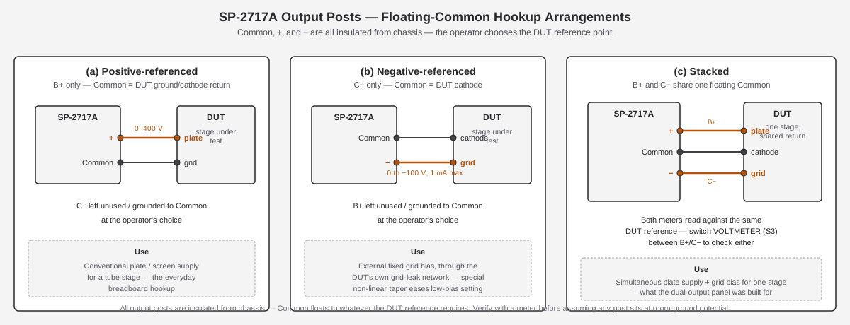
Table 7 — Series/stacked (B+ and C− referenced to the same floating Common)
| Arrangement | Common ties to | Active post(s) | Typical use |
|---|---|---|---|
| Positive-referenced | DUT ground / cathode return | + (B+) | Plate/screen supply for a stage under test |
| Negative-referenced | DUT cathode | − (C−) | External fixed grid bias for a stage under test |
| Stacked | DUT cathode (shared) | Both + and − | Simultaneous plate supply and grid bias for one stage, one shared reference |
⚠ Danger — a floating Common is only floating until you clip a second ground reference onto the same circuit. If a scope probe’s ground clip, a second instrument’s chassis, or a bench ground strap gets attached to a DUT node that this supply has floated away from chassis ground, you may create an unintended current path — potentially through the supply’s own regulator, or through you. Plan every ground/reference connection in a stacked or floated setup before powering up, not by clipping leads on one at a time while the rail is hot.
4.8 The Filament Output
The 6.3 V AC @ 4 A and 12.6 V AC @ 2 A posts come directly off the filament transformer T2, independent of the B+/bias regulator entirely — they stay live any time the AC POWER switch is ON, in both STANDBY and DC ON (§ 4). Both windings/taps may be drawn simultaneously, provided the combined load does not exceed 25 VA total (roughly: full 4 A at 6.3 V or full 2 A at 12.6 V already uses the full budget — don’t expect to draw both at their individual maximums at once).
Typical use: powering the heater string of the tube(s) under test, independent of whatever supply is providing their plate/screen/bias voltages (this supply’s own B+/C− outputs, or another bench supply entirely). Because these are AC posts off an isolated secondary winding — not referenced to Common, B+, C−, or chassis — they can also be floated to whatever DC bias point the DUT’s cathode circuit requires, same as the DC outputs in § 7.
⚠ Danger — the filament posts are low-voltage but not low-hazard by association: they sit on the same chassis as the HV section, and heater-to-cathode insulation ratings on tubes under test are finite. Don’t assume a “just filament wiring” connection is exempt from the general HV discipline in § 10 if it’s anywhere near a DUT that also carries plate/bias voltage from this or another supply.
4.9 Connecting a DUT and Stepping Current
This is the procedure that ties § 5–8 together for the actual job this supply is for: powering a tube circuit under test.
- With the supply at STANDBY (or AC POWER off) and both VOLTS controls at CCW/zero, wire the DUT per the hookup arrangement chosen in § 7. Double-check polarity at the DUT before applying any power — a plate supply wired backward, or a bias supply wired with the wrong polarity to a grid, is a fast way to destroy a tube or a device under test even at modest voltage.
- Confirm the DUT’s own heater/filament supply (this supply’s filament posts, per § 8, or an external source) is on and the tube(s) under test are warmed up, same as § 3’s warm-up applies to the SP-2717A’s own internal tubes.
- Power the SP-2717A up per § 3. Both VOLTS controls remain at zero through DC ON.
- VOLTMETER switch to B+. Watch M2 (mA) throughout the next step — it is your real-time overload indicator, and nothing else in the circuit will stop you if it climbs too far (§ 10.4).
- Bring B+ up in small increments, pausing at each step to observe M2. Don’t sweep the B+ VOLTS control straight to a target voltage on an unfamiliar or newly-repaired DUT — bring it up gradually (tens of volts at a time is reasonable for an unknown load) and watch both meters as you go. If M2 climbs faster than expected for the voltage step you just made, stop and investigate before continuing — that’s the signature of a DUT drawing more current than intended (a fault, a wiring error, or simply a circuit design that draws more than expected at that operating point).
- Set bias (C−) per § 5.2 if the arrangement calls for it, before or interleaved with B+ steps as the DUT circuit requires (some circuits need bias established before plate voltage is safe to apply — know your DUT’s own requirements, this supply doesn’t enforce a sequence for you).
- At target operating point, note both M1 (on whichever VOLTMETER switch position you need) and M2 for the logbook. Standard practice per the hub voice: record actual measured values, not just dial settings — “B+ set to 250 V, M2 reads 62 mA” is a log entry; “set B+ to about a quarter turn” is not.
- Never exceed 100 mA sustained on M2. 125 mA is stated as intermittent only. There is no supply-side protection against sustained overcurrent beyond the mains fuse and the pass tubes’ own dissipation limit — see § 10.4.
- To change the DUT, reduce B+ and bias back toward zero, then STANDBY, rather than disconnecting anything while the rail is hot. Re-warm is not required (§ 4) if you’re staying in STANDBY rather than cycling AC POWER off.
4.9.1 Worked example — a stacked plate-supply-and-bias hookup
The following walks the procedure above through a representative case: powering one output tube stage (a single pentode or beam tube under test) with the SP-2717A supplying both plate voltage and grid bias from a shared floating Common at the tube’s cathode (the § 7.3 “stacked” arrangement).
- DUT wired per § 7.3: SP-2717A Common → DUT cathode, + → DUT plate (through the DUT’s own load resistor or output transformer primary, as the circuit calls for), − → DUT control grid (through the DUT’s grid-stopper resistor). SP-2717A 6.3 V filament post → DUT heater, independent of the plate/bias wiring. VOLTS controls both at zero; S2 at STANDBY.
- DUT heater warmed up (either from the SP-2717A’s own filament post or an independent source, per § 8); SP-2717A itself warmed up per § 3.
- VOLTMETER switch to C−; set bias first — for this walkthrough, say the DUT’s data sheet or a prior known-good operating point calls for roughly −20 V grid bias. Bring C− VOLTS up slowly (remember the non-linear taper, § 5.2) until M1 reads −20 V on the amber (C−) lamp.
- VOLTMETER switch to B+; DC ON if not already. Bring B+ VOLTS up in increments — for example 50 V, 100 V, 150 V — pausing at each to confirm M2 tracks a sane current for that plate voltage against the bias already established. A current that jumps disproportionately at some step (rather than rising smoothly with plate voltage, as an ordinary biased tube stage should) is the signal to stop and investigate, not to continue toward the target.
- Reaching the target plate voltage (say 250 V) with M2 settled at a steady reading well under 100 mA, log both: “B+ 250 V / M2 62 mA / C− −20 V.” That triple is the actual operating point — the number the next session (or the write-up) needs, not “B+ knob at about 60%.”
- To change grid bias mid-test (a common exploration on a breadboarded stage — sweeping bias to see its effect on plate current), you may adjust C− VOLTS with B+ still applied, watching M2 respond — this is normal use of the stacked arrangement and does not require dropping back to STANDBY. Do drop back to STANDBY (§ 4) before changing any wiring.
4.10 Safety — This Is Lethal Voltage
Everything above assumes the operator respects what follows. Read this section fully, even if you’ve skimmed the callouts scattered through the rest of the volume — it collects the whole-instrument hazard picture in one place.
4.10.1 Where the energy lives
Table 8 — Where the energy lives
| Node | Nominal potential | Notes |
|---|---|---|
| B+ output posts | 0–400 V DC, regulated | What you dialed in with B+ VOLTS |
| C− output posts | 0 to −100 V DC | What you dialed in with C− VOLTS |
| C2/C3 doubler reservoir caps (internal) | ~600 V DC raw, unregulated, at no load | Upstream of the regulator entirely — feeds the 6L6GC plates directly. This is present whenever the AC POWER switch has been ON recently, STANDBY or not. |
| Internal negative rail (feeds ZD1–ZD10, C4/C5) | up to −300 V DC | The reference/control-amp supply — see Vol 2 § 2, Vol 3 § 4 |
| Mains input | 110–130 V or 220–260 V AC | Ordinary but real mains hazard, on top of everything above |
⚠ Danger — the raw ~600 V rail is present any time the AC POWER switch has been on recently, regardless of STANDBY/DC ON position, and regardless of what the front-panel meters read. STANDBY (§ 4) removes the regulated output from the panel posts; it does not touch C2/C3 or the negative-rail capacitors. A meter reading 0 V on the panel tells you nothing about the charge sitting on the doubler caps inside the case.
4.10.2 The bleeder is not a safety discharge
The R15–R18 bleeder network (four 27 kΩ / 2 W resistors in series, ≈108 kΩ total, connected between the B+ bus and the −300 V rail) exists for one purpose: it provides a minimum standing current path so the 6L6GC pass tubes stay in conduction — and therefore in regulator control — at zero external DUT load. It is a minimum-load bleeder, sized for regulation stability, not a fast safety-discharge resistor.
Note carefully where this bleeder actually sits in the circuit: it ties into the B+ bus, which is the regulated output side, at the pass tubes’ cathodes. C2 and C3 — the 68 µF doubler reservoir caps that hold the raw ~600 V — are upstream of that, feeding the 6L6GC plates. Any discharge path from C2/C3 down to the bleeder has to pass through the pass tubes themselves, and as those tubes cool after shutdown they stop conducting — so there is no guaranteed, well-defined discharge path or time constant carrying the bleeder’s effect back to C2/C3 once the tubes go cold. Do not estimate a “safe by now” wait time from the bleeder’s resistance value; it was never sized as a discharge path for those capacitors and its behavior after shutdown is not something to reason your way through informally.
⚠ Danger — manually discharge C2/C3 and the negative-rail caps before reaching into the chassis. Do not rely on the bleeder, on elapsed time alone, or on a “the meter reads zero” observation. Before any work inside the case:
- Switch AC POWER off and unplug the line cord.
- Wait at least a minute for the bleeder’s natural decay to do its share.
- Manually short C2 and C3 to the chassis/common return through a suitable HV discharge tool (an insulated-handle resistor-tipped discharge probe — a bare screwdriver shorting 600 V-class caps is itself a hazard from the resulting arc/spark and can weld pitting into the terminal). Do the same for the negative-rail capacitors (C4, C5). Discharge to Common/chassis-ground reference; confirm on your handheld meter.
- Verify zero volts with a meter you trust — on both the positive doubler node and the negative rail — before touching anything. Never assume; always confirm.
Build a discharge habit, not a one-time ritual. A dedicated HV discharge probe — an insulated shaft terminating in a resistor (commonly a few hundred ohms to a few kΩ at a suitable wattage, sometimes with a built-in neon or LED indicator that confirms current is actually flowing) clipped or shorted to Common — should live in the same drawer as this supply, not be improvised from whatever screwdriver is closest when the case is open. A resistor-limited discharge tool avoids the sharp current spike (and resulting terminal pitting, or a startling snap/spark at your hand) of a dead short across a charged 68 µF cap at several hundred volts. Discharge, then confirm with a meter — the probe tells you current flowed, not that the node reached zero; only a meter reading across the node itself confirms that.
PPE is not overkill on this instrument. Safety glasses when working inside the case (an arc from an accidental short can throw sparks and, rarely, cap material), and if you’re at all unsure of your own technique or unfamiliar with this specific unit’s internal layout, treat it as a two-hands-never job: verify de-energized state with a meter, then work — don’t probe a “probably discharged” node live to save the extra minute.
4.10.3 One-hand rule
Above roughly 50 V, work with one hand only near live or possibly-live circuitry; keep the other hand
in your pocket or braced away from any grounded surface. The physiological hazard of electric shock is
overwhelmingly a function of current through the chest/heart, which a hand-to-hand path across the torso
maximizes; a hand-to-same-side-foot path is comparatively (not absolutely) safer. This is baseline bench
discipline for any HV tube gear per _shared/legal_ethics.md — it
applies with particular force here given the doubler caps’ stored energy.
4.10.4 No B+ foldback — respect the 100 mA rating
Repeating from § 6.2 and § 9 because it is the single most important operating limit on this instrument: there is no active current-limit or foldback circuit on the B+ output. The manual’s circuit description contains no B+ overcurrent protection scheme — the only things standing between an overloaded or shorted B+ output and a damaged supply (or worse) are:
- The mains fuse (1.5 A slow-blow at 110–130 VAC / 1.0 A at 220–260 VAC) — which protects against a catastrophic fault, not against sustained mild overload, and which is upstream of the whole instrument, not specific to the B+ path.
- The 6L6GC pass tubes’ own plate-dissipation limit — which is why the rating is stated as 100 mA continuous / 125 mA intermittent only: beyond that, the pass tubes themselves are the failure point, dissipating more heat than they’re built to shed continuously.
Compare this to the bias (C−) output, which does have dedicated protection — the 22 kΩ current-limiting resistor R20 explicitly sized, per the manual, to prevent damage if the negative output is accidentally shorted or overloaded. B+ has no equivalent. Treat the M2 milliammeter as your only real-time overcurrent warning, and treat the 100 mA continuous rating as a hard operating ceiling you enforce yourself, not a spec the instrument will enforce for you.
4.11 Don’ts
Table 9 — Don'ts
| Don’t | Why |
|---|---|
| Assume STANDBY makes the chassis interior safe to touch | Kills only the regulated output at the panel posts; C2/C3 and the negative-rail caps stay charged (§ 4, § 10) |
| Trust the bleeder (R15–R18) as a fast safety discharge | It’s a minimum-load bleeder sized for regulator stability, not a rapid discharge path (§ 10) |
| Reach inside the case without manually discharging C2/C3 and the negative-rail caps first, verified with a meter | Raw doubler voltage is ~600 V; residual charge outlasts a casual wait (§ 10) |
| Sustain M2 above 100 mA (or above 125 mA at all, beyond brief intermittent excursions) | No B+ current-limit exists; the pass tubes’ dissipation limit and the mains fuse are the only backstops (§ 10.4) |
| Trust a number on M1 without checking the red/amber lamp and the VOLTMETER switch position first | M1 is a shared meter between B+ and C− — a misread swaps a “safe-looking” bias number for a lethal B+ number or vice versa (§ 6.1) |
| Load the bias (C−) output beyond its 1 mA rating “just a little” | R20 protects against a dead short, but sustained overload can burn the C− VOLTS pot (R19) itself (§ 5.2) |
| Sweep the B+ VOLTS control straight to a target voltage on an unfamiliar DUT | Step it up in increments watching M2, so a wiring fault or unexpected draw shows up before it becomes a real overload (§ 9) |
| Assume a floating Common is at room-ground potential | The output posts are deliberately insulated from chassis; a Common tied to an elevated DUT node can be live with respect to the bench (§ 7) |
| Clip a second ground reference (scope probe, another instrument) onto a floated circuit without planning the whole reference scheme first | Can create an unintended current path through the regulator, the DUT, or you (§ 7) |
| Power up an unfamiliar or long-stored unit straight to full mains, full voltage | Reform electrolytics on a Variac first — see Vol 5, and § 2 of this volume |
| Cycle AC POWER off/on repeatedly through a session instead of using STANDBY | Ages tube heater-cathode structures unnecessarily and re-imposes the multi-minute warm-up every time (§ 4) |
| Skip the pre-power inspection because “it worked fine last time” | Line cords, fuses, and posts degrade; verify every session (§ 2) |
4.12 Cross-References
- Vol 1 — what this instrument is, its place in the PS-4 → IP-32 → IP-17 → IP-2717 → SP-2717A lineage, and why “SP” is the correct model designation for a factory-assembled 1982 Heath-Zenith unit.
- Vol 2 §§ 1–2 — how the series-pass regulator (6AU6 error amp, 6L6GC pass tubes, ten-zener reference stack ZD1–ZD10) actually holds B+ and provides the reference this volume’s controls are adjusting against.
- Vol 3 §§ 1, 4 — the device complement and control/metering hardware this volume assumes you can already locate on the panel and chassis (S1–S3, R10–R19, M1/M2, R23/R24, T1/T2).
- Vol 5 — full recalibration procedure (ZERO VOLTAGE ADJUST R10, 400 VOLT ADJUST R14), electrolytic recap guidance (C1–C5, C8, C10) and known failure modes (shorted 6AU6, shorted zeners) that an operator should recognize as symptoms during the procedures in this volume.
- Vol 6 — condensed cheatsheet of the numbers in this volume, plus the honest IP-32/SP-2717A generational comparison (both units share this exact operating procedure and the exact same hazards — same 0–400 V/ 100 mA B+ rating, same lack of B+ foldback, same class of stored-energy risk on their respective doubler/rectifier reservoirs).
_shared/legal_ethics.md— the hub-wide HV/mains/tube-gear bench discipline (isolation transformers, GFCI, one-hand rule, hazardous legacy materials) that this volume’s § 10 specializes for the SP-2717A specifically. Read it in full if you have not already.
Sources
- Heath Company, “Model SP-2717A Regulated High Voltage Power Supply,” operation/service manual 595-2705-02, © 1982 (Benton Harbor, MI) — Specifications, Operation, Circuit Description, and Recalibration sections. Full text via Internet Archive: https://archive.org/details/Heathkit_SP-2717A_Regulated_HV_Power_Supply
- Bob Eckweiler (AF6C), “Heathkit of the Month #67 — IP-32 Bench HV Power Supply,” Orange County Amateur Radio Club, © 2015 (family lineage, sibling IP-32 circuit and operating characteristics): https://www.w6ze.org/Heathkit/Heathkit_067_IP32.pdf
- “Heathkit Zenith SP-2717A Power Supply Restore,” Lazy Electrons, 2018-06-02 (restorer field notes on bias-pot loading and zener-stack heat behavior): https://lazyelectrons.wordpress.com/2018/06/02/heathkit-zenith-sp-2717a-power-supply-restore/
- Radiomuseum, “Heath (Heathkit-Regulated) Regulated HV Power Supply IP-2717A” (unit identity cross-reference): https://www.radiomuseum.org/r/heath_regulated_hv_power_supply_ip_2717a.html