Heathkit SP-2717A HVPS · Volume 5
Heathkit SP-2717A — Vol 5: Calibration & Refurbishing
A 1982 lethal-voltage lab supply that has probably sat unused for decades — here is the order of operations that gets it back in spec without hurting anyone.
5.1 Scope of This Volume
Vol 3 documented what is inside this chassis; Vol 4 documented how to drive it safely from the front panel. This volume is about the bench work that sits between “acquired a forty-year-old high-voltage supply” and “trust it on a tube project”: the recap, the device-wear checks on the regulator and reference chain, the meter and calibration-pot procedure, a symptom-to-fix reference table, and where to source the parts. It assumes the reader has already read Vol 3 §“Circuit Description” for the block-level layout (V1 the 6AU6 error amp, V2/V3 the 6L6GC pass tubes, D1–D9 silicon rectifiers, ZD1–ZD10 the zener reference stack) and Vol 4 for the front-panel control layout and the operating sequence this volume’s calibration steps build on.
The order below is deliberate and should not be reshuffled: discharge first, then inspect and recap, then check the active devices, then calibrate, then verify against the failure table if anything still looks wrong. Every one of those steps happens with the cover off on a chassis that can still be carrying several hundred volts on exposed nodes — read the next section before you pick up a screwdriver.
⚠ Danger — this is a regulated high-voltage supply, not a low-voltage bench instrument. The raw B+ bus runs to roughly +600 V DC at no load before regulation, the regulated B+ output goes to 400 V DC, and a –300 V reference rail is present on the circuit board during every calibration step in this volume. Read the hub-wide
_shared/legal_ethics.mdbefore opening the case, and Vol 4 §“HV Safety” for this instrument’s operating-time precautions — this volume covers the service-time precautions, which are stricter because the cover is off and your hands are inside.
5.2 Before You Touch Anything — Discharge Discipline
5.2.1 The bleeder is not a safety discharge
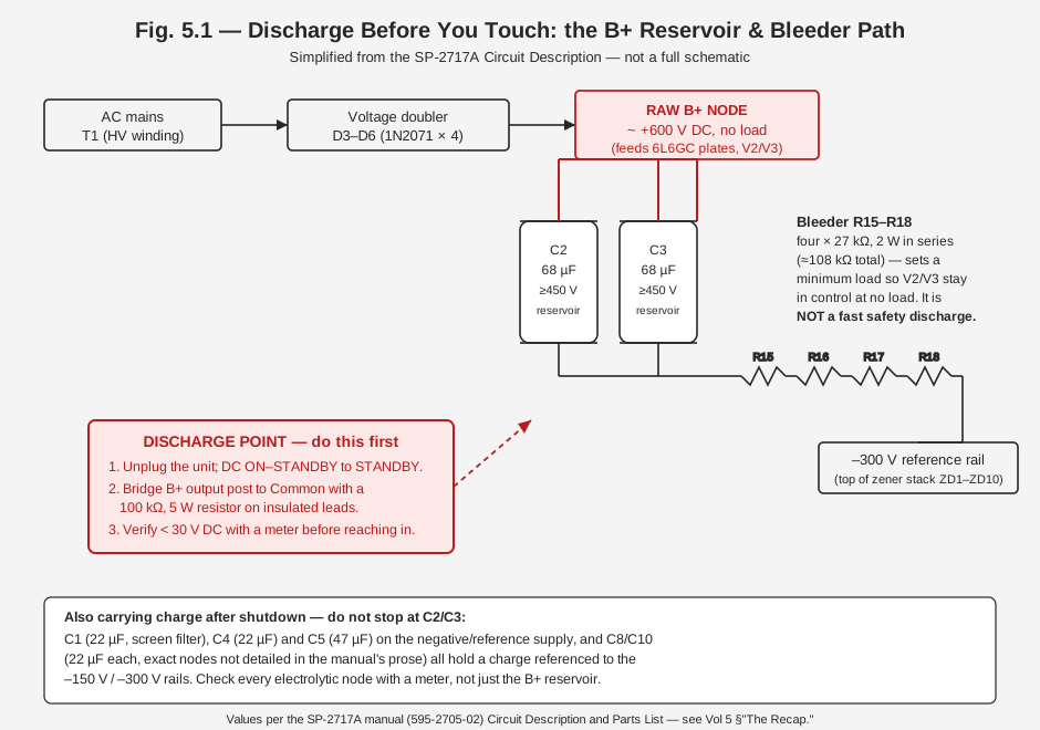
It is tempting to read Vol 3’s description of the R15–R18 bleeder (four 27 kΩ, 2 W resistors in series, roughly 108 kΩ total, tied between the B+ bus and the –300 V reference rail) and assume that network exists to bleed the supply safe after shutdown. It does not. The manual states its purpose plainly: it provides a minimum-current path so the 6L6GC pass tubes keep conducting at zero external load, which keeps the regulator loop in control when nothing is plugged into the output posts. That it also slowly discharges the reservoir caps is a side effect, not the design intent, and “slowly” is doing real work in that sentence.
A rough order-of-magnitude estimate is useful here, with the caveat that it is an engineering estimate from the known R and C values, not a number printed in the manual: roughly 108 kΩ of bleeder resistance against a B+ reservoir on the order of 68–136 µF gives a time constant τ = RC on the order of 10–15 seconds, meaning five time constants — the usual rule of thumb for “essentially discharged” — is on the order of a minute or more, not the “unplug it and wait ten seconds” instinct a lower-voltage instrument might train. Treat that as a floor, not a target: always verify with a meter before you reach in, regardless of how long the unit has sat unplugged.
⚠ Danger — do not trust elapsed time alone. A weak or open bleeder resistor (they are 2 W parts that have now been dissipating for over four decades) removes the only passive discharge path entirely, and a supply with a failed bleeder can sit at lethal voltage indefinitely with the cover off and the AC cord unplugged. This is exactly the kind of failure a meter check catches and a stopwatch does not.
5.2.2 Discharge procedure
- DC ON–STANDBY (S2) to STANDBY, then AC POWER (S1) OFF, then unplug the line cord. Do not rely on STANDBY alone — it removes the DC path to the load but does not itself discharge the reservoir caps.
- With the cover off, bridge the B+ output post to the Common post with an insulated-lead discharge resistor — 100 kΩ, 5 W is a reasonable working value for this supply’s stored energy (a bare screwdriver short across a 68 µF cap charged to several hundred volts is a genuine arc-flash and pitting hazard on the cap terminals themselves, not just a shock hazard to you). Hold the leads with insulated tools, not bare fingers, until you have confirmed a low reading.
- Verify with a DMM in DC volts, one hand behind your back, at the B+ output post, at the C2/C3 reservoir cap terminals directly on the board, and at the negative-supply nodes (C4, C5). Confirm under 30 V DC at every point before doing any further work. If any node reads high after the discharge resistor has been applied for a minute or more, suspect an open bleeder resistor or a bad discharge lead connection — do not proceed until you understand why.
- Only then remove the board, probe components, or reach near the doubler cap terminals.
Fig. 5.1 below traces this path from the AC input through the doubler to the discharge point, and flags the negative-supply and screen-supply capacitors that also hold charge and are easy to forget because they are not the biggest cans on the board.
5.2.3 One-hand rule, every time
Everything in this volume happens with a live meter probe near a board that can still be carrying a
regulated 400 V or an unregulated ~600 V, depending on where in the sequence you are. Keep the
one-hand rule from Vol 4 in force for the entire service session, not just the discharge step — the
temptation to brace the chassis with a free hand while probing with the other is exactly the failure
mode that rule exists to prevent. See _shared/legal_ethics.md for
the hub-wide statement of this and related mains/HV practices, which this volume assumes throughout.
5.3 Tools & Bench Setup for This Service Session
None of the work in this volume needs exotic equipment, but a few specific items make the difference between a controlled service session and a guessing game on a lethal-voltage board. This list assumes the discharge procedure above has already been performed and is not itself a substitute for it.
Table 1 — Tools & Bench Setup for This Service Session
| Tool | Role in this service session | Notes |
|---|---|---|
| DMM, DC volts to ≥600 V | Discharge verification, rail checks, output calibration cross-check | The single most-used tool in this volume — every step above the “unplug it” line involves a meter reading before proceeding |
| Insulated-lead discharge resistor (≈100 kΩ, 5 W) | Discharge procedure | Build one on a pair of insulated test leads and keep it dedicated to HV work rather than improvising one each session |
| Insulated trim tool(s) | R10/R14 board-pot adjustment with the cover off and DC ON | A metal screwdriver bridging a trimmer body to an adjacent HV trace is exactly the kind of mistake this volume exists to prevent |
| Tube tester or curve tracer | 6L6GC and 6AU6 device-wear checks | Jeff’s bench carries both a Heathkit TT-1 mutual-conductance tester and pulsed-HV curve tracers (eTracer, uTracer6) — either answers “is this tube still good,” and the curve tracers additionally show how it has degraded |
| Capacitance/ESR meter | Recap decision-making (§“Measuring Before You Replace” below) | Out-of-circuit measurement is more reliable than in-circuit for this board’s electrolytics |
| Variable isolation transformer (variac) | Bring-up after any board-out service (§“Bring-Up After Service” below) | Jeff’s B&K 1653A is the natural fit here — metered, isolated, and rated well above this supply’s 150 W maximum draw |
| Analog VOM (optional, for cross-checking) | A second, independent instrument for the calibration cross-check in §“Meter Re-Zero & Calibration” | A Simpson 260-class VOM is a reasonable secondary reference, though its 20 kΩ/V loading matters less here than on a high-impedance grid-bias measurement — B+ and C– are both low-impedance, actively regulated outputs |
Note — an ESR meter specifically is listed in the hub’s comparison matrix as a category Jeff has not yet acquired (
TBDin the top-level instrument table). Capacitance-only measurement out-of-circuit is still useful for catching a grossly degraded electrolytic even without ESR — treat ESR as the more sensitive test to add to the bench later, not a hard prerequisite for the recap decision in this volume.
5.3.1 Why an isolation transformer, not just the wall
Working on an open-chassis HV supply directly off the building’s mains ties the chassis (and, through a slip of a probe, you) to earth ground through the shortest possible path if anything goes wrong. Running the unit through an isolated variac breaks that direct path and — just as usefully for this particular instrument — lets you bring the AC input up from 0 V gradually rather than slamming a decades-idle supply straight to full line voltage. §“Bring-Up After Service” below covers the specific procedure; this section is only flagging that the variac earns its place on the bench before you get there, not after.
5.4 The Recap
5.4.1 Why recap a 1982 unit at all
The SP-2717A is a Heath-Zenith-era instrument — 1982, not a pre-1970 unit — so it does not carry the worst of the vintage-electrolytic failure modes (dried-out wax-and-paper types, for instance) and it has no selenium rectifiers at all, unlike its IP-32 sibling (Vol 6 §“The Generational Pair”). But “1982” is still over four decades old by any realistic service date, and aluminum electrolytics have a service life measured in decades under good conditions and considerably less under the elevated temperatures this instrument’s own 6L6GC pass tubes generate inside a closed chassis. Bulging, leaking, or high-ESR electrolytics are the single most common age-related failure across the whole Heath HV-supply lineage, and they are cheap and low-risk to replace proactively as a baseline service step even before chasing a specific symptom.
Note — this is a recap-as-preventive-maintenance section, not a “these caps are definitely bad” claim about any specific unit. Measure before you replace where you can (capacitance and ESR out-of-circuit), and treat the table below as the shopping list for when you decide to recap, not a mandate to gut a unit that tests fine.
5.4.2 Recap BOM — electrolytics
Table 2 — Recap BOM — electrolytics
| Ref | Value | Voltage rating | Heath part no. | Circuit role | Notes |
|---|---|---|---|---|---|
| C1 (C1A/C1B) | 22 µF | Not specified in the manual — screen-supply rail is derived off the raw HV bus, so treat conservatively | 25-955 | Screen-grid supply filter (after half-wave rectifiers D1, D2) | Feeds V2/V3 screens through parasitic-suppressor resistors R2, R3 |
| C2 | 68 µF | ≥450 V-class (500 V recommended) | 25-956 | B+ voltage-doubler reservoir | Sees the full raw B+ swing, ~600 V at no load — the highest-stress cap on the board |
| C3 | 68 µF | ≥450 V-class (500 V recommended) | 25-956 | B+ voltage-doubler reservoir | Paired with C2 in the D3–D6 doubler; same voltage stress |
| C4 | 22 µF | Not specified — negative-supply rail | 25-955 | Negative/reference supply filter after D7–D9 | Feeds R27 → C5 → the ZD1–ZD10 zener stack |
| C5 | 47 µF | Not specified — negative-supply rail | 25-957 | Negative/reference supply filter, second stage | Downstream of C4/R27; smooths the –150/–300 V reference source |
| C8 | 22 µF | Not specified | 25-955 | Filter, exact node not detailed in the manual’s Circuit Description prose | Confirm against the schematic fold-out before ordering a substitute with different footprint/lead spacing |
| C10 | 22 µF | Not specified | 25-955 | Filter, exact node not detailed in the manual’s Circuit Description prose | Same part number as C1/C4/C8 — likely a general-purpose 22 µF filter position |
⚠ Danger — C2 and C3 are the highest-stress, highest-hazard parts on this board. They sit directly across the B+ doubler and see the raw ~600 V no-load swing before regulation even engages. A restorer’s field report used 450 V-rated replacements; given the ~600 V no-load figure, a 500 V-rated part leaves more margin and is the safer specification if the physical size still fits the board — do not substitute a 350 V or 400 V part here even if it is a cheaper or more common stock item.
Non-electrolytic capacitors on the board — C6 (0.2 µF Mylar), C7 (0.056 µF Mylar), C9 (0.05 µF paper) — are not part of the standard recap and are generally reliable at this instrument’s age and voltage class. Check them for obvious physical damage (cracked case, discoloration near a hot component) but do not replace them prophylactically; film and Mylar types do not share the electrolyte dry-out failure mode that drives the recap decision on C1–C5, C8, and C10.
5.4.3 Measuring before you replace
A blanket recap is defensible as preventive maintenance on a unit this age, but it is not the only valid approach, and measuring first has real value even if you end up replacing every electrolytic on the board anyway — it gives you a documented before state to compare against after service, which is the difference between “I recapped it and it works now” and an actual diagnosis.
With each electrolytic desoldered (or at minimum one leg lifted) and the board otherwise unpowered and discharged:
- Capacitance should read close to the marked value — modern electrolytics are typically ±20%; a forty-year-old part reading well under 50% of marked value has likely dried out and should be replaced regardless of what else you find.
- ESR (equivalent series resistance) is the more sensitive indicator — a cap can measure close to its rated capacitance and still have degraded badly in ESR, which shows up as excess ripple or heat under load even though a capacitance-only check would pass it. Compare against typical ESR figures for the part’s capacitance/voltage class rather than a single fixed threshold; a part reading several ohms where a healthy same-class part should read well under an ohm is the signature to act on.
- Visual inspection still matters and is faster than either meter: bulging or domed can tops, any sign of electrolyte weeping from the vent or the base seal, and discoloration of the board around the can are all disqualifying on their own, independent of what the meter says.
Log whatever you measure, even informally — a simple table works:
Table 3 — Log whatever you measure, even informally — a simple table works
| Ref | Marked value | Measured capacitance | Measured ESR | Visual | Disposition |
|---|---|---|---|---|---|
| C2 | 68 µF / ≥450 V | (record) | (record) | (record) | (replace / retain) |
| C3 | 68 µF / ≥450 V | (record) | (record) | (record) | (replace / retain) |
| C4 | 22 µF | (record) | (record) | (record) | (replace / retain) |
| C5 | 47 µF | (record) | (record) | (record) | (replace / retain) |
Fill this per the hub’s logbook convention — “Cap C2 measured 41 µF / ESR 6.8 Ω against 68 µF / <1 Ω marked — replaced with a 68 µF, 500 V-rated part” is a useful entry; “the caps were probably bad so I replaced them” is not, even if the underlying decision to recap proactively was the right call.
5.4.4 Board sequence notes
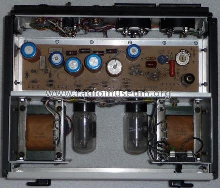
- The doubler caps (C2, C3) are physically the largest cans on the board and typically the easiest to identify by eye before you even open the parts list — if a restoration photo shows a Heath HV board with two noticeably larger electrolytics than everything else nearby, those are C2/C3.
- Because C2 and C3 are in a doubler configuration (not simple parallel filtering), replace them as a matched pair rather than mixing an old can with a new one — a capacitance mismatch between the two doubler stages unbalances the doubling action and can show up as excess ripple or an asymmetric no-load voltage even with the regulator otherwise healthy.
- After any recap, re-run the full discharge-and-verify procedure above before doing anything else — new caps hold charge exactly as well as old ones did, and a half-finished recap session with the board reinstalled and the AC cord plugged back in “just to check” is a common way this goes wrong.
5.5 Regulator & Reference Device Wear
This section covers the active devices most responsible for whether the supply actually regulates: the two 6L6GC series-pass tubes, the 6AU6 error amplifier that drives them, the ten-zener reference stack that replaced the older units’ VR tubes, and the silicon rectifiers feeding all of the above. Vol 2 covers how these devices work together in the control loop; this section covers what fails.
5.5.1 6L6GC series-pass tubes (V2, V3)
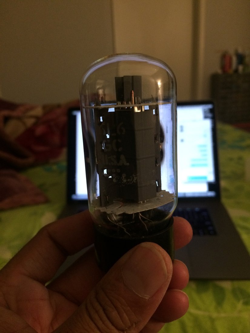
The two 6L6GC beam-power tubes are the supply’s dissipation element — Vol 2 covers why they are run as pentodes rather than triodes for headroom, but from a service standpoint the practical concern is simpler: these tubes sit in the highest-power, highest-heat position on the chassis and are the most mechanically stressed active devices in the unit.
- Symptom of a weak or gassy pass tube: poor regulation under load, inability to reach the full 400 V setpoint even with R14 (400 VOLT ADJUST) turned up, or a B+ output that sags noticeably as current draw increases toward the 100 mA continuous rating.
- Check: low emission or gas content shows up on a tube tester or curve tracer (Jeff’s bench has both — see the Curve Tracers overview and the Heathkit TT-1 for the general workflow); a side-by-side swap against a known-good 6L6GC pair is the faster field diagnostic if a tester is not handy.
- Sourcing: 6L6GC is one of the most widely produced audio/industrial beam-power tubes ever made — current-production and NOS stock are both readily available; see §“Parts & Tube Sourcing” below.
- Because V2 and V3 work as a matched pair sharing the pass-element load, replace both together rather than swapping only the weaker-testing tube, to avoid an imbalance between the two.
5.5.2 6AU6 control (error) amplifier — V1
The 6AU6 is the single point of failure with the highest leverage in this circuit: it is the DC feedback amplifier that compares a sample of the B+ output against the zener reference and drives both 6L6GC control grids to hold the output constant. There is exactly one of these tubes in the whole regulator loop.
Note — a shorted 6AU6 is a documented failure mode on this circuit family, reported in a restorer’s write-up of an SP-2717A restore, and the reported symptom is total loss of regulation — not a partial drift, but the control loop stops functioning as a control loop. If B+ output tracks the raw unregulated bus roughly 1:1 with the B+ VOLTS and calibration pots having no effect, suspect V1 first, ahead of the pass tubes or the zener stack.
The 6AU6 is a common sharp-cutoff pentode used across decades of tube-radio and instrument designs; it is inexpensive and easy to source (§“Parts & Tube Sourcing”), which makes it a reasonable first swap to try on a “regulator does nothing” symptom before committing to signal-tracing the feedback network.
5.5.3 Zener reference stack — ZD1–ZD10
The ten-zener stack is the part of this circuit that most visibly separates the SP-2717A generation from the older IP-32/IP-17 generation, which used a pair of 0A2 gas voltage-regulator tubes for the same job (Vol 6 §“The Generational Pair” covers this comparison in full). The stack sits in series across the negative supply and produces the regulated –150 V and –300 V reference rails the control amplifier and its divider networks depend on.
Note — shorted zeners are a documented failure mode, and the documented root cause is mundane: the zeners run genuinely hot mounted flat against the PCB, and thermal stress over decades of service degrades them. A restorer’s fix, worth adopting proactively during any board-out service session even if the stack currently tests good, is to stand the zener diodes off the board slightly on their leads rather than mounting them flush, improving convective cooling around each device. Losing even one zener in a ten-diode series stack shifts the entire –150 V/–300 V reference and, with it, the whole regulation setpoint — this is not a “replace the one bad diode and move on” repair without also rechecking calibration afterward (§“Meter Re-Zero & Calibration” below).
Practically, checking a ten-diode series stack in-circuit is awkward — a shorted individual zener drops the total stack voltage by that diode’s rated value, which on a healthy string should sum to the stack’s designed –150 V/–300 V reference points. If the reference rails measure low by roughly one zener’s worth of voltage, that is the signature to look for; isolate and test the string out-of-circuit or section-by-section if the in-circuit reading is ambiguous.
The solid-state board itself — the silicon rectifiers and the full ZD1–ZD10 stack in context — is pictured in Vol 3 §“Circuit Board”; this volume focuses on the service action rather than repeating that photo.
5.5.4 Silicon rectifiers D1–D9 (1N2071)
Nine 1N2071 silicon diodes do all of this supply’s rectification: D1/D2 (half-wave, screen supply), D3–D6 (full-wave doubler, B+), and D7–D9 (negative/reference supply). The 1N2071 is roughly a 600 PIV part and equivalents are common. Check for opens (no rectification, corresponding filter cap never charges) or shorts (excess ripple, or in the doubler position a dead-short across the AC line winding that can also take out the mains fuse). Silicon rectifiers of this era are generally reliable — this is a lower-probability failure point than the tubes or the zener stack, but cheap enough to check with a diode-test function while the board is already out for other service.
5.5.5 Failure interaction — why device order matters
Because the 6AU6 compares the B+ sample against the zener-derived reference, a fault in either device can present as “the calibration pots don’t work” even though only one of them is actually broken. The practical diagnostic order that avoids chasing calibration ghosts:
- Confirm the raw HV bus and negative reference rails are present and roughly at their expected levels (Vol 3 §“Outputs” for the reference numbers) with the board out of the loop where practical.
- Confirm V1 (6AU6) is not shorted or dead — swap-test is the fastest field check.
- Confirm the zener stack sums to its designed reference voltage.
- Only then proceed to the R10/R14 calibration procedure below — recalibrating against a bad reference or a dead error amp will not hold, and re-adjusting the pots repeatedly while chasing a device fault is a common way to wear out R10/R14 themselves for no diagnostic benefit.
5.6 Bring-Up After Service — Using a Variac
Any time this instrument has been apart for a recap, a device swap, or an unknown length of storage before you acquired it, resist the instinct to plug it straight into the wall and flip AC POWER. A gradual bring-up on an isolated variac catches problems — a leaky new cap, a solder bridge from rework, a rectifier installed backwards — at low voltage and low stress, instead of at full line voltage with the full ~600 V raw bus already established.
- Cover on or fingers well clear, DC ON–STANDBY at STANDBY, variac at 0 V AC output.
- Bring the variac up slowly — in roughly 20–30 V AC steps — while watching for smoke, unusual smell, or arcing sound. Pause at each step; do not sweep continuously to full voltage.
- At each step, check that the filament/AC output behaves as expected (T2, the filament transformer, runs independently of DC ON–STANDBY per Vol 3’s dual-transformer design) and that nothing on the chassis is warming unexpectedly.
- Once at full line voltage with DC still in STANDBY, confirm no anomalies, then move DC ON–STANDBY to DC ON and watch M2 (the 0–150 mA current meter) as the pass tubes come up — a healthy no-load condition should settle near the bleeder’s minimum-current level, not climb continuously or trip the mains fuse.
- Only after a clean bring-up at full line voltage with no load do you proceed to the calibration procedure below.
⚠ Danger — a variac provides voltage isolation and gradual ramp-up; it does not current-limit the way a bench power supply’s constant-current mode does. A genuine dead short downstream (for example, a rectifier installed backwards in the doubler) can still draw excessive current even at a partially-advanced variac setting. Watch M2 and be ready to bring the variac back to 0 V immediately if current climbs faster than expected at any step.
This step is not in the manual’s own Recalibration procedure — the manual assumes a unit that has been in continuous or near-continuous service, not one just pulled out of decades of storage or freshly reassembled after a recap. Treat it as the bridge between “the board work is done” and “now follow the manual’s Recalibration section,” not a replacement for either.
5.7 Meter Re-Zero & Calibration
5.7.1 Warm-up and thermal settling
Every device in this circuit that the calibration procedure depends on has some temperature sensitivity: cathode emission and gas content in the 6L6GC pass tubes and the 6AU6 error amp, and the temperature coefficient of the zener reference stack itself. Heath’s own step 3 in the Recalibration sequence — “warm up filaments several minutes, then DC ON” — exists because of exactly this, and it is worth understanding why, not just following it mechanically: a calibration set against a reference that has not yet reached thermal equilibrium will appear to drift over the following several minutes even with nothing touched, and a rushed calibration pass chasing that drift wastes time re-adjusting pots that were never actually wrong.
Vol 3 covers the reason this supply keeps a separate filament transformer (T2) independent of the DC ON–STANDBY switch — it lets the tube filaments stay warm through STANDBY specifically to avoid repeated cold-start warm-up cycling. If the unit has just been powered up from a fully cold state (first power-up after service, or after being fully unplugged rather than left in STANDBY), give it more than the bare minimum warm-up time before starting the calibration procedure below; if it has been sitting in STANDBY with filaments already warm, the settling time needed before DC ON is shorter.
Note — the manual does not print an exact number of minutes for “several minutes” of warm-up, and no more specific figure could be verified for this instrument specifically. Treat it as a floor, not a target — watch M1 for continued drift after the nominal warm-up period and do not proceed with calibration adjustments until the reading has stabilized, however long that takes on a given day and ambient temperature.
The manual’s Recalibration section is short, but the two internal pots it adjusts genuinely interact with each other, which is the part most likely to trip up a first pass. This section walks the procedure in the same order the manual specifies, with the mechanical step first because skipping it silently offsets everything downstream.
5.7.2 Mechanical zero — do this before anything electrical
M1, the dual-scale 0–400 V / 0–150 V voltmeter, has a conventional analog-meter mechanical zero adjustment: a slotted screw on the meter face itself. With the unit powered off, turn that screw until the pointer rests exactly on 0. This has nothing to do with the circuit and everything to do with the meter movement’s spring tension having crept over decades of storage and handling — skip it and every subsequent electrical calibration step will be chasing an offset that has nothing to do with R10 or R14.
5.7.3 R10 ZERO VOLTAGE ADJUST and R14 400 VOLT ADJUST — and why they interact
The two circuit-board calibration controls are accessed from the top of the board:
Table 4 — The two circuit-board calibration controls are accessed from the top of the board
| Designator | Function | Value | Sets range for |
|---|---|---|---|
| R10 | ZERO VOLTAGE ADJUST | 500 kΩ | Paired with R11 (680 kΩ, fixed range-setting resistor) |
| R14 | 400 VOLT ADJUST | 200 kΩ | Paired with R13 (240 kΩ, fixed range-setting resistor) |
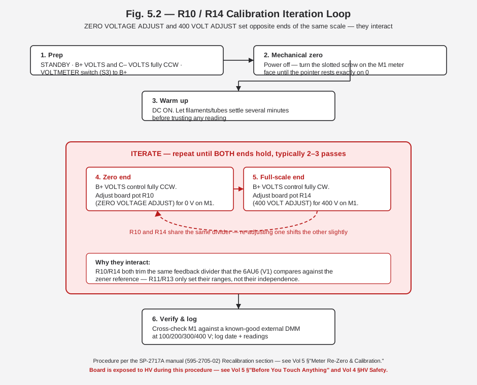
R10 and R14 both trim the same feedback divider network that the 6AU6 compares against the zener reference — R11 and R13 set the ranges those two pots operate over, but they do not decouple R10 and R14 from each other. Adjusting one shifts the effective transfer function the other one is working against, which is why the manual’s own procedure is written as an explicit iterate-until-stable loop rather than a single pass through each pot.
⚠ Danger — the calibration board is exposed with the cover off and the supply in DC ON, which means this entire procedure happens with a board carrying up to 400 V regulated (and the ~600 V raw bus feeding it) live and accessible. The manual explicitly warns of exposed high-voltage areas on the board during adjustment. Use insulated trim tools, keep your free hand clear of the chassis, and treat every pass through this procedure with the same one-hand discipline as the discharge step above.
5.7.4 Step-by-step procedure
Table 5 — Step-by-step procedure
| Step | Action | Target |
|---|---|---|
| 1 | STANDBY; C– VOLTS and B+ VOLTS controls both fully CCW; VOLTMETER switch (S3) to B+ | — |
| 2 | Power off — mechanical zero the M1 meter face with its slotted screw | Pointer exactly on 0 |
| 3 | Warm up filaments several minutes, then DC ON | Thermal settling before trusting any reading |
| 4 | With B+ VOLTS fully CCW, adjust R10 (ZERO VOLTAGE ADJUST) | 0 V on M1 |
| 5 | With B+ VOLTS fully CW, adjust R14 (400 VOLT ADJUST) | 400 V on M1 |
| 6 | Repeat steps 4–5 until both ends hold without further drift — typically 2–3 passes | Zero and full-scale both stable |
| 7 | Cross-check M1 against a known-good external DMM at several points across the range (e.g. 100/200/300/400 V) | Agreement within M1’s ±3% of full-scale spec |
| 8 | Log the date and the readings | Baseline for the next service interval |
Fig. 5.2 diagrams this loop and the reason the two ends of the scale keep nudging each other — worth looking at once before the first live pass through the procedure, so the “why is 0 V drifting again after I set 400 V” moment does not read as a fault.
5.7.5 Verifying against a reference meter
M1’s own accuracy spec is ±3% of full scale on the 0–400 V range — meaning up to roughly ±12 V at
the top of the scale even when M1 is perfectly calibrated to itself. If precision beyond that matters
for a given project, calibrate the output, not just the meter: set the desired output voltage by
watching an external reference DMM at the output posts rather than trusting M1’s needle alone, and use
M1 primarily as a fast at-a-glance indicator once you know how it tracks against the external
reference. This is standard practice on any analog-meter instrument of this vintage and is not a flaw
specific to the SP-2717A — see _shared/comparison.md for how this
instrument’s metering compares against the higher-precision bench DMMs elsewhere in the hub.
5.8 Common Failures & Gotchas
The table below collects the documented and inferred failure modes across this volume into a single symptom-first reference. “Documented” entries trace to the manual or a specific restorer report; “inferred” entries are general vintage-HV-supply practice applied to this circuit and are flagged as such.
Table 6 — Common Failures & Gotchas
| Symptom | Likely cause | Fix | Confidence |
|---|---|---|---|
| No regulation at all — B+ output tracks raw bus roughly 1:1, calibration pots have no effect | Shorted 6AU6 (V1) | Swap-test/replace V1 | Documented (restorer report) |
| B+ output sags under load, can’t reach 400 V even at full R14 | Weak/gassy 6L6GC (V2/V3) | Tube-test and replace as a matched pair | Documented failure class (general tube-supply practice applied here) |
| –150 V/–300 V reference rails measure low, regulation setpoint drifted | One or more shorted zeners in ZD1–ZD10 | Isolate and replace the failed zener(s); stand the stack off the board for cooling; recalibrate afterward | Documented (restorer report) |
| Zener stack runs unusually hot to the touch | Flush PCB mounting limiting convective cooling — a precursor to the failure above, not yet a hard fault | Stand the zeners off the board on their leads during any board-out service | Documented (restorer fix) |
| Excess ripple, filter cap warm/bulging/leaking | Aged electrolytic (C1–C5, C8, C10) | Recap per the BOM above; measure capacitance/ESR out-of-circuit first if you want before/after data | Documented pattern (age-related, general) |
| B+ output noticeably reduced or asymmetric relative to raw bus, otherwise regulates | Mismatched C2/C3 doubler reservoir pair | Replace C2 and C3 together as a matched pair, not individually | Inferred from doubler topology |
| C– (bias) output dead or a burned-smelling pot | R19 (C– VOLTS pot) burned out from loading the bias output | Respect the 1 mA bias current rating; replace R19; check R20 (22 kΩ current-limit resistor) for damage too | Documented (manual + restorer note) |
| Intermittent HV arcing or crackling near board traces/terminals | Corroded or flux-contaminated HV nodes — decades-old flux residue is mildly conductive and HV nodes are unforgiving of it | Clean thoroughly with isopropyl alcohol and a stiff brush around HV traces and terminal strips before assuming a component fault | Inferred (general HV-restoration practice, applies directly here) |
| Corroded/oxidized output binding posts | Age, humidity, disuse | Clean or replace binding post hardware; verify low-resistance contact before trusting output readings | Inferred (general practice) |
| Mains fuse blows on power-up | Wrong fuse rating for the wired line voltage, or a genuine short (often the doubler diodes/caps) | Confirm 1.5 A slow-blow for 110–130 VAC or 1.0 A for 220–260 VAC per the wired configuration; then check D3–D6 and C2/C3 before re-fusing repeatedly | Documented (manual) |
| Regulation fine at idle, degrades as load approaches 100 mA | Approaching the pass-tube dissipation limit, or a marginal pass tube | Confirm actual load current on M2; if within spec and regulation still sags, revisit the 6L6GC check above | Inferred from the “no active current-limit” design (Vol 2, Vol 3) |
⚠ Danger — the SP-2717A has no active current-limit or foldback protection on the B+ output — only the mains fuse and the pass-tube dissipation limit protect it (Vol 3 §“Protection”). A dead short on the B+ output during any of this troubleshooting will not gracefully current-limit; it will either blow the fuse or stress the pass tubes and doubler diodes. Only the C– (bias) output is genuinely current-limited, by R20 (22 kΩ).
5.8.1 The C– pot burnout — worth its own callout
R19, the 50 kΩ C– VOLTS front-panel control, is explicitly documented as vulnerable to being burned out by loading the bias output. The manual’s own protection story here is R20 (22 kΩ), which “prevents damage in case the negative output circuit should be overloaded or accidentally shorted” — but a restorer’s practical note goes further: do not load the negative supply at all beyond its rated 1 mA, treating R20 as a backstop against an accidental short rather than a license to draw real current from the C– posts. If a unit arrives with a dead or scorched-smelling C– output, R19 is the first place to look, ahead of the rectifier diodes feeding that rail.
5.8.2 Corroded and flux-contaminated HV nodes
This gotcha is not specific to a single component — it is a class of symptom that shows up as intermittent arcing, crackling, or an inability to hold voltage that comes and goes with humidity or temperature. Decades-old rosin flux residue, dust, and general grime around HV traces and terminal strips are mildly conductive at hundreds of volts even when they would be electrically inert at bench DC-supply voltages. Before chasing a component-level fault on an intermittent HV symptom, clean the board thoroughly — isopropyl alcohol and a stiff (non-metallic) brush around every HV node, followed by a full dry-out period before repowering.
5.9 Parts & Tube Sourcing
Table 7 — Parts & Tube Sourcing
| Part | Type | Sourcing notes |
|---|---|---|
| 6L6GC (V2, V3) | Beam-power pentode, pass element | One of the most widely produced tubes in the audio/industrial world — current-production (JJ, Electro-Harmonix, Tung-Sol reissue, Shuguang) and NOS stock both common; buy as a matched pair for this application |
| 6AU6 (V1) | Sharp-cutoff pentode, control amp | Common across decades of tube-radio and instrument designs; inexpensive, easy to source NOS or occasionally current-production |
| 1N2071 (D1–D9) | Silicon rectifier, ~600 PIV | Obsolete part number but functionally common; any modern ~600+ PIV, adequate-current silicon rectifier is a straightforward drop-in equivalent |
| Zener diodes (ZD1–ZD10, MZ-1000-23 or equivalent) | Zener reference stack | Confirm each diode’s individual zener voltage from the parts list before substituting — the stack sums to specific –150 V/–300 V reference points, so a mismatched replacement shifts the whole reference, not just one node |
| C2, C3 (68 µF, ≥450 V) | B+ doubler reservoir electrolytics | The highest-voltage-rated electrolytics on the board; source a modern 68 µF (or nearest standard value) can rated 500 V if the footprint allows — do not under-rate this position |
| C1, C4, C8, C10 (22 µF) | General filter electrolytics | Common value/voltage class; any quality modern electrolytic in a compatible voltage rating and lead spacing works |
| C5 (47 µF) | Negative-supply filter electrolytic | Same sourcing approach as above |
| R19 (50 kΩ C– VOLTS pot) | Front-panel potentiometer, “special taper” | The manual specifies a special non-linear (“special taper”) C– VOLTS control for fine adjustment of low bias values — a generic linear or audio-taper pot is not a faithful substitute if fine low-bias adjustment matters for the application; source from a Heathkit-parts specialist rather than a generic pot bin if the original taper needs preserving |
| R10, R14 (500 kΩ / 200 kΩ board cal pots) | Trimmer potentiometers | Generic trimmer stock in the correct value works; physical footprint on the board is the main constraint |
| M1, M2 meters (parts 407-123, 407-124) | Panel meters | Heath-specific part numbers — if either meter movement itself is damaged (not just out of calibration), sourcing an exact factory-scale-printed replacement is difficult; a same-range generic panel meter is a functional but not cosmetically faithful substitute |
General sourcing channels worth checking for this instrument specifically: Heathkit-focused enthusiast/parts communities and forums (the restorer write-ups cited throughout this volume come from exactly this community), general tube-radio/amp parts vendors for the 6L6GC/6AU6/rectifier-class parts, and standard electronics distributors for the generic passive components (resistors, film caps, trimmers). The electrolytics and the zener stack are the parts most worth sourcing carefully rather than grabbing the first compatible-looking part — see the voltage-rating and matched-pair notes above.
5.10 Post-Service Verification & Logging
Close out any service session on this instrument the same way the hub’s writing convention asks for everywhere else — specific, dated, before/after. A calibration or repair that is not logged is a calibration or repair a future session has to re-verify from scratch, on a unit where re-verification means going back through the discharge procedure at the top of this volume.
A minimal closing checklist:
- Confirm output regulation across the range — B+ VOLTS from fully CCW to fully CW, verifying against an external DMM at several points, not just 0 V and 400 V.
- Confirm load regulation if a suitable dummy load is available — the manual’s own spec is < 1% output variation from no-load to full-load (100 mA) across 100–400 V DC; a unit that holds this after service is a genuinely restored regulator, not just a unit that reads correctly at idle.
- Confirm the C– (bias) output across its 0 to –100 V range at the rated 1 mA, respecting the loading caution in §“The C– pot burnout” above.
- Re-verify the discharge procedure one more time before closing the cover, out of habit as much as necessity — confirming nothing was left in an unexpected state by the calibration process itself.
- Log the session: date, what was serviced (recap scope, device swaps, calibration performed),
before/after readings where you captured them, and anything deferred (a part on order, a symptom
noted but not yet chased). This instrument’s own
CLAUDE.mdProgress Log is the natural home for a session-level summary; per-measurement detail belongs in a dedicated repair-log file under03-outputs/per the hub’s directory convention.
Note — this instrument does not yet have a physical unit registered in the hub’s MY_GEAR inventory (see this subproject’s
CLAUDE.md) — once it is, calibration dates and service history belong there as the authoritative per-unit record, with this volume remaining the general procedure reference rather than a log of any specific session.
5.11 What’s Next
Vol 6 closes out this dive with a cheatsheet (spec table, control layout, calibration quick-reference) and the full generational comparison against the IP-32 — the “same supply, twenty years apart” framing that this volume’s device-level differences (zener stack vs. VR tubes, all-silicon vs. selenium rectification) exist to support. If a specific service session on Jeff’s own unit turns up a fault not covered in the table above, that is the place to log it as a new row rather than treating this table as closed.
Sources
- Heath Company, “Model SP-2717A Regulated High Voltage Power Supply,” operation/service manual 595-2705-02, © 1982 (Benton Harbor, MI) — Specifications, Circuit Description, Recalibration, and Parts List sections. Full text via Internet Archive: https://archive.org/details/Heathkit_SP-2717A_Regulated_HV_Power_Supply
- IP-2717A schematic (scanned), Nostalgic Kits Central: https://www.nostalgickitscentral.com/heath/schematics/heathkit_schema_ip2717a.pdf
- Bob Eckweiler (AF6C), “Heathkit of the Month #67 — IP-32 Bench HV Power Supply,” Orange County Amateur Radio Club, © 2015 — family lineage and the IP-32’s four-27-kΩ bleeder and selenium-rectifier detail used for the generational comparison. https://www.w6ze.org/Heathkit/Heathkit_067_IP32.pdf
- “Heathkit Zenith SP-2717A Power Supply Restore,” Lazy Electrons, 2018-06-02 — the shorted-6AU6, shorted-zener, and burned-R19 field reports referenced throughout this volume: https://lazyelectrons.wordpress.com/2018/06/02/heathkit-zenith-sp-2717a-power-supply-restore/
- Radiomuseum, IP-2717A entry (electrically identical unit, cross-checked complement and outputs): https://www.radiomuseum.org/r/heath_regulated_hv_power_supply_ip_2717a.html
_shared/legal_ethics.md— the hub-wide HV/mains bench-safety rules this volume’s discharge and one-hand-rule discipline defers to throughout.