Heathkit SP-2717A HVPS · Volume 6
Heathkit SP-2717A — Vol 6: Cheatsheet & the Generational Pair
One laminate for the bench, one table for the shelf next to the IP-32 — same rating, twenty years apart.
6.1 Purpose Of This Volume
Vols 1–5 build the case; this volume is the thing that actually lives taped inside the lid. It is tables-first, prose-light, and deliberately redundant with earlier volumes — every fact here restates something proven in Vol 1 through Vol 5, with a pointer back to where the derivation lives. If a number in this volume ever disagrees with an earlier volume, the earlier volume is right and this one has a typo — file it as a bug.
The second half of this volume is the payoff Jeff actually asked for: a clean, honest IP-32 vs SP-2717A comparison. The two units sit side by side on the bench as a generational pair, not a low-current/ high-current pair — see Heathkit IP-32 for the sibling’s own six-volume dive. Bench safety discipline that applies to both instruments (and to every other piece of HV tube-era gear in the shop) lives once, centrally, in _shared/legal_ethics.md — this volume’s safety section is a condensed extract of that document plus the SP-2717A-specific numbers, not a replacement for it.
⚠ Danger — This is a lethal-voltage instrument. Raw B+ on the doubler capacitors reaches ≈ 600 V DC at no load; regulated B+ is adjustable to 400 V DC. Every number in this volume assumes you have already read Vol 4’s HV safety procedure in full. If you have not, stop and read it before you touch this supply.
6.2 Quick-Reference Specifications
6.2.1 Outputs at a glance
Table 1 — 1.1 Outputs at a glance
| Output | Spec | Notes | Detail |
|---|---|---|---|
| B+ (positive HV) | 0 to 400 V DC, regulated | Vol 1 §1, Vol 3 §2 | |
| B+ current | 0–100 mA continuous; 125 mA intermittent | No dedicated current limit — see §1.3 | Vol 2 §3, Vol 3 §3 |
| B+ load regulation | < 1% no-load → full-load, 100–400 V DC | Vol 2 §2 | |
| B+ line regulation | < ±1% for ±10% AC line change | Vol 2 §2 | |
| B+ ripple/noise | < 10 mV RMS | Vol 2 §2 | |
| B+ output impedance | < 10 Ω, DC to 1 MHz | Manual publishes a representative impedance-vs-frequency curve | Vol 2 §2 |
| C− (bias) | 0 to −100 V DC | Special-taper pot for fine control near 0 V | Vol 1 §1, Vol 3 §2 |
| C− current | 1 mA max | Current-limited by R20 (22 kΩ) — see §1.3 | Vol 3 §3 |
| Filament / AC | 6.3 V AC @ 4 A, or 12.6 V AC @ 2 A | Both simultaneously OK if combined load ≤ 25 VA | Vol 3 §2 |
| Raw B+ (unregulated, on C2/C3) | ≈ 600 V DC at no load | LETHAL — full-wave voltage-doubler output, before regulation | Vol 2 §4, Vol 5 §1 |
6.2.2 Metering at a glance
Table 2 — 1.2 Metering at a glance
| Meter | Function | Range | Accuracy | Notes |
|---|---|---|---|---|
| M1 (voltmeter, part 407-123) | B+ or C− volts, selected by front-panel S3 | 0–400 V and 0–150 V dual scale | ±3% of full scale | Colored lamp shows which rail is selected: red = B+, amber = C− |
| M2 (milliammeter, part 407-124) | B+ load current, wired in the B+ cathode return | 0–150 mA | ±2% of full scale | Reads B+ current directly; there is no bias-current meter |
6.2.3 Protection at a glance
Table 3 — 1.3 Protection at a glance
| Element | Value | Protects | Notes |
|---|---|---|---|
| Mains fuse (110–130 VAC) | 1.5 A slow-blow | Whole instrument | Near transformer T2 |
| Mains fuse (220–260 VAC) | 1.0 A recommended | Whole instrument | Manual note for 240 V wiring |
| Bias current-limit resistor R20 | 22 kΩ | C− output only | ”Prevents damage in case the negative output circuit should be overloaded or accidentally shorted” (manual) |
| B+ current limit | NONE | — | B+ is protected only by the mains fuse plus the 6L6GC pass-tube dissipation limit — this is why the rating is 100 mA continuous / 125 mA intermittent, not a marketing number |
| HV bleeder | R15–R18, four × 27 kΩ / 2 W in series (≈108 kΩ) | Keeps pass tubes conducting at no load | Not a fast safety discharge — see §4 |
⚠ Danger — The bleeder is a minimum-load network for regulator stability, not a bleed-down safety circuit. It returns to the −300 V rail, not ground, and its discharge time constant against 68 µF of doubler capacitance is not fast. Treat C2/C3 as charged until you personally measure them at 0 V. Full discharge procedure: Vol 4 §4, Vol 5 §1.
6.2.4 Controls at a glance
Table 4 — 1.4 Controls at a glance
| Control | Location | Function |
|---|---|---|
| AC POWER (S1) | Front panel | Mains on/off |
| DC ON–STANDBY (S2) | Front panel | Switches HV DC on/off while filaments stay warm |
| VOLTMETER (S3) | Front panel | M1 reads B+ or C− |
| B+ VOLTS (R12, 500 kΩ) | Front panel | Sets B+ 0–400 V |
| C− VOLTS (R19, 50 kΩ, special taper) | Front panel | Sets bias 0 to −100 V |
| ZERO VOLTAGE ADJUST (R10, 500 kΩ) | Circuit board (internal) | Cal: B+ zero point |
| 400 VOLT ADJUST (R14, 200 kΩ) | Circuit board (internal) | Cal: B+ full-scale point |
Full calibration procedure and the R10/R14 interaction: Vol 5 §2.
6.2.5 Active-device complement
Table 5 — 1.5 Active-device complement
| Ref. | Device | Role | Qty |
|---|---|---|---|
| V1 | 6AU6 | Control (error) amplifier | 1 |
| V2, V3 | 6L6GC | Series-pass regulator (pentode-connected) | 2 |
| D1–D9 | 1N2071 silicon diode | Screen supply, B+ doubler, negative supply rectification | 9 |
| ZD1–ZD10 | Zener diode (MZ-1000-23 or equiv.) | Series reference stack, replaces 0A2 VR tubes | 10 |
Circuit derivation for every row above: Vol 2 §3–§4. Physical layout / where to find each part on the board: Vol 3 §2–§3.
6.3 Operating Quick-Steps
Condensed from Vol 4’s full operating procedure — use that volume for the reasoning, use this table at the bench.
6.3.1 Power-up
Table 6 — 2.1 Power-up
| Step | Action | Watch for |
|---|---|---|
| 1 | Both front controls (B+ VOLTS, C− VOLTS) fully counter-clockwise (minimum) | Do this before powering up, every time |
| 2 | DC ON–STANDBY (S2) → STANDBY | HV stays off; filaments will warm with AC POWER |
| 3 | AC POWER (S1) → ON | Filament transformer T2 energizes; pilot lamp lit |
| 4 | Let V1 (6AU6) and V2/V3 (6L6GC) warm up several minutes | Tube cathodes need to reach operating temperature before HV is applied — this is why Heath split the filament and B+ transformers in the first place |
| 5 | DC ON–STANDBY (S2) → DC ON | HV rails now live — treat the chassis interior as lethal from this point |
6.3.2 Setting B+ and bias
Table 7 — 2.2 Setting B+ and bias
| Step | Action |
|---|---|
| 6 | VOLTMETER (S3) → B+ (red lamp lit) |
| 7 | Bring up B+ VOLTS slowly, watching M1, to the desired B+ voltage (0–400 V) |
| 8 | VOLTMETER (S3) → C− (amber lamp lit) |
| 9 | Bring up C− VOLTS slowly to the desired bias (0 to −100 V) — the special-taper pot gives finer control near 0 V, where most bias settings for small tubes live |
| 10 | Connect the device under test to the B+, C−, and filament posts as required; all output posts float from chassis, so choose your circuit’s common deliberately |
6.3.3 Monitoring and shutdown
Table 8 — 2.3 Monitoring and shutdown
| Step | Action |
|---|---|
| 11 | Watch M2 (0–150 mA) continuously under load — it is the only thing standing between normal operation and exceeding the 100 mA continuous / 125 mA intermittent pass-tube rating, since there is no B+ current limit |
| 12 | To remove HV without a full power-down (e.g., swapping a tube under test), return B+ VOLTS and C− VOLTS fully CCW, then DC ON–STANDBY → STANDBY |
| 13 | For full shutdown: STANDBY first, then AC POWER → OFF |
| 14 | Before opening the case or touching any binding post: assume the doubler capacitors (C2/C3) are still charged and follow the discharge procedure in §4 / Vol 4 §4 regardless of how long the unit has sat in STANDBY |
⚠ Danger — STANDBY removes B+ from the output posts but does not discharge C2/C3, and does not make the interior of the chassis safe to touch. STANDBY is an operating convenience for keeping filaments warm between tests, not a safety state.
6.4 Refurbishing Quick Order
Condensed from Vol 5. Do these in order — later steps assume earlier ones are done, and step 1 is not optional on a decades-old instrument you have not personally verified as discharged.
6.4.1 Discharge first, always
Table 9 — 3.1 Discharge first, always
| Step | Action |
|---|---|
| 1 | Unplug from mains. Do not rely on the fuse or the switches. |
| 2 | With an insulated HV probe / bleed resistor, discharge C2 and C3 (68 µF each, the B+ doubler reservoirs) — these hold the ≈600 V raw rail. |
| 3 | Discharge the negative-supply filter caps C4 (22 µF) and C5 (47 µF). |
| 4 | Verify 0 V with a meter across every electrolytic before touching the board with bare hands or metal tools. |
| 5 | Only now proceed to visual inspection / recap / component swaps. |
6.4.2 Recap
Table 10 — 3.2 Recap
| Part | Value | Location | Voltage rating to use |
|---|---|---|---|
| C1 (C1A/C1B) | 22 µF | Screen-supply filter | Standard electrolytic-appropriate |
| C2 | 68 µF | B+ doubler reservoir | ≥ 450 V (ideally 500 V) — sees the ≈600 V raw rail |
| C3 | 68 µF | B+ doubler reservoir | ≥ 450 V (ideally 500 V) |
| C4 | 22 µF | Negative-supply filter | Standard |
| C5 | 47 µF | Negative-supply filter | Standard |
| C8 | 22 µF | — | Standard |
| C10 | 22 µF | — | Standard |
| C6, C7, C9 | 0.2 µF Mylar / 0.056 µF Mylar / 0.05 µF paper | Non-electrolytic | Usually fine — check, don’t blanket-replace |
Full recap rationale and part numbers: Vol 5 §1.
⚠ Danger — C2 and C3 are the two parts on this whole chassis most likely to hurt you years after a “successful” recap if under-rated replacements are used. Do not substitute anything below 450 V here.
6.4.3 Check the active devices
Table 11 — 3.3 Check the active devices
| Device | Documented failure | Symptom | Fix |
|---|---|---|---|
| 6AU6 (V1) | Shorted tube | Regulation fails entirely | Replace — a known, documented failure mode on this exact circuit |
| 6L6GC (V2, V3) | Low emission / gassy | Can’t reach 400 V, poor regulation | Test / replace; NOS and current-production 6L6GC are both readily available |
| Zener stack (ZD1–ZD10) | Shorted zener, from running hot against the PCB | Reference rails (−150 V / −300 V) shift, regulation drifts | Replace the shorted zener; stand the replacement stack off the board for cooling — this is the documented fix, not just a recap nicety |
| Silicon diodes D1–D9 (1N2071) | Open or shorted | Missing rail, doubled ripple, or dead output | Check with a diode tester; ~600 PIV equivalents are common replacements |
| C− pot (R19) | Burned winding | Bias output loaded/shorted in use | Respect the 1 mA bias rating; R20 (22 kΩ) limits fault current but the pot is still the weak point |
Full failure-mode discussion and restorer corroboration: Vol 5 §1.
6.4.4 Re-zero / recalibrate
Table 12 — 3.4 Re-zero / recalibrate
| Step | Action |
|---|---|
| 1 | STANDBY. B+ VOLTS and C− VOLTS fully CCW. VOLTMETER switch to B+. |
| 2 | Mechanical zero: with power off, turn the slotted screw on the M1 meter face until the pointer sits exactly on 0. |
| 3 | Warm up filaments (several minutes), then DC ON. |
| 4 | B+ VOLTS fully CCW → adjust ZERO VOLTAGE ADJUST (R10) for 0 V on M1. |
| 5 | B+ VOLTS fully CW → adjust 400 VOLT ADJUST (R14) for 400 V on M1. |
| 6 | Iterate steps 4–5 several times — R10 and R14 interact, and the first pass will not hold. |
Full calibration theory (why R10/R14 interact, what R11/R13 do): Vol 5 §2.
6.5 HV Safety — DON’Ts
This is the condensed bench laminate. The authoritative, tool-agnostic version — covering mains safety, HV probes, X-ray-emitting CRTs, and hazardous legacy materials across every instrument in the shop — is _shared/legal_ethics.md. Read that document in full at least once; use this table as the reminder.
Table 13 — 4. HV Safety — DON'Ts
| DON’T | Because |
|---|---|
| Don’t assume STANDBY or “it’s been unplugged for a while” means the chassis is safe | C2/C3 hold ≈600 V raw and are not actively bled by anything fast — see §1.3 |
| Don’t work on this instrument alone with the case open and HV live | One-hand rule applies above ~50 V; a second person and a known escape path matter more than any tool |
| Don’t reach into the chassis with both hands, or with a hand braced on the chassis, while probing | Current across the chest is the lethal path — keep one hand behind your back or in a pocket above ~50 V |
| Don’t trust a “discharged” reading you didn’t personally measure | Verify with a meter across C2, C3, C4, C5 every single time before touching anything |
| Don’t exceed 100 mA continuous / 125 mA intermittent on B+ | There is no active current limit on B+ — you are the current limit, via M2 |
| Don’t load or short the C− output beyond 1 mA | R20 (22 kΩ) limits fault current, but R19 (the pot) is documented as the part that burns first |
| Don’t substitute B+ doubler caps (C2/C3) below 450 V rating | They see the ≈600 V raw rail directly |
| Don’t assume the bleeder resistors (R15–R18) are a safety discharge | They’re a minimum-load network for the regulator, returned to −300 V, not a fast bleed-to-ground |
| Don’t ignore the manual’s own warning about exposed HV areas on the board during calibration | R10/R14 adjustment happens with the board live and the case open by necessity |
| Don’t treat this as a “just tube gear, how dangerous can it be” instrument | It is functionally identical in hazard class to any lab HV supply — 400 V regulated, ≈600 V raw, is well past the lethal threshold for current across the heart |
⚠ Danger — Every DON’T above has a corresponding documented failure mode or manual warning behind it in Vol 4 or Vol 5 — none of these are generic boilerplate. If in doubt, re-read the source section before working on the unit.
6.6 The Generational Pair: IP-32 vs SP-2717A
6.6.1 The framing, stated plainly
Jeff keeps the IP-32 and the SP-2717A side by side on the bench. It is tempting to read that pairing as a low-current/high-current duo — one supply for small-signal stages, the other for output/PA stages. That reading is false, and worth stating clearly because an earlier project scaffold asserted it. Both instruments deliver the identical 0–400 V DC @ 100 mA continuous (125 mA intermittent) B+ rating and the identical 0 to −100 V DC @ 1 mA bias rating. Neither is a “higher-current sibling” of the other. See Vol 1 §1 and Vol 2 §1 for where this correction first lands in the dive.
The honest framing is generational. Both units descend from the same unbroken circuit lineage — Heath’s PS-4 of 1957, refined through the IP-32, IP-17, and IP-2717, arriving at the SP-2717A in 1982 — and the core topology (tube series-pass regulator, dual meters, four-resistor bleeder) never changed. What changed, generation to generation, is how the regulator gets its reference and its rectified rails: the IP-32 generation does it with tubes (VR tubes for reference, a tube rectifier for bias), and the SP-2717A generation does it with solid state (a zener stack for reference, silicon diodes throughout), while both keep a tube — the 6L6/6L6GC pair — doing the actual series-pass regulation work. That’s the pair: an all-tube-reference instrument standing next to its solid-state-reference descendant, twenty years apart, putting out exactly the same rated power.
6.6.2 What’s identical
Table 14 — 5.2 What's identical
| Spec | Both instruments |
|---|---|
| B+ output | 0–400 V DC, regulated |
| B+ current | 100 mA continuous, 125 mA intermittent |
| B+ load regulation | < 1%, no-load to full-load |
| Bias (C−) output | 0 to −100 V DC @ 1 mA |
| HV bleeder | Four 27 kΩ / 2 W resistors in series (≈108 kΩ), cathode-to-(−300 V) |
| Metering | Dual panel meters — a switched B+/C− voltmeter plus a B+ milliammeter |
| Series-pass element | Tube (6L6 family), never transistorized in this lineage |
6.6.3 What’s different
Table 15 — 5.3 What's different
| Element | IP-32 (1962–67) | SP-2717A (1982) | Detail |
|---|---|---|---|
| Filament output | 6.3 V AC @ 4 A only | 6.3 V AC @ 4 A or 12.6 V AC @ 2 A (≤25 VA combined) | IP-32 Vol 3, SP-2717A Vol 3 §2 |
| Series-pass tubes | 2 × 6L6 (paralleled) | 2 × 6L6GC | IP-32 Vol 2, SP-2717A Vol 2 §3 |
| Control (error) amplifier | 6BH6 | 6AU6 | IP-32 Vol 2, SP-2717A Vol 2 §3 |
| Voltage reference | 2 × 0A2 gas voltage-regulator tubes | 10 × zener diode stack (ZD1–ZD10) | IP-32 Vol 2, SP-2717A Vol 2 §4 |
| B+ rectifier | 6 silicon diodes + 2 selenium rectifiers | All-silicon voltage doubler (D3–D6) | IP-32 Vol 2, SP-2717A Vol 2 §4 |
| Bias rectifier | 6X4 tube | Silicon (D7–D9) | IP-32 Vol 2, SP-2717A Vol 2 §4 |
| Build form | Customer-assembled kit | Factory-assembled (Heath-Zenith; the IP-2717 was this generation’s kit) | SP-2717A Vol 1 §1 |
| Era / manufacturer | 1962–1967, Heath Company | 1982, Heath-Zenith (Zenith acquired Heath in 1979) | Both Vol 1 §1 |
| Legacy hazard note | Contains selenium rectifiers — see the hazardous-materials note in _shared/legal_ethics.md | No selenium; all-silicon rectification | SP-2717A Vol 5 §1 |
⚠ Danger — If Jeff’s IP-32 still carries its original selenium rectifiers, treat that pair as a separate hazard from anything discussed in this SP-2717A dive — selenium rectifiers can off-gas when they fail and are a documented legacy-materials concern. See
_shared/legal_ethics.mdand the IP-32 dive’s own refurbishing volume.
6.6.4 Reading the pair correctly, in one sentence
Same output rating, same tube pass element, twenty years apart — the IP-32 gets its reference from gas tubes and its bias rectification from a vacuum diode; the SP-2717A gets both from silicon. That is the entire delta. Nothing about “higher current,” nothing about “PA-stage loads” — both instruments are rated for exactly the same continuous 100 mA, and neither should be pushed past it regardless of which one is on the bench.
6.6.5 Family lineage
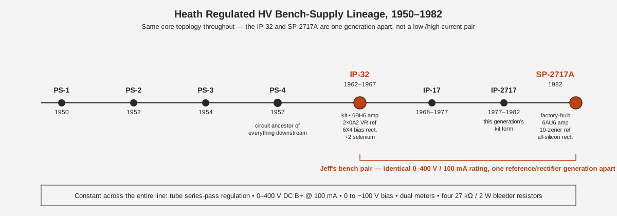
Table 16 — 5.5 Family lineage
| Model | Years | What changed from the prior model |
|---|---|---|
| PS-1 | 1950 | Origin of the line |
| PS-2 | 1952 | — |
| PS-3 | 1954 | — |
| PS-4 | 1957 | The circuit that everything below descends from “with only styling and minor changes” (Eckweiler) |
| IP-32 | 1962–1967 | Kit form; 2×6L6, 6BH6 control amp, 2×0A2 VR reference, 6X4 bias rectifier, +2 selenium rectifiers |
| IP-17 | 1968–1977 | Successor kit generation |
| IP-2717 | 1977–1982 | Direct predecessor of the SP-2717A; still tube rectification + 0A2 reference per the manual’s own circuit-evolution notes |
| SP-2717A | 1982+ | Factory-assembled, Heath-Zenith era; 2×6L6GC, 6AU6 control amp, 10-zener reference, all-silicon rectification |
Full lineage sourcing: Vol 1 §1, citing Eckweiler’s Heathkit of the Month #67, Table I.
6.7 Troubleshooting Quick Table
Symptom-first lookup for the bench. This is a compression of Vol 5’s failure-mode discussion (§3.3 above) plus the circuit reasoning in Vol 2 — treat it as a first-pass triage, not a substitute for reading the schematic before you start swapping parts.
Table 17 — 6. Troubleshooting Quick Table
| Symptom | Most likely cause | How to check | Vol ref |
|---|---|---|---|
| M1 reads 0 V on B+ no matter where B+ VOLTS is set | Shorted 6AU6 (V1) — kills the error amplifier entirely | Pull V1, test/substitute | §3.3 · Vol 2 §3, Vol 5 §1 |
| B+ won’t reach 400 V at full CW | Weak/gassy 6L6GC, or 400 VOLT ADJUST (R14) out of cal | Recalibrate per §3.4 first; if that doesn’t hold, test V2/V3 | §3.4 · Vol 5 §2 |
| B+ reads a nonzero voltage with B+ VOLTS fully CCW | ZERO VOLTAGE ADJUST (R10) out of cal | Re-zero per §3.4 | §3.4 · Vol 5 §2 |
| Regulation drifts, or −150 V/−300 V rails look wrong on a scope | A zener in the ZD1–ZD10 stack has shorted | Check stack voltage in sections; replace the shorted zener and stand the new stack off the board | §3.3 · Vol 5 §1 |
| Excess ripple on B+ | Aged/leaky C2 or C3 (68 µF doubler reservoirs), or a failed D3–D6 | Recap per §3.2; check doubler diodes | §3.2 · Vol 5 §1 |
| C− output won’t reach −100 V, or is noisy | Failed D7–D9, or C4/C5 filter caps aged | Recap the negative supply; check D7–D9 | §3.2 · Vol 5 §1 |
| C− pot feels rough / output erratic near one end | R19 (C− VOLTS pot) partially burned from a prior overload | Check for a burned track; the special-taper pot is a wear item under fault conditions | §1.3, §4 · Vol 5 §1 |
| Mains fuse blows on power-up | Shorted rectifier diode, shorted doubler cap, or a wiring fault | Discharge fully (§3.1) before investigating; do not simply re-fuse and retry | §3.1 · Vol 5 §1 |
| M2 pins or reads far higher than expected for the connected load | Load fault downstream, or B+ VOLTS set higher than intended | Reduce B+ immediately; confirm load wiring before continuing | §2.3 |
| Unit runs but meter lamps (red/amber) don’t track S3 | Lamp or R23/R24 divider fault off filament transformer T2 — cosmetic, not a safety issue | Verify with a meter directly on M1 regardless | Vol 3 §3 |
⚠ Danger — Every row above assumes you have already performed the discharge procedure in §3.1 before opening the case. A fuse blowing, a rectifier shorting, or ripple appearing are all reasons to suspect a fault condition — not reasons to skip verifying the doubler caps are at 0 V before you go looking for it.
6.8 Spares & Consumables Worth Keeping On Hand
A working stock list for this instrument, compiled from the documented failure modes above. Keep these paired with the equivalent IP-32 list where the part numbers diverge.
Table 18 — 7. Spares & Consumables Worth Keeping On Hand
| Item | Why it’s on the list | Typical source |
|---|---|---|
| 6AU6 (spare) | Documented single-point failure for the whole regulator | NOS or current tube retailers |
| 6L6GC × 2 (matched or tested pair, spare) | Wear item under dissipation; readily available new-production | Current-production 6L6GC is common |
| Zener diode stack components (MZ-1000-23 or equivalent) | Documented failure mode; replace as a set if one has failed, since the stack ages together | Semiconductor distributors — verify equivalent part |
| 1N2071 or ~600 PIV equivalent silicon diodes × several | D1–D9 population; cheap insurance | General semiconductor stock |
| 68 µF / ≥450 V electrolytic × 2 | C2/C3 doubler reservoirs — the highest-consequence recap parts on the unit | HV-rated electrolytic sources |
| 22 µF and 47 µF electrolytics (assorted) | C1, C4, C5, C8, C10 | General electrolytic stock |
| 1.5 A slow-blow fuse (110–130 VAC) / 1.0 A (220–260 VAC) | Mains protection — keep both ratings if the unit is ever run on 240 V | Standard fuse stock |
| Insulated HV discharge probe / bleed resistor | Non-negotiable for §3.1 on every service session | Bench safety equipment, not instrument-specific |
6.9 Quick Math — Why 100 mA Is the Real Limit
There is no active current-limit circuit on B+ (§1.3, Vol 2 §3) — the 100 mA continuous / 125 mA intermittent rating exists purely because of pass-tube dissipation. The arithmetic below is an illustrative sanity check, not a manual-published figure — it combines the manual’s own numbers (≈600 V raw doubler rail, 400 V max regulated output, 100 mA rated current) with the 6L6GC’s well-known nominal 30 W anode (plate) dissipation rating, to make concrete why the rating sits where it does and why low-output-voltage, high-current operation is the thermally worst case — not full-output operation.
Table 19 — 8. Quick Math — Why 100 mA Is the Real Limit
| B+ set point | Voltage dropped across the 6L6GC pair (≈600 V raw − set point) | At 100 mA: total pass-tube dissipation | Per tube (assuming even sharing across V2/V3) | Headroom vs. 30 W/tube nominal rating |
|---|---|---|---|---|
| 400 V (max output) | ≈200 V | ≈20 W | ≈10 W | Comfortable |
| 200 V | ≈400 V | ≈40 W | ≈20 W | Getting warm |
| 0 V (min output, e.g. during zero-adjust) | ≈600 V | ≈60 W | ≈30 W | At the nominal per-tube limit |
Read the table’s implication plainly: the worst case for the pass tubes is not full B+ at rated current — it’s low B+ at rated current, because the tubes are dropping nearly the entire raw rail across themselves. This is exactly the situation during the ZERO VOLTAGE ADJUST step of calibration (§3.4, Vol 5 §2) if a load is connected while B+ VOLTS sits near its CCW (0 V) end — a good reason to calibrate with no external load connected, consistent with the recalibration steps in §3.4 (none of which call for a load resistor). It’s also the underlying reason the rating drops from 100 mA continuous to 125 mA only intermittent: continuous full-dissipation operation at the low end of the B+ range is the failure mode the 100 mA figure is protecting against, not an arbitrary round number.
⚠ Danger — This table is a teaching aid, not a substitute for the manual’s rated figures in §1.1. Never use it to justify running the unit outside 100 mA continuous / 125 mA intermittent regardless of the B+ voltage set — M2 is the only thing enforcing the limit in real time, and there is no circuit protection behind it.
6.10 Heath Part Numbers — Quick Order Reference
For ordering NOS or cross-referencing against Heath’s own parts list (Vol 5’s source document). Not a substitute for confirming against the physical parts list in the manual before ordering.
Table 20 — 9. Heath Part Numbers — Quick Order Reference
| Reference | Component | Heath part no. |
|---|---|---|
| M1 | Voltmeter, 0–400/0–150 V dual scale | 407-123 |
| M2 | Milliammeter, 0–150 mA | 407-124 |
| T1 | Power transformer (HV + screen windings) | 54-185 |
| T2 | Filament transformer (6.3/12.6 V + panel AC + meter-lamp reference) | 54-184 |
| Mains fuse (110–130 VAC), 1.5 A slow-blow | Fuse | 421-25 |
| C1 (C1A/C1B), C4, C8, C10 — 22 µF electrolytic | Filter cap | 25-955 |
| C2, C3 — 68 µF electrolytic (B+ doubler reservoirs) | Filter cap | 25-956 |
| C5 — 47 µF electrolytic | Filter cap | 25-957 |
| D1–D9 — silicon diode, 1N2071 | Rectifier | 57-27 |
| ZD1–ZD10 — zener diode, MZ-1000-23 or equivalent | Zener | 56-47 |
| V2, V3 — 6L6GC | Tube | 411-8 |
| R20 — 22 kΩ current-limit resistor | Resistor | 6-225 |
| S1 — AC POWER switch | Switch | 60-24 |
| S2 — DC ON–STANDBY switch | Switch | 61-9 |
Full parts-list context and cross-checks: Vol 3 §2, Vol 5 §1.
6.11 One-Page Summary
Table 21 — 10. One-Page Summary
| Question | Answer | Where the full answer lives |
|---|---|---|
| What does it output? | 0–400 V DC @ 100 mA (125 mA intermittent) B+; 0 to −100 V DC @ 1 mA bias; 6.3/12.6 V AC filament | §1.1 · Vol 1 §1 |
| How does it regulate? | Tube series-pass (2× 6L6GC) driven by a 6AU6 error amp, referenced to a 10-zener stack | §1.5 · Vol 2 |
| What’s inside? | Tube regulator board + solid-state rectifier/reference board, dual meters, two transformers | Vol 3 |
| How do I run it? | Warm up on STANDBY, bring up B+ and C− slowly, watch M2 | §2 · Vol 4 |
| What fails? | Shorted 6AU6, shorted zeners (stand off board), tired 6L6GC, leaky electrolytics | §3.3 · Vol 5 |
| How do I calibrate it? | Mechanical zero → R10 (ZERO) at 0 V → R14 (400 V) at full scale → iterate | §3.4 · Vol 5 §2 |
| Is it dangerous? | Yes — ≈600 V raw, 400 V regulated, LETHAL. No B+ current limit. | §4 · _shared/legal_ethics.md |
| How does it relate to the IP-32? | Same rating, same tube pass element, one generation apart in reference/rectification technology | §5 |
Sources
Primary
- Heath Company, Model SP-2717A Regulated High Voltage Power Supply operation/service manual, part no. 595-2705-02, © 1982, Benton Harbor, Michigan. Specifications, Circuit Description, Recalibration, and Parts List sections. Full text via Internet Archive: https://archive.org/details/Heathkit_SP-2717A_Regulated_HV_Power_Supply
- Bob Eckweiler (AF6C), “Heathkit of the Month #67 — IP-32 Bench HV Power Supply,” Orange County Amateur Radio Club, © 2015 (family lineage Table I; IP-32 circuit detail; bleeder-resistor and selenium-rectifier corroboration): https://www.w6ze.org/Heathkit/Heathkit_067_IP32.pdf
Secondary / corroboration
- Radiomuseum, “Heath (Heathkit) Regulated HV Power Supply IP-2717A”: https://www.radiomuseum.org/r/heath_regulated_hv_power_supply_ip_2717a.html
- Radiomuseum, “Heath (Heathkit) Regulated High Voltage Power Supply IP-2717”: https://www.radiomuseum.org/r/heath_regulated_high_voltage_p.html
- “Heathkit Zenith SP-2717A Power Supply Restore,” Lazy Electrons, 2018-06-02 (documented 6AU6 and zener failure modes, recap voltage-rating choice): https://lazyelectrons.wordpress.com/2018/06/02/heathkit-zenith-sp-2717a-power-supply-restore/