Heathkit TT-1 Tube Tester · Volume 1
Heathkit TT-1 — Vol 1: Overview — What This Tube Tester Is & the Emission-vs-Gm Question
A 5 kHz oscillator, a grid, and a meter reading gain directly in micromhos — the kit-built answer to a question the emission tester can't ask
1.1 The one-sentence definition
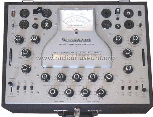
The Heathkit TT-1 is a kit-built, dynamic mutual-conductance (Gm) tube tester — it biases a tube at a realistic DC operating point, injects a small 5 kHz AC signal onto the control grid, and reads the resulting AC plate-current swing directly on a 0–3000 micromho (µmhos) meter scale, which the operator compares against a minimum-acceptable figure printed on the instrument’s own built-in illuminated roll chart. That single sentence is also the answer to the question this whole pair of dives exists to ask: unlike an emission tester, which only asks “is the cathode still emitting?”, the TT-1 asks “how much gain is actually left?” — and it is that second question, not the first, that determines whether a tube will perform in a circuit.
1.2 The emission-vs-Gm question
Jeff keeps two tube testers on the bench on purpose: the Supreme Instruments 385 Automatic (1935), an emission tester, and this Heathkit TT-1 (~1959), a true dynamic Gm tester. They are not redundant — they measure two different things, and the gap between what each one catches is the entire point of owning both. This volume opens with that gap because every other volume in this dive assumes you understand it.
1.2.1 What an emission test does — and what it misses
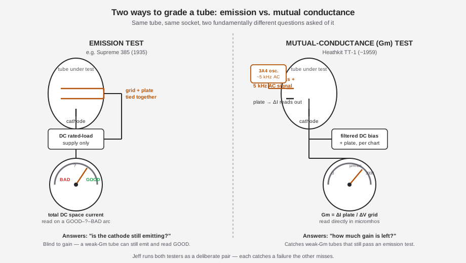
An emission tester like the Supreme 385 (see its own dive, Vol 2 §“How It Works”) ties the tube’s grid and plate together and runs it as a diode-connected emitter under roughly its rated load. A DC ammeter in the plate/cathode circuit reads the total space current the cathode can push through the tube, and the meter face is marked in zones — GOOD, a questionable middle band, BAD — rather than in an engineering unit. It is cheap to build, fast to operate, and close to operator-proof: no bias to set, no signal to inject, just plug in the tube and read the needle against a printed chart.
The catch is in what “total space current” actually measures. It tells you the cathode can still boil off electrons in bulk. It tells you nothing about how that current responds to a small change in grid voltage — which is exactly what determines the tube’s gain in a real circuit. A tube can have a perfectly healthy-looking DC emission current and a collapsed transconductance: enough life left to glow and pass current, not enough left to amplify. That tube reads GOOD on an emission tester and sounds terrible (or dead) in the amplifier it came out of. The 1935 Supreme manual is explicit that this tradeoff was a deliberate engineering choice — it argues against building a mutual-conductance tester on cost and complexity grounds, favoring the simpler, cheaper emission method. That argument is the historical seed of this whole two-tester comparison.
1.2.2 What a mutual-conductance test does
Mutual conductance (transconductance, Gm) is defined as the small-signal ratio
Gm = ΔI(plate) / ΔV(grid) [units: mhos, or micromhos = µmhos = 10⁻⁶ mho]— literally, how much the plate current changes for a small wiggle in grid voltage, at a realistic operating bias. It is the tube parameter that actually sets stage gain (gain ≈ Gm × plate load resistance for a simple resistive stage), so it is the figure of merit that predicts how the tube will behave once it is back in the circuit it came from. To measure it you cannot just apply DC and read a meter — you have to hold the tube at a realistic bias point and then wiggle the grid, which means injecting an AC test signal and reading the resulting AC response. That is a materially harder circuit problem than an emission tester’s DC ammeter, and it is why Gm testers were historically the higher tier of instrument, reserved for better-equipped service benches and factory floors.
The TT-1 solves it with a dedicated 5 kHz oscillator, built around a 3A4 tube, that injects a small, selectable AC signal (2, 1, 0.5, or 0.25 V AC) onto the tube-under-test’s control grid while the tube sits at a properly filtered DC plate voltage (up to 225 V) and DC bias (0–20 V). The resulting AC swing in plate current is picked off, scaled, and displayed directly in micromhos on the meter — not a GOOD/BAD arc, an actual number, which the operator then checks against the minimum-Gm figure printed on the instrument’s own roll chart for that tube type. See the diagram below for the block-level contrast between the two methods; Vol 2 works the TT-1’s circuit in full.
⚠ Danger — mains-powered, HV-adjacent instrument. The TT-1’s plate supply is switch-selectable up to 225 VDC and the panel also carries AC test positions to 177 VAC; accessible chassis points can carry a few hundred volts. This is period-vintage tube gear on a 105–125 V 60 Hz line — treat it with full one-hand-rule / mains-safety discipline per
../_shared/legal_ethics.mdbefore you ever open the case. Refurbishment and safe power-up sequencing are Vol 5’s subject.
1.2.3 Why this matters in practice
A tube that reads “GOOD” on emission but weak on Gm is not a hypothetical — it is the single most common way an emission-only tester misleads a service bench. A power pentode with a partially exhausted cathode coating can still shove plenty of DC current through a diode-connected test load (satisfying the emission tester) while its actual transconductance at the tube’s real operating bias has fallen well below the value the circuit needs for full gain — producing a receiver or amplifier that sounds weak, distorted, or “tired” even though every tube in it just tested GOOD. The Gm tester exists specifically to close that gap. It is also not infallible in the other direction — see the honest limits called out below — which is exactly why the two-tester comparison in Vol 6 is worth having rather than declaring one method categorically “better.”
What the Gm test does not catch, so this volume doesn’t oversell it: it measures small-signal Gm at one fixed bench operating point, not the tube’s behavior at full rated power dissipation, so a marginal power tube can still read acceptable Gm on the bench and fail under real load. It tests one element/section at a time — the operator has to re-set the P/G/K bus switches to check each triode of a dual triode separately. And it does not directly reveal microphonics, high-frequency rolloff, or intermittent faults; the number it reports still requires the operator to interpret it against the chart minimum. Vol 2 §“Limits of the method” goes deeper on all three.
1.3 What this unit is NOT
Worth nailing down before the specifics, because a few wrong mental models attach easily to “vintage Heathkit tube tester”:
- Not an emission tester. Heath built its own emission-tester line separately — the TC-1, TC-2, TC-3, and later the IT-series (e.g. IT-3117/IT-11). Those tie grid and plate together and read total DC space current on a GOOD/BAD scale, exactly like the Supreme 385. The TT-1 is a categorically different, dynamic Gm instrument; if a Heath catalog page or eBay listing says “tube tester” without specifying the method, it is worth checking which family it belongs to before assuming it behaves like this one.
- Not a two-piece instrument with a separate roll-chart drawer. As covered below, the illuminated roll chart lives in the main panel. There is no second box to keep track of, and no drawer to lose.
- Not a later circuit revision when it says “TT-1A.” Covered in full below — the “A” designates a bolt-on socket adapter, not a redesigned tester.
- Not selenium-rectified. Some tube-era gear from this period leans on selenium rectifier stacks that are a known aging/odor/fire hazard; the TT-1’s plate and bias supplies use silicon rectifiers (Heath part CR-101) instead. Vol 5 covers the actual known failure mode of those silicon parts, which is a different (and simpler) problem.
- Not a curve tracer. A curve tracer (see the hub’s Curve Tracers Overview) plots a full family of plate-current-vs-plate-voltage curves across a swept range; the TT-1 reports a single Gm number at one operating point per test. Related purpose — characterizing tube health — very different instrument and workflow.
1.4 What this unit is, specifically
Having established why a Gm tester exists, the rest of this volume is about the TT-1 as a specific, real instrument: who built it, when, and where it sits in Heath’s own product line.
1.4.1 Headline facts
Table 1 — Headline facts
| Parameter | Value | Notes |
|---|---|---|
| Model | Heathkit TT-1 “Mutual Conductance Tube Tester” | TT-1A = TT-1 + TTA-1-1 socket adapter, see below |
| Maker | Heath Company, Benton Harbor, Michigan | Sold as a solder-it-yourself kit |
| Introduced | circa 1959–1960 | One source says “circa 1959”; RadioMuseum lists “1960 ?” |
| Production span | Catalog presence until ~1973; tube-data supplement sheets issued through November 1978 | A given unit could have been built anywhere across that span |
| Test method | Dynamic mutual conductance (Gm), AC grid-signal method | NOT emission — see Heath’s own TC-1/TC-2/TC-3 line for that |
| Gm reading | 0–3000 µmhos direct, multipliers to ~24,000 µmhos | Compared to a minimum figure on the built-in roll chart |
| Test signal | 5 kHz, selectable 2 / 1 / 0.5 / 0.25 V AC, from a 3A4 oscillator | Distinct from Hickok-style testers, which derive signal from the 60 Hz line |
| Plate supply | Filtered DC, switch-selectable 26 / 90 / 135 / 225 V; AC positions 20/45/177 V; variable DC for VR test | See Vol 2 for the full supply table |
| Bias supply | Filtered DC, 0–20 V, two ranges | Front-panel BIAS pot + internal adjust |
| Rectifiers | Silicon (Heath part CR-101) | Not selenium — a common misconception for gear of this era |
| Other tests | Shorts/leakage (0–10 MΩ), grid current/gas (¼ µA, via a 12AV6), life test (heater −10%), VR-tube test, diode O.K./Reject | Full detail in §“Also does” below and Vol 2 |
| Calibration | Self-calibrating — built-in CALIBRATE switch (BIAS/SIGNAL/METER) | No reference tube or external test gear needed |
| Sockets, built-in | 4-, 5-, 6-, 7-pin (large, miniature, sub-miniature), 8-pin sub-min, octal, loctal, 9-pin miniature, plus blanks | TT-1A adapter adds 12-pin Compactron + Nuvistor |
| Instrument tubes | 3A4 (oscillator), 12AV6 (grid-current detector) | The only two active devices in the whole instrument |
| Physical | ~17.75–18 × 13.5 × 7.5–8.5 in, wood/covered carrying case | Portable; AC line powered, 105–125 V 60 Hz |
| Lineage | Kit redesign of the Weston Model 981 (Type 3 / 981-3) | Daystrom owned both Weston and Heath — see below |
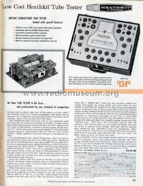
| Original kit price | Not found in any period catalog located during research | A period catalog ad shows $134.50 — see below, cited as a period-catalog figure only, not confirmed as the original 1959 introductory price |
1.4.2 Maker, era, and the $134.50 catalog ad
Heath Company built the TT-1 in Benton Harbor, Michigan, as a kit — the buyer bought a box of parts, a step-by-step assembly manual, and soldered it together themselves, in keeping with Heath’s whole business model across test equipment, radios, and amateur gear through the 1950s–70s. The best synthesis of the introduction date, cross-checking a “circa 1959” source against RadioMuseum’s “1960 ?” listing, is that the kit was released around 1959–1960. It stayed in Heath’s line for well over a decade: it is gone from catalogs by roughly 1973, but Heath kept issuing periodic tube-data supplement sheets for it as late as November 1978, which means a given surviving unit could have been assembled anywhere from the late 1950s into the early 1970s depending on when the original buyer bought the kit.
No period catalog price for the original TT-1 kit was located in the primary sources for this dive — the commonly-seen ”~$499” figure attached to some listings is a modern resale price, not a 1959 kit price, and this dive does not repeat it as though it were. What is verified is a period Heath catalog advertisement, titled “Low Cost Heathkit Tube Tester,” pictured below, which shows the TT-1 with a visible catalog price of $134.50. That figure is cited here strictly as what one period catalog ad shows, not confirmed as the original introductory price — treat it as a data point, not a settled fact.
1.4.3 Lineage — a Weston professional instrument, redesigned into a kit
The TT-1 did not start life as a Heath design from scratch. It is a kit-form redesign of the Weston Model 981 (Type 3 / 981-3), a professional-grade mutual-conductance tester that Weston Electrical Instrument Corp. had been building since 1957. The connection is corporate, not coincidental: Daystrom Inc. owned both Weston and Heath Company concurrently in the late 1950s, and had the 981-3 circuit reworked into solder-it-yourself kit form and cosmetically restyled for the Heathkit line. Collectors who have handled both instruments describe the TT-1A variant in particular as “an almost exact copy of the Weston 981.” No clean standalone photo of the Weston 981-3 was sourced for this dive — its role here is described in text, and its own testing philosophy, front-panel layout, and any circuit differences from the TT-1 are Vol 3’s subject, not this overview’s.
This lineage matters for two practical reasons beyond trivia. First, it explains why the TT-1 is unusually capable for a kit-built instrument — it inherited a professional circuit rather than being value-engineered down from one. Second, it means Weston 981-3 setup/chart data is largely interchangeable with TT-1 roll-chart data for plate, bias, meter, and signal settings — useful if a TT-1’s own roll chart or supplement sheets are ever missing for a given tube type (Vol 4 covers this).
1.5 Also does — beyond the headline Gm test
The Gm reading is the reason the instrument exists, but the TT-1’s panel carries five other distinct test functions built around the same chassis, sharing the socket bank and the roll chart. Vol 2 explains how each one works circuit-wise; this is the summary for orientation.
Table 2 — Also does — beyond the headline Gm test
| Function | What it checks | Method | Spec |
|---|---|---|---|
| Shorts / leakage | Element-to-element shorts or leakage inside the tube | Direct-reading leakage ohmmeter across 5 selectable pin pairs (LEAKAGE switch) | 0–10 MΩ |
| Grid current / gas | Gas or grid emission (ionization current at the grid) | A 12AV6 used as a sensitive grid-current detector | ¼ µA sensitivity |
| Life test | Whether a tube’s Gm holds up under a stressed heater | Momentary switch drops heater voltage ~10%; watch the Gm meter droop | — |
| Diode / rectifier test | Basic go/no-go on diode and rectifier tubes | Meter zone marked “DIODES O.K.” vs. reject | Emission-style pass/fail |
| VR-tube test | Regulation quality of gas voltage-regulator tubes | Variable DC supply (PLATE position G), meter reads voltage directly | 0–200 V |
Beyond that table, the TT-1 also has provisions for low-power thyratrons and electron-ray “magic eye” indicator tubes, a “hybrid”/auto-radio series-heater accommodation, and a 26 V space-charge-grid supply for space-charge tubes — a broad footprint for a kit instrument, again traceable to the Weston 981-3 lineage it descends from.
1.6 Setup at a glance — the built-in roll chart
One correction worth making plainly, because it is easy to assume otherwise from photos of similar-era testers: the TT-1 does not have a separate roll-chart drawer or a second physical unit. The illuminated, constant-tension roll chart is built directly into the main instrument panel, driven by a thumb-wheel at each side of the chart window, visible in the front-panel photo above and in close-up in Vol 3/Vol 4. There is also no single “Automatic” tube-selector knob of the kind the Supreme 385 uses — instead, the operator scrolls the chart to the tube type, then sets a bank of individual rotary per-pin selector switches (one per socket pin — top row pins 1–5, bottom row pins 6–9) plus P/G/K bus switches to route the correct socket pins to plate, grid, and cathode for the section under test, following the codes printed on the chart. Vol 3 covers the hardware in full and Vol 4 walks the complete operating sequence.
1.6.1 Front-panel controls at a glance
The operating sequence (Vol 4’s full subject) touches most of these controls in order; this table is purely an orientation index to what is on the panel and what each control is for.
Table 3 — Front-panel controls at a glance
| Control | Function |
|---|---|
| SET LINE | Continuously variable line-voltage adjustment, checked against a LINE CHECK/LINE TEST meter position |
| FILAMENT | Heater voltage/current selector, including the constant-current 300/450/600 mA series-string positions |
| PLATE (A–G) | Plate voltage/mode selector — DC positions 26/90/135/225 V, AC positions 20/45/177 V, variable DC (position G) for VR test |
| BIAS RANGE (L/H) + BIAS pot | Selects the low or high bias range, then dials in the exact DC bias voltage |
| SIGNAL | Selects the AC test-signal amplitude fed to the grid: 2 / 1 / 0.5 / 0.25 V |
| METER | Sets meter sensitivity/multiplier for the Gm reading |
| LEAKAGE | Selects which pin-pair the leakage ohmmeter checks (5 positions) |
| DISCONNECT | Isolates elements not under test |
| LIFE TEST | Momentary heater-voltage-droop switch |
| GRID CURRENT | Engages the 12AV6 grid-current/gas detector |
| Gm test lever | Engages the actual mutual-conductance measurement |
| CALIBRATE | Self-calibration switch, positions for BIAS / SIGNAL / METER |
| Per-pin selector bank + P/G/K bus switches | Routes socket pins to plate/grid/cathode per the roll-chart code for the tube under test |
1.7 Emission vs. Gm — head-to-head
This table is the short version of the comparison Vol 6 develops in full, framed around the two specific instruments in Jeff’s pairing.
Table 4 — Emission vs. Gm — head-to-head
| Emission test (Supreme 385, 1935) | Mutual-conductance test (Heathkit TT-1, ~1959) | |
|---|---|---|
| What it measures | Total DC space/cathode current, diode-connected | AC plate-current response to a small AC grid signal — actual transconductance |
| Reading | GOOD / questionable / BAD zone on a meter arc | Direct numeric value, 0–3000+ µmhos, checked against a chart minimum |
| Test signal | None — pure DC, rated-load condition | Dedicated 5 kHz AC signal from a 3A4 oscillator, selectable amplitude |
| Bias realism | Tube run diode-connected, not at its real operating bias | Tube held at a realistic filtered DC plate voltage and bias per the chart |
| Catches | Fully exhausted / dead cathodes, gross shorts (with add-on leakage check) | Weak-Gm tubes that still emit fine — the emission tester’s blind spot |
| Misses | Reduced transconductance in a tube that still emits current | Full-power/high-dissipation behavior; still only a small-signal snapshot |
| Setup complexity | Single rotary selector (on the 385’s “Automatic” design) | Roll chart + per-pin selector bank + P/G/K bus switches — more operator steps |
| Calibration | Mechanical zero/full-scale check | Fully self-contained CALIBRATE switch — no reference tube needed |
| Era / tier | 1935, cheap, fast, operator-proof, broad service-bench tool | ~1959, Heath’s top-of-line kit tester, closer to a lab/service-grade Hickok or Weston |
| Historical stance | The 1935 Supreme manual argues against building a Gm tester, on cost/complexity grounds | Built specifically to answer the question emission testing can’t |
1.8 TT-1 vs. TT-1A — one adapter, not a new instrument
Because the “A” suffix on Heathkit models often does signal a circuit revision, it is worth flagging plainly here that it does not in this case. A TT-1A is a TT-1 with the TTA-1-1 tube-socket adapter added — a small accessory, introduced around 1962, that bolts in (typically mounted in the case lid) and adds a 12-pin Compactron socket and a Nuvistor socket, wired into the existing selector-switch bus with only minor supporting wiring changes. There is essentially no performance or core-circuit difference between a bare TT-1 and a TT-1A — the “A” just means “TT-1, plus the adapter that lets it also test tube families introduced after the base kit was designed.” Vol 3 covers the adapter’s physical installation and socket-pinout details for anyone with one to fit.
1.9 Where it sits on Jeff’s bench
Jeff owns two tube testers as a deliberate pair, and this instrument is the newer, more capable half of that pair:
Table 5 — Jeff owns two tube testers as a deliberate pair, and this instrument is the newer, more capable half of that pair
| Instrument | Era | Method | Role on the bench |
|---|---|---|---|
| Supreme Instruments 385 Automatic | 1935 | Emission | Fast first-pass sort: dead vs. plausibly-alive |
| Heathkit TT-1 (this instrument) | ~1959–60 | Mutual conductance (Gm) | The real verdict on gain — catches what the 385 can’t see |
Run in sequence, the two testers cover each other’s blind spot: an emission-BAD tube is dead and needs no further test; an emission-GOOD tube still deserves a Gm check before it goes back into a circuit that depends on its gain. Vol 6’s cheatsheet works this two-tester workflow in full, including a side-by-side reading interpretation guide for tubes that disagree between the two methods.
1.10 Ownership status
Status: Owned. Jeff has a TT-1 on the bench; unit-level details — serial number, whether it carries the TTA-1-1 adapter (making it functionally a TT-1A), condition, and refurbishment history — are tracked in the shared MY_GEAR inventory under slug heathkit-tt-1-tube-tester and are TBD pending photography and registration. The FIGURE SLOT above awaits Jeff’s own bench photo of the unit; Vol 5’s recap and rectifier-service photography likewise awaits his hands-on refurbishment work.
1.11 Depth index — where each volume takes you
This volume is the on-ramp. The rest of the dive goes deep on one facet each.
Table 6 — Depth index — where each volume takes you
| Vol | Title / focus | Reach for it when… |
|---|---|---|
| 1 | Overview — What This Tube Tester Is & the Emission-vs-Gm Question (this volume) | You need the framing, the headline facts, and the Weston lineage |
| 2 | How It Works — The Test Method & Circuit | You want the 5 kHz oscillator, the bias/plate supply chain, the µmhos scaling math, and the honest limits of the Gm method |
| 3 | Inside This Unit — Hardware, Meter, Sockets & Setup | You want the chassis, the meter movement, the socket bank, the TTA-1-1 adapter’s physical fit, and the built-in roll chart mechanism |
| 4 | Using It — Setting Up & Grading a Tube | You have a tube in hand and want the full chart-to-meter operating sequence |
| 5 | Refurbishing & Calibration | You’re recapping, replacing the CR-101 rectifiers, dealing with the AC filament-current capacitor, or running the self-calibration procedure |
| 6 | Cheatsheet & Emission vs Gm — the Two-Tester Bench | You want the one-page bring-up reference and the full side-by-side workflow against the Supreme 385 |
Read Vol 2 next for the circuit-level “how” behind the µmhos reading — the 5 kHz oscillator, the plate/bias supply chain, and exactly how an AC grid signal turns into a number on the meter.
Sources
Primary / manuals / schematics:
- Heathkit TT-1 Operation/Assembly manual (OCR), rsp-italy.it mirror: https://www.rsp-italy.it/Electronics/Kits/_contents/Heathkit/Kits/Heathkit%20TT-1%20Tube%20tester%20Manual.pdf
- Internet Archive — Heathkit TT-1 Gm Tube Tester: https://archive.org/details/Heathkit_TT-1_Gm_Tube_Tester
- Internet Archive — Heathkit TT-1A schematic: https://archive.org/details/Heathkit_TT-1A_Tube_Tester_schematic
- Internet Archive — Heathkit TT-1A (TTA-1-1 socket-adapter assembly manual, 8-29-69): https://archive.org/details/Heathkit_TT-1A_Tube_Tester
- Internet Archive — Heathkit TT-1 Tube Tester data: https://archive.org/details/Heathkit_TT-1_Tube_Tester_data
- Tube-data supplement (November 1978): https://www.pestingers.net/pdfs/heathkit-test/t1a-supplemental-78.pdf
Hands-on refurbishment (primary, detailed):
- Kent Nickerson, “Refurbishment and Verification of the Heathkit TT-1 Tube Tester”: https://paulcarbone.com/blog/wp-content/uploads/2020/06/TT1_Refurbishment.pdf
Museum / reference:
- Heathkit Virtual Museum — TT-1: https://heathkit-museum.com/test/hkTT-1.html
- RadioMuseum — Heath Tube Tester TT-1: https://www.radiomuseum.org/r/heath_tube_tester_tt_1_tt.html
- Alan Douglas, Tube Testers and Classic Electronic Test Gear (ISBN 1886606145)
- RDF Products application note VR_APL_004 (TT-1A chassis figures): http://www.rdfproducts.com/vr_apl_004.pdf
Weston lineage:
- Weston 981: http://www.vacuumtubes.com/981.html
- Weston 981 Type 3: https://vintagetubeelectronics.com/weston-981-type-3-tube-tester/
- Weston 981-3 vs. Heathkit TT-1 discussion (Daystrom/Weston→Heath): https://rec.antiques.radio-phono.narkive.com/idZqSxCH/weston-981-3-vs-heathkit-tt-1-tube-testers