Heathkit TT-1 Tube Tester · Volume 2
Heathkit TT-1 — Vol 2: How It Works — The Test Method & Circuit
Two tubes, five kilohertz, and a roll chart — how a 1959 kit instrument turns a grid signal into a transconductance reading in micromhos.
2.1 Why This Volume Exists
Vol 1 laid out the emission-vs-Gm question that motivates keeping this instrument next to the Supreme 385 on the bench. This volume answers the question a schematic asks: how, exactly, does the TT-1 turn a tube into a number on a meter face, and why is that number trustworthy in a way an emission reading isn’t? Every voltage, tube type, and switch position below is drawn from the TT-1 operation/assembly manual, the Heathkit-museum and RadioMuseum listings, and Kent Nickerson’s hands-on refurbishment report — see Sources. Where a claim rests on a single secondary source rather than the manual itself, that is said plainly in the prose rather than hedged with a tag.
⚠ Danger — Everything in this volume describes a mains-powered instrument with internal DC as high as 225 V and momentary transients well above that at the plate supply’s unloaded terminals. The TT-1 has no mains-isolation transformer of its own; treat the chassis as line-connected until proven otherwise with a meter, and follow the one-hand rule and the bleed-before-you-reach discipline in
_shared/legal_ethics.mdany time the case is open. This volume is theory-of-operation, not a repair walkthrough — refurbishment procedure is Vol 5.
2.2 The Method in One Sentence, Then Slowly
The TT-1 biases a tube at a realistic operating point, injects a small known AC signal onto its control grid, and reads the AC swing that signal produces in the plate current — scaled directly in micromhos (µmhos) of transconductance. That is a genuine measurement of gain. It is categorically different from what Heath’s own emission testers (the TC-1, TC-2, TC-3, and later IT-series like the IT-3117/IT-11) do, and it is different from what the sibling instrument in this pair — the 1930s Supreme Instruments 385 — does.
2.2.1 What “Mutual Conductance” Means, Mechanically
Mutual conductance (transconductance, symbol g_m) is the ratio of a small change in plate current to the small change in grid voltage that caused it, with plate voltage held constant:
g_m = ΔI_plate / ΔV_grid (at constant V_plate)Units are siemens (mhos), and because tube g_m figures are small, the practical unit is the micromho (µmho = 10⁻⁶ mho — numerically identical to the modern µS, microsiemens, just older nomenclature). A healthy small-signal audio pentode might read on the order of 1,000–6,000 µmhos; a weak one droops toward the roll chart’s reject line long before its cathode has stopped emitting current altogether. That gap — a tube that still emits current but no longer amplifies well — is exactly what an emission tester cannot see and a Gm tester can, and it is the throughline of this whole pair of dives (Vol 1’s emission-vs-Gm framing; Vol 6 revisits it as the two-tester bench workflow).
2.2.2 The Four Quantities the TT-1 Must Supply to Make That Measurement Mean Anything
A transconductance figure is only meaningful at a stated operating point. Yank a tube’s plate voltage or grid bias away from where the tube normally lives and its g_m changes — sometimes by a large factor, because g_m is a nonlinear function of both. So before the TT-1 measures anything, it has to establish an operating point that resembles the tube’s real working condition. That takes four independently-set supplies, each described in its own section below:
Table 1 — each described in its own section below
| # | Supply | What it sets | Range | Where covered |
|---|---|---|---|---|
| 1 | Heater / filament | Cathode temperature — everything else is meaningless if this is wrong | rated V, or 300/450/600 mA constant-current | §3.1 below |
| 2 | Plate | The DC operating plate voltage | 26 / 90 / 135 / 225 VDC (switch positions O/C/D/F) | §3.2 below |
| 3 | Bias | The DC grid bias that sets the quiescent operating current | 0–20 V DC, two ranges (L/H) | §3.3 below |
| 4 | Signal | The small AC test signal riding on top of the bias | 2 / 1 / 0.5 / 0.25 V AC | §4 below |
Once 1–3 are dialed in per the roll chart, the fourth is what actually produces the measurement — the oscillator injects a known AC voltage, the tube’s transconductance converts it to an AC plate-current swing, and the meter reads that swing scaled to µmhos (§5).
2.3 Establishing the Operating Point
2.3.1 Heater / Filament Supply
The heater has to run at the tube’s rated voltage (or, for series-string tubes designed to run on constant current rather than constant voltage, at its rated current) or nothing downstream means anything — a starved cathode reads low on every other test regardless of the tube’s real health, and an overdriven one reads falsely high and can shorten what life the tube has left.
The FILAMENT switch selects the rated heater voltage for the tube under test from the roll chart. A second, less common mode exists for series-string tubes — the ones designed to be wired filament-to-filament across the AC line in television and radio chassis, which are rated in constant heater current (150 mA, 300 mA, and similar) rather than constant voltage. For these, the TT-1 can supply constant-current outputs of 300, 450, or 600 mA, set by a three-section AC capacitor (~3.6 µF / 3.6 µF / 7.1 µF at 125 VAC) in series with the heater winding rather than by direct voltage selection — capacitive reactance, not a resistor, sets the current, so the current stays roughly constant even as the tube’s own heater resistance changes with temperature as it warms. Heath advertised this as a future-proofing feature at a time when television receiver designs using series heater strings were common.
⚠ Danger / reliability note — This AC filament capacitor is the single most failure-prone component in the whole instrument. As the dielectric ages the capacitance can rise — sometimes triple its rated value — which raises the constant-current output well above the intended 300/450/600 mA and can overheat or physically bulge the tube’s heater and the cap itself. Kent Nickerson’s refurbishment report describes simply disconnecting this capacitor on his unit, on the reasoning that few tubes anyone tests today actually need the current-drive heater modes; if it’s kept in service, only an AC-rated (≥150 VAC) polystyrene film capacitor is an acceptable replacement — never a DC-rated part in an AC current-setting role. Full procedure is Vol 5’s recap section.
The LIFE TEST function (§7.3) borrows this same heater supply and drops it by roughly 10% momentarily, independent of the constant-current modes — a health check layered on top of normal operation rather than a separate supply.
2.3.2 Plate Supply
The plate supply is filtered DC, switch-selectable to match the tube’s rated plate voltage from the roll chart:
Table 2 — chart
| PLATE switch position | Output | Notes |
|---|---|---|
| A | 20 VAC | unrectified AC test position |
| B | 45 VAC | unrectified AC test position |
| C | 90 VDC | filtered DC |
| D | 135 VDC | filtered DC |
| E | 177 VAC | unrectified AC test position |
| F | 225 VDC | filtered DC |
| G | variable DC, 0–200 V (metered) | used for the VR-tube regulation test, §7.4 |
| O | 26 VDC | filtered DC, lowest range (also the space-charge supply position for space-charge tubes) |
The AC positions (A/B/E) exist for tests where the manual’s verification procedure checks raw transformer output rather than the filtered Gm-test rails; the day-to-day Gm test itself always runs from one of the filtered DC positions (O/C/D/F).
The filtered DC comes off a bank of electrolytic filter capacitors — three 20 µF at 350 V plus a 40 µF at 150 V section, by the manual’s parts list — fed by silicon rectifier diodes, Heath’s own part number CR-101. This is worth stating plainly because it corrects a plausible but wrong assumption: this is not a selenium-rectifier supply. Selenium stacks were common in Heathkit-era gear of this vintage and age into a known, smelly failure mode (Vol 5 covers selenium as a general hazard note), but the TT-1’s plate and bias supplies are silicon from the factory. The CR-101 diodes themselves are not especially rugged by modern standards — a small silicon junction rated for roughly 0.45 V forward drop at 1 mA is not a generously-derated part — and they are a common refurbishment casualty (Vol 5), but the technology is silicon, not selenium.
One AC-signal-path rectifier remains genuinely unconfirmed. Recovering a 5 kHz AC plate-current swing as a DC meter deflection implies some small rectifier in the meter circuit itself (copper-oxide, germanium, or selenium instrument type would all have been plausible choices in 1959). One forum aside claims “a selenium bridge inside the meter” on some units, but this has not been checked against the schematic and should be treated as an open question rather than a fact — if a meter-path rectifier turns out to be selenium, it would be the one place selenium legitimately appears in this instrument’s signal path.
Protection note. A common casualty during refurbishment or field use is a burned-out R20 — a resistor commonly cited in refurbishment reports as the thing that sacrifices itself when a badly shorted tube is pushed straight into a biased test without a leakage check first (§7.2 covers the leakage test itself); its exact function and location in the circuit weren’t confirmed against the schematic for this dive. The instrument has no fused, current-limited protection specifically ahead of the plate supply beyond this resistor and the main line fuse, so “leakage before Gm” is not just good practice — it is the difference between a tube failing safely and a resistor failing instead.
2.3.3 Bias Supply
The bias supply is filtered DC, 0–20 V, negative-going (grid bias), with two ranges (L/H) selected by the BIAS RANGE switch and a front-panel BIAS potentiometer for fine adjustment within the selected range. An internal trimmer (documented in the manual as a “CD adjust”) sets the supply’s absolute calibration, checked and reset via the CALIBRATE switch’s BIAS position (§9) rather than against an external reference.
Setting bias correctly matters more than it might look on the surface: transconductance is a derivative of the plate-current-vs-grid-voltage curve, and that curve is not a straight line. A tube biased even slightly off the chart’s intended point will show a different g_m than the same tube biased correctly — sometimes enough to shift a marginal-but-good tube across the roll chart’s reject line in either direction. This is part of why the roll chart specifies plate, bias, filament, and signal level together as one package per tube type rather than leaving any of them to operator judgment.
2.4 The 5 kHz Oscillator and the AC Grid Signal
2.4.1 A Dedicated Oscillator, Not a Line-Frequency Tap
This is the design decision that separates the TT-1’s whole family (and its parent, the Weston 981-3) from the other major school of dynamic mutual-conductance testers on the used market. Hickok-style testers derive their AC test signal from a tap on the 60 Hz power line itself, filtered and scaled down to test-signal levels. It’s a cheap, simple, and time-tested approach. The TT-1 instead builds a dedicated internal oscillator running at roughly 5 kHz, centered on a single tube:
- Tube: a 3A4 — a miniature pentode/power-amplifier tube from the battery-portable-radio family, repurposed here purely as the instrument’s own signal source. It is one of only two active devices in the entire instrument that are not the tube under test (the other is the 12AV6 grid-current detector, §7.1).
- Frequency-setting component: a 0.02 µF, 600 V capacitor sets the nominal oscillation frequency. Nickerson measured the actual frequency on his own unit at roughly 7 kHz rather than a clean 5 kHz — component drift over six decades is unsurprising in a single RC/RLC-timed oscillator, and the self- calibration procedure (§9) is explicitly built to absorb exactly this kind of drift rather than requiring the frequency to be dead-on.
- Signal levels: the SIGNAL switch selects 2, 1, 0.5, or 0.25 V AC as the calibrated grid-drive amplitude, per the roll chart’s specification for the tube under test. Smaller-signal tubes and tubes with steep transfer curves get a smaller test signal so the measurement stays in the tube’s small-signal (roughly linear) region rather than sliding into visible curvature or clipping.
Why does frequency choice matter enough to be a headline design decision rather than an implementation detail? A signal derived from the 60 Hz line is convenient — no extra active stage needed — but it also means the test signal is exactly the same frequency (and often, without careful design, correlated in phase) as every other 60 Hz artifact already present in a mains-powered instrument: supply ripple, transformer hum pickup, and stray coupling through the tube socket wiring. A test signal at 5 kHz sits well clear of that noise floor, in principle making a small, weak transconductance signal easier to distinguish cleanly from AC line junk riding on the same wiring — and it lets the meter’s own coupling/filter capacitors be sized specifically for that frequency, rather than doing double duty rejecting 60 Hz supply artifacts and passing a 60 Hz test signal at the same time. Whether the TT-1’s execution of that idea is as clean as the principle suggests is the subject of the next section.
2.4.2 The Honest Quirk: a 60 Hz Rider on the 5 kHz Signal
Enthusiast writeups of the TT-1 (rather than the factory manual itself) describe a specific, testable oddity: the 3A4 oscillator’s own supply is not fully rectified and filtered, so a 60 Hz component rides on top of the nominal 5 kHz test signal actually delivered to the grid. The meter’s own detection/reading circuit is tuned or filtered enough to respond primarily to the 5 kHz component — so the reading is not directly corrupted by the ripple — but the tube under test is, strictly speaking, being exercised with a composite two-frequency signal rather than a clean 5 kHz tone.
Some who have looked at this describe it as arguably intentional — a more “real-world,” slightly messier stress on the tube than a laboratory-clean single tone would be, on the theory that real service conditions are never perfectly clean either. That reading is plausible but is enthusiast interpretation, not something stated in the factory documentation reviewed for this dive, and it should be treated as a design note rather than a confirmed engineering rationale. What is well corroborated is the underlying physical description — an unrectified or lightly-filtered oscillator supply riding 60 Hz onto the 5 kHz carrier — which several independent forum and collector sources describe consistently. Practically, for a bench-service instrument whose whole purpose is a comparative pass/fail reading against a printed chart minimum rather than a laboratory-grade absolute transconductance figure, a small residual 60 Hz component is unlikely to move a tube meaningfully across the reject line — but it is worth knowing about before treating any single TT-1 Gm reading as a metrology-grade number.
2.4.3 TT-1 vs. Hickok: a Genuine Design Fork, Not a Quality Gap
It is worth being precise about what the 5-kHz-vs-60-Hz distinction does and does not imply. It is not that one approach is simply “better engineered” than the other — both are legitimate ways to build a dynamic mutual-conductance tester, and both were commercially successful for decades. The distinction is a design fork inherited from the TT-1’s parent instrument:
Table 3 — fork inherited from the TT-1's parent instrument
| TT-1 / Weston 981 lineage | Hickok-style dynamic testers | |
|---|---|---|
| Test-signal source | Dedicated internal oscillator (3A4), ~5 kHz | Tap on the 60 Hz power line |
| Extra active stage needed | Yes — one tube (3A4) purely for signal generation | No — signal derived passively from the line |
| Test signal isolated from line-frequency artifacts | In principle, yes (different frequency) | No — test signal and line hum share a frequency |
| Known quirk | Unfiltered oscillator supply lets 60 Hz ride on the 5 kHz tone | N/A (signal is 60 Hz by design) |
| Commercial pedigree | Weston 981-3 (1957) → Heathkit TT-1 (~1959) | Hickok’s long-running Cardmatic/dynamic-tester line |
The narkive/Antique Radio Forums discussion of “Weston 981-3 vs. Heathkit TT-1 tube testers” is where this 5-kHz-vs-60-Hz framing is corroborated outside the manual itself; it’s consistent with the manual’s own identification of the 3A4 as an oscillator tube and with the frequency-setting capacitor in the parts list.
2.5 Reading the Number: From ΔIp to µmhos on the Meter Face
2.5.1 What the Meter Is Actually Doing
With the tube biased at its operating point (§3) and the SIGNAL switch selecting a known AC grid-drive amplitude (§4), the tube’s own transconductance converts that AC grid voltage into an AC plate-current swing riding on top of the tube’s steady DC plate current. The TT-1’s Gm circuit picks off that AC component — rejecting the much larger steady DC plate current, which is not what’s being measured — and scales it so the panel meter reads out directly in µmhos, on a primary 0–3000 µmhos scale extendable with multipliers to roughly 24,000 µmhos for high-transconductance power and sweep tubes. This directness is worth pausing on: the meter is not showing a raw AC voltage that the operator has to convert with a formula on the fly — the SIGNAL-level selection, the internal scaling resistors, and the meter’s own calibration (§9) are all set up so that once the tube is biased per the chart and the Gm lever is pressed, the needle position is the transconductance figure, in the standard unit, full stop.
2.5.2 Comparing Against the Roll Chart
A raw Gm number by itself does not say GOOD or BAD — it says a magnitude, and different tube types have wildly different “normal” transconductances (a small-signal pentode and a high-power beam tetrode are not on the same scale). The illuminated roll chart (built into the panel — see Vol 3’s hardware section for the mechanism itself) carries, for each tube type, a printed minimum acceptable Gm figure alongside the plate/bias/filament/signal setup data. The operator’s job after taking the reading is simply to compare the needle position against that printed minimum: at or above it, the tube passes; below it, the tube is weak or bad. This is what makes the instrument usable by a service technician without requiring them to carry tube-curve reference data in their head — all of that judgment is pre-baked into the chart. Vol 4’s walkthrough covers the full scroll-chart-then-dial-in operator sequence in procedural terms.
2.5.3 The “Needs a Little Arithmetic” Caveat
One secondary source in the research for this dive — Alan Douglas’s book on tube testers and classic test gear — notes that getting a fully corrected Gm figure out of a TT-1-family reading can require a small amount of arithmetic on the operator’s part, beyond simply reading the needle position. The specifics of that correction (what it accounts for, and under what conditions it matters) were not recovered from the sources available for this dive, and this note rests on a single author’s published observation rather than being cross-confirmed against the factory manual. It is included here because it is a reasonable thing to flag rather than omit, but should not be treated as a fully specified procedure — if a future refurbishment or calibration session (Vol 5) turns up the manual’s own language on this point, it supersedes this note.
2.6 What the Gm Test Catches — and What It Doesn’t
2.6.1 Against the Emission-Only Alternative
This is the comparison that gives the two-tester bench (this instrument alongside the Supreme 385, Vol 6) its whole reason to exist. An emission test — the Supreme 385’s method, and the method behind Heath’s own TC-series — ties the tube’s elements together into a simple diode connection, runs it under something close to rated load, and reads total DC space current on a scale that’s ultimately just measuring “is the cathode still emitting electrons at a useful rate.” That is a fast, cheap, largely operator-proof test, and it does catch the most common tube failure mode (a cathode that has genuinely worn out). What it cannot see is a tube whose cathode still emits plenty of current in that simple diode connection, but whose actual amplifying behavior — its transconductance, under normal grid control — has quietly collapsed. Grid contamination, certain kinds of interelement leakage, and gradual changes in electrode geometry or coating uniformity can all erode g_m well before total emission falls enough to fail a diode-connected emission test. Such a tube reads “GOOD” on an emission tester and “weak” or “reject” on a Gm tester, and the difference is not a fluke — it is exactly what the two test methods are built to measure.
The reverse asymmetry is worth stating too, for honesty: an emission test’s crude space-current reading can occasionally flag a tube that a Gm tester, biased carefully in its small-signal linear region, reads as acceptable — because the emission test is stressing the tube closer to full rated current and dissipation, where a marginal cathode or a tube nearing end-of-life under real load conditions can show weakness that a gentle small-signal Gm measurement doesn’t provoke. Neither test is strictly a superset of the other; they probe different failure mechanisms, which is the entire argument for owning both testers rather than treating one as an obsolete stand-in for the other.
2.6.1.1 A Hypothetical Illustration of the Gap
No specific reading is being claimed for any real tube here — this is arithmetic to make the abstract point above concrete, not a measured result. Imagine a small-signal pentode whose roll-chart Gm minimum is 1,800 µmhos, and whose emission-tester chart calls for at least 40 mA of diode-connected space current to pass:
Table 4 — µmhos, and whose emission-tester chart calls for at least 40 mA of diode-connected space current to pass
| Tube condition | Emission test (Supreme 385-style) | TT-1 Gm test | Verdict |
|---|---|---|---|
| New / healthy | ~55 mA space current | ~2,400 µmhos | Both pass — agreement |
| Cathode genuinely worn | ~18 mA space current | ~600 µmhos | Both fail — agreement |
| Grid contamination, cathode still emitting well | ~48 mA space current (reads GOOD) | ~1,100 µmhos (below the 1,800 minimum — reads REJECT) | Emission says good, Gm says bad — the case that matters |
The third row is the one worth dwelling on. Nothing about the emission test’s diode-connected space-current reading changes because the grid has become contaminated or partially blocked — that test never asks the grid to do anything resembling its normal job. The Gm test’s whole method is built around exercising the grid’s control action, so it is the one instrument on the bench that can see this specific failure. This is the concrete version of the emission-vs-Gm framing that opens Vol 1, and that Vol 6 turns into a bench workflow: run leakage first (§7.2), then Gm, and treat an emission-only “GOOD” from the Supreme 385 as necessary but not sufficient for anything that matters for gain — a preamp or driver stage, in particular, where transconductance is most of what the circuit actually needs from the tube.
2.6.2 Limits of the Gm Method Itself
Being honest about this instrument, not just its rival:
- It measures small-signal Gm at one fixed bench operating point, not full-power behavior. A power tube that reads an acceptable transconductance at the TT-1’s modest test currents can still fail once driven to its actual rated dissipation in a real amplifier — the test simply doesn’t put that much stress on the tube. This is a general limitation of bench Gm testers, not a TT-1-specific flaw, but it is worth stating plainly rather than treating a Gm pass as an unconditional guarantee.
- One element/section at a time. For a dual triode or other multi-section tube, the P/G/K bus switches (§8.2) have to be reset by the operator and the test repeated to check the second section — the instrument does not read both halves in a single pass. Vol 4’s setup walkthrough covers this switch sequence in operator terms.
- No direct read on microphonics, high-frequency performance, or intermittent faults. A tube that is microphonic, that has a wiring or socket-contact intermittent, or that misbehaves specifically at RF (rather than at the TT-1’s 5 kHz test frequency) can test perfectly fine on this instrument. The Gm reading is a snapshot at one frequency and one moment; interpretation of “does this reading really mean the tube is good in the actual circuit” is still partly on the technician, same as it always was on a factory-floor tester of this era.
- The reading is only as good as the chart data behind it. A correct Gm number compared against a wrong or outdated minimum (a chart transcription error, a tube type not on the original chart and pulled from a cross-reference of uncertain accuracy) can mis-grade a perfectly good — or perfectly bad — tube. This is an operator/data-quality risk layered on top of the instrument’s own accuracy, not a flaw in the measurement principle itself.
2.7 The Other Test Functions
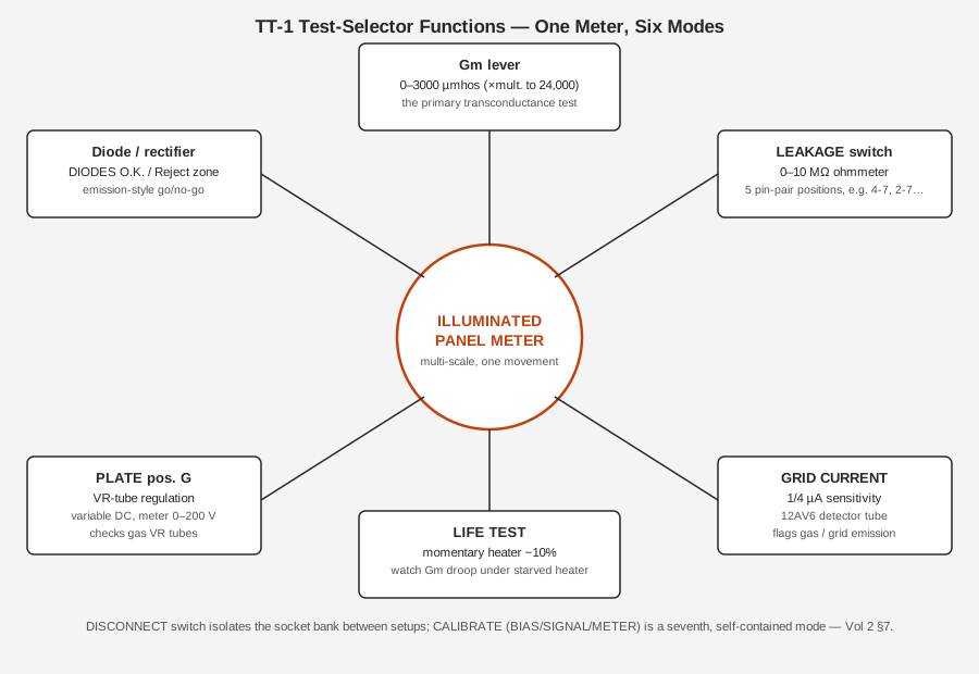
The Gm test is the headline function, but the same chassis carries five more, sharing the same meter, the
same socket bank, and (mostly) the same plate/bias/filament supplies already described. See
figs/vol2_test_functions.svg for how these hang off the one meter movement.
2.7.1 Grid Current / Gas Test
A tube with a soft vacuum (residual gas inside the envelope) or contaminated grid material can develop a small but real DC current flowing in the grid circuit under normal bias — normally the grid draws essentially zero current, so any measurable grid current is diagnostic of a fault. Physically, this current comes from two related mechanisms: residual gas molecules ionized by the electron stream, whose positive ions are attracted to the negatively-biased grid; and, separately, contamination or thermal emission from the grid structure itself acting as a weak secondary cathode. Either way, the symptom is the same — a DC current where there should be none.
The TT-1’s GRID CURRENT function is built around a second dedicated instrument tube, a 12AV6 (a triode-diode-diode originally a common AM-radio detector/audio-preamp type), used here purely as a sensitive current detector rather than in its usual radio role. The quoted sensitivity is ¼ microampere — enough to catch grid current levels well below what would be obviously destructive, flagging marginal gas/emission problems before they become gross failures. This is a complementary check to the leakage test (§7.2): leakage is a resistive short-circuit path between elements that exists whether or not the tube is powered up in its normal mode, while grid current specifically indicates gas ionization or grid emission happening during normal biased operation.
2.7.2 Shorts / Leakage Test
A direct-reading leakage ohmmeter, scaled 0–10 megohms on the same panel meter, checked via the LEAKAGE switch across five selectable pin-pair combinations (the manual’s verification procedure exercises pin pairs such as 4-7, 2-7, 5-7, 6-7, and 1-7 as worked examples). This catches the classic tube short — warped or sagging elements physically touching, or a resistive leakage path from contamination or a cracked support — and it is independent of whether the tube’s cathode still emits or its grid still controls current normally; a tube can pass Gm and grid-current cleanly and still be shorted, or vice versa. Practically, a technician runs the leakage check before the Gm test on an unfamiliar or salvage tube, precisely because a badly shorted tube pushed straight into a biased Gm test can draw damaging current through elements never meant to carry it — the R20 protection note in §3.2 is the concrete failure this discipline avoids.
2.7.3 Life Test
A momentary LIFE TEST switch drops the heater voltage roughly 10% below its normal setting while the operator watches the Gm reading. A genuinely healthy tube’s transconductance holds up reasonably well under a modest heater under-drive; a tube with a cathode nearing end-of-life (reduced emissive coating, cathode poisoning) shows a disproportionate Gm droop when starved even slightly. This is a clever reuse of the existing heater supply and Gm circuit rather than a separate test stage — it’s essentially an accelerated, non-destructive preview of the aging failure mode the emission-test school of tube testers (the Supreme 385) is built around, folded into the Gm instrument as a secondary check rather than the primary one.
2.7.4 Voltage-Regulator (VR) Tube Test
Gas voltage-regulator tubes (the 0A2/0B2/0C3/0D3 family and similar) don’t amplify — they regulate a DC voltage by striking and sustaining a stable gas discharge — so neither the Gm test nor a conventional emission test applies to them. The TT-1 handles this with a dedicated mode: PLATE switch position G selects a variable DC supply, 0–200 V, read on the same panel meter, letting the operator dial voltage up and confirm the VR tube strikes and regulates within its rated range rather than reading a fixed pass/fail number.
2.7.5 Diode / Rectifier Test
For rectifier and other diode-type tubes, the meter carries a marked zone reading “DIODES O.K.” / Reject — an emission-style go/no-go check appropriate to a device that has no grid to test transconductance through in the first place. This is the one function on the TT-1 that is conceptually closer to what the Supreme 385 does across its whole tube range — a reminder that “emission testing” is not obsolete technology so much as the correct tool for element types (diodes, rectifiers) that don’t have a controllable third element to measure gain through.
2.7.6 Other Provisions
The manual and the Heathkit-museum listing also describe support for low-power thyratrons and electron-ray (“magic eye”) indicator tubes, a “hybrid”/auto-radio provision, and a dedicated 26 V space-charge-grid supply position for space-charge tubes (battery/portable-radio types that use a low-voltage auxiliary grid near the cathode rather than conventional plate-voltage-scale operation). These share the existing plate, bias, and socket-selector infrastructure rather than adding separate circuitry, and are set up the same way as any other tube type — per the roll chart’s data for that specific type.
2.8 Line Regulation and the Pin-Routing Switch Matrix
Two more circuit-level ideas make the whole method above actually work reliably on the bench, and both are easy to overlook next to the oscillator and the meter: keeping the incoming line voltage itself steady, and getting each of the four established supplies (§3) routed to the correct pins of whatever oddball tube is sitting in the socket.
2.8.1 SET LINE and LINE CHECK: Why Supply Stability Matters Here
Every filtered DC and AC rail the TT-1 produces — plate, bias, filament, and the oscillator’s own supply — is ultimately derived from the power transformer’s secondary windings, referenced to whatever the AC line happens to be doing at the wall outlet at that moment. Household line voltage was never a tight tolerance even in 1959, and it is worse today with modern loads sagging local branch circuits under load. Because the Gm reading depends on the ratio of a known signal swing to the resulting plate-current swing, and because several of the supporting supplies (especially the plate voltage) scale with line voltage rather than being independently regulated, a sagging or surging line can shift every downstream test point at once.
The SET LINE control is a continuously variable line-voltage adjustment, paired with a LINE CHECK/LINE TEST meter position that shows the operator where the corrected line voltage sits relative to a reference mark on the meter face. The operator’s first move before dialing in any tube is to bring the meter needle to that reference with SET LINE — in effect, a manual line-voltage regulator using the meter itself as the null indicator, rather than a separate regulated supply or a variac. This single step is what lets every voltage table in §3 be trusted as written, rather than as “approximately” correct depending on what else happens to be running on the same branch circuit that day.
2.8.2 The P/G/K Bus: Routing One Measurement Circuit to Any Element
A tube tester built to handle everything from a 4-pin triode to a 9-pin miniature multi-section tube cannot simply hard-wire “pin 3 is always the plate.” Pinouts vary by tube family, and multi-section tubes (dual triodes, triode-pentodes) put more than one complete tube inside a single envelope with its sections sharing some pins and not others. The TT-1 solves this with two layers of switching working together:
- Per-pin selector switches — a bank of rotary switches, one per socket pin, each set per the roll chart to route that physical pin to the correct role (filament, plate, screen, control grid, cathode, suppressor, or unused) for the specific tube type dialed in. This is the layer that adapts the instrument to an arbitrary pinout; Vol 3’s hardware section covers the switch bank itself in physical/mechanical detail.
- P, G, K bus switches — once each pin has been assigned a role by the selector switches, the P/G/K bus switches choose which one of the (possibly several) elements wired to the “plate” role, the “grid” role, and the “cathode” role actually gets connected to the measurement circuit’s plate supply, grid signal, and cathode return for this particular test. On a single-section tube this is a formality — there is only one plate, one grid, one cathode. On a dual triode, it is how the operator tests section 1, then flips the P/G/K switches to the second section’s element set and re-runs the test, all without touching the per-pin selector switches or moving the tube.
This two-layer scheme is the circuit-theory reason multi-section testing takes a second pass rather than a single combined reading (§6.2’s first limitation): the measurement circuit — the oscillator’s grid injection point, the plate-current sense path, the bias return — is a single physical circuit with one set of terminals. The P/G/K bus switches are what let that one circuit be re-pointed at either section of a dual triode in turn, rather than requiring two complete parallel measurement circuits built into the instrument.
2.8.3 DISCONNECT and Setup Safety
A DISCONNECT switch isolates the socket bank from the supplies entirely. Its role is straightforward but important for both tube and operator safety: with a tube seated and DISCONNECT engaged, the operator can set the per-pin selectors and the P/G/K bus to match the roll chart before any plate, bias, or signal voltage reaches the tube’s pins. Only once the setup is verified against the chart does the operator move off DISCONNECT and proceed to leakage, then Gm. This ordering matters because a tube whose pins get momentarily cross-connected mid-setup — plate voltage briefly landing on what should have been a grid pin, for instance — can be damaged or, in a worst case, present a shock hazard at an unexpected pin if the case happens to be open during setup.
2.8.4 Front-Panel Control ↔ Circuit Function, at a Glance
Table 5 — Front-Panel Control ↔ Circuit Function, at a Glance
| Front-panel control | Circuit function |
|---|---|
| SET LINE + LINE CHECK/LINE TEST | Corrects incoming AC line voltage before every supply that derives from it |
| Per-pin selector switches (pins 1–5 top row, 6–9 bottom row) | Route each physical socket pin to its functional role (filament/plate/screen/grid/cathode) per the roll chart |
| P, G, K bus switches | Select which routed element actually connects to the plate/grid/cathode measurement terminals — the multi-section-tube mechanism |
| FILAMENT | Selects rated heater voltage, or a 300/450/600 mA constant-current mode for series-string tubes (§3.1) |
| PLATE (A–G) | Selects plate supply mode: AC test positions, filtered DC 26/90/135/225 V, or variable DC for VR testing (§3.2) |
| BIAS RANGE (L/H) + BIAS pot | Sets the DC grid bias operating point, 0–20 V (§3.3) |
| SIGNAL (2/1/0.5/0.25 V) | Selects the AC grid-drive amplitude from the 3A4 oscillator (§4.1) |
| METER (sensitivity/multiplier) | Scales the meter via multipliers for the expected Gm range of the tube under test, up to the ~24,000 µmhos ceiling |
| Gm lever | Connects the AC plate-current sense path to the meter for a transconductance reading |
| LEAKAGE | Selects one of five pin-pair combinations for the 0–10 MΩ leakage ohmmeter (§7.2) |
| GRID CURRENT | Engages the 12AV6 grid-current detector, ¼ µA sensitivity (§7.1) |
| LIFE TEST (momentary) | Drops heater voltage ~10% to preview cathode-aging droop (§7.3) |
| DISCONNECT | Isolates the socket bank from all supplies during setup (§8.3) |
| CALIBRATE (BIAS/SIGNAL/METER) | Self-calibration sequence against internal precision references (§9) |
2.9 The Self-Calibration Loop
One of the more sophisticated design choices in the TT-1, especially for a solder-it-yourself kit instrument from 1959, is that it needs no external reference tube, no standard, and no separate voltmeter to calibrate itself. A three-position CALIBRATE switch — BIAS / SIGNAL / METER — walks the operator through checking and resetting each of the three quantities the Gm measurement depends on, using internal precision components as the reference rather than an outside standard:
- A precision 0.22 µF, 2% tolerance capacitor, mounted behind the CALIBRATE switch, anchors the signal/meter calibration step. Because it’s a tight-tolerance part in a position that sees relatively gentle electrical stress, refurbishment guidance (Vol 5) treats it as a part that’s usually still within spec decades later and worth verifying in place rather than swapping preemptively.
- Precision resistors (unspecified exact values from the sources reviewed, but described in the manual’s verification procedure as 1%-tolerance parts) anchor the bias and meter legs of the same calibration sequence.
- The BIAS step resets the internal trimmer against the calibration reference; the SIGNAL step verifies the oscillator’s actual output amplitude at each SIGNAL switch position against the calibration cap; the METER step zeroes and spans the meter movement itself.
Because the frequency-setting cap (§4.1) and the meter-coupling cap are allowed to drift within generous tolerances — the manual’s refurbishment guidance treats roughly ±25% as acceptable on both — the self-calibration procedure is explicitly what makes that drift tolerance workable: a 5 kHz oscillator that’s actually running at 7 kHz (as Nickerson measured on his own unit) still produces a trustworthy Gm reading, because the METER and SIGNAL calibration steps are checking the instrument’s actual signal amplitude and meter response at whatever frequency it happens to be running, not assuming the nominal 5 kHz figure printed on the panel. The AC filament cap (§3.1) is a different case entirely, and it is not covered by this same drift-tolerance logic: its aging failure mode is a rising capacitance that pushes the constant-current heater output well above 300/450/600 mA, with no calibration step anywhere in the CALIBRATE loop that touches or compensates the heater supply — which is exactly why §3.1’s danger note singles it out as the single most failure-prone component in the instrument rather than a tolerable drift the way the frequency and meter caps are. This is a meaningfully different design philosophy from an instrument that would need to be sent out for calibration against a lab standard — the TT-1 was built to be field-serviceable and self-checking on the technician’s own bench, which lines up with its whole kit-built, service-shop market positioning. Full calibration procedure, in operator-sequence form, is Vol 5’s territory; this section is the “why it works” companion to that “how to do it.”
2.10 Instrument Tubes: A Two-Tube Instrument, By Design
It is worth stating plainly just how minimal the TT-1’s own active-device count is, because it underscores how much of the design’s cleverness is in passive component values, switch-bank routing, and the self-calibration philosophy (§9) rather than in circuit complexity. Excluding the tube under test itself, the entire instrument runs on exactly two active devices:
Table 6 — the entire instrument runs on exactly two active devices
| Tube | Role | Notes |
|---|---|---|
| 3A4 | ~5 kHz signal oscillator | Battery-portable pentode repurposed purely as a signal source; sets the AC grid-drive signal (§4.1) |
| 12AV6 | Grid-current / gas detector | AM-radio detector/preamp triode-diode-diode type, repurposed as a ¼ µA current detector (§7.1) |
Everything else that makes the Gm measurement work — the plate/bias/filament supply switching, the roll chart’s data encoding, the meter scaling, the leakage ohmmeter, the VR-test variable supply, the self-calibration reference network, the SET LINE regulation loop and the P/G/K routing matrix (§8) — is built from passive components (resistors, capacitors, transformers, switches) and the meter movement itself. This is a deliberate contrast with genuinely tube-heavy vintage test gear of the same era; the TT-1’s sophistication is almost entirely in what its switch matrix and roll chart do, not in how many active stages it carries.
2.11 Putting It Together: The Full Signal Path
figs/vol2_gm_method.svg collects everything in §§3–5 into one picture: the three “setup” supplies
(filament, plate, bias) establish the operating point on the left/right/bottom of the tube-under-test block;
the oscillator and SIGNAL switch inject the small AC test signal onto the grid from the top; the resulting
AC plate-current swing is drawn off the bottom and read out on the meter, scaled to µmhos and checked against
the roll-chart minimum.
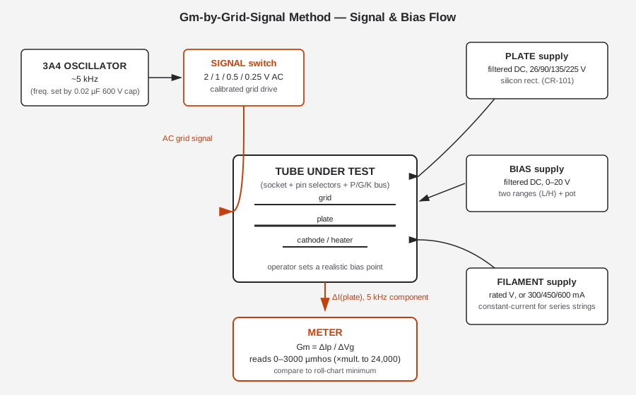
Reading this diagram left to right and top to bottom is, in effect, the entire theory of operation of this instrument: three supplies establish where the tube is operating, one oscillator/switch pair perturbs it by a known small amount, and one meter reports how much the tube’s plate current moved in response — which is, definitionally, transconductance. Vol 3 picks up from here on the hardware side (how the chassis, meter, sockets, and roll-chart mechanism are physically built); Vol 4 walks the same signal path from the operator’s chair, as a setup-and-read procedure rather than a circuit description.
Sources
Primary / manuals / schematics:
- Heathkit TT-1 Operation/Assembly Manual (OCR mirror) — rsp-italy.it: https://www.rsp-italy.it/Electronics/Kits/_contents/Heathkit/Kits/Heathkit%20TT-1%20Tube%20tester%20Manual.pdf
- Internet Archive — Heathkit TT-1 Gm Tube Tester: https://archive.org/details/Heathkit_TT-1_Gm_Tube_Tester
- Internet Archive — Heathkit TT-1A Tube Tester (schematic): https://archive.org/details/Heathkit_TT-1A_Tube_Tester_schematic
- Internet Archive — Heathkit TT-1A (TTA-1-1 socket-adapter assembly manual, 8-29-69): https://archive.org/details/Heathkit_TT-1A_Tube_Tester
- Internet Archive — Heathkit TT-1 Tube Tester data (roll-chart/tube-data archive): https://archive.org/details/Heathkit_TT-1_Tube_Tester_data
- Tube-data supplement (November 1978): https://www.pestingers.net/pdfs/heathkit-test/t1a-supplemental-78.pdf
Hands-on refurbishment (primary, detailed):
- Kent Nickerson, “Refurbishment and Verification of the Heathkit TT-1 Tube Tester” (PDF): https://paulcarbone.com/blog/wp-content/uploads/2020/06/TT1_Refurbishment.pdf (Wayback mirror: https://web.archive.org/web/2id_/https://paulcarbone.com/blog/wp-content/uploads/2020/06/TT1_Refurbishment.pdf)
Museum / reference:
- Heathkit Virtual Museum — TT-1: https://heathkit-museum.com/test/hkTT-1.html
- RadioMuseum — Heath Tube Tester TT-1: https://www.radiomuseum.org/r/heath_tube_tester_tt_1_tt.html
- Alan Douglas, Tube Testers and Classic Electronic Test Gear (ISBN 1886606145) — reviews the TT-1; notes the corrected-Gm arithmetic (§5.3).
- RDF Products application note VR_APL_004 (TT-1A chassis figures): http://www.rdfproducts.com/vr_apl_004.pdf
Weston lineage and the 5 kHz-vs-60 Hz design-fork discussion:
- Weston 981: http://www.vacuumtubes.com/981.html
- Weston 981 Type 3: https://vintagetubeelectronics.com/weston-981-type-3-tube-tester/
- “Weston 981-3 vs. Heathkit TT-1 tube testers” — rec.antiques.radio-phono via narkive: https://rec.antiques.radio-phono.narkive.com/idZqSxCH/weston-981-3-vs-heathkit-tt-1-tube-testers
Corroboration (forum sources — used only to corroborate, per the confidence caveats in §4.2 and §5.3):
- Audiokarma, “Heathkit TT-1 tester thoughts”: https://audiokarma.org/forums/threads/heathkit-tt-1-tester-thoughts.338420/
- Antique Radio Forums TT-1 threads: t=331175, t=387718 (TT-1A), t=361415 (pictures), t=219451, t=192811.
See also: Vol 1 (Overview — What This Tube Tester Is & the Emission-vs-Gm Question), Vol 3 (Inside This Unit — Hardware, Meter, Sockets & Setup), Vol 4 (Using It — Setting Up & Grading a Tube), Vol 5 (Refurbishing & Calibration), Vol 6 (Cheatsheet & Emission vs Gm — the Two-Tester Bench), and the sibling dive at Supreme Instruments 385 Automatic Tester.