Heathkit TT-1 Tube Tester · Volume 3
Heathkit TT-1 — Vol 3: Inside This Unit — Hardware, Meter, Sockets & Setup
One illuminated meter, one built-in roll chart, and a bank of rotary switches stand between a roll of solder and a professional-grade Gm reading.
3.1 Scope of this volume {.unnumbered}
Vol 1 asked what kind of tester this is; Vol 2 worked through the Gm measurement theory. This volume opens the case and walks the hardware, front to back: the single illuminated meter and its five overlaid scales, the roll chart built into the panel itself, the per-pin selector switches and the P/G/K bus that route a tube’s elements to the measuring circuit, the socket complement (and what the TT-1A adds), and the power supply that stands behind all of it — silicon rectifiers, four plate-voltage taps, an adjustable bias supply, and a constant-current filament drive unusual enough to be worth its own section. Setup procedure — actually dialing in and grading a tube — is Vol 4; this volume is the parts list and the “what it’s for,” told from the front panel inward.
It’s worth naming, up front, what kind of hardware complexity this instrument represents relative to the sibling emission tester on the same bench. The Supreme 385 (Vol 6 develops the full comparison) is built around a single “Automatic” rotary knob and a handful of fixed test positions — elegant, fast, essentially foolproof, and mechanically simple enough that most of its failure modes are contact wear and nothing more exotic. The TT-1 trades that simplicity for range and precision: nine independent rotary selectors, a three-switch element bus, a built-in illuminated data chart, a dedicated signal oscillator, and a self-calibration network, all so the meter can read an actual number instead of an arc. Every extra part in this chapter is in service of that number.
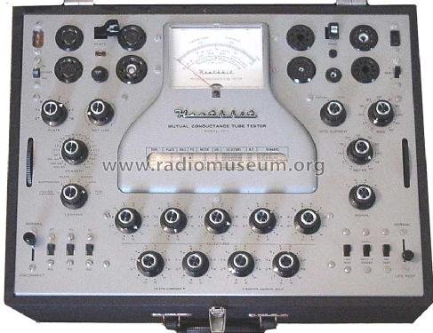
3.2 The front panel at a glance
Heath laid the TT-1’s controls out in the same top-to-bottom logic every operator ends up using: chart at eye level, meter above it for a instant read, selector and bus switches below within thumb’s reach, and the supply/range controls (PLATE, BIAS, SIGNAL, METER, FILAMENT, SET LINE) along the bottom edge. There is no second enclosure and no chart drawer to pull out — everything in this section lives on one panel, in one case.
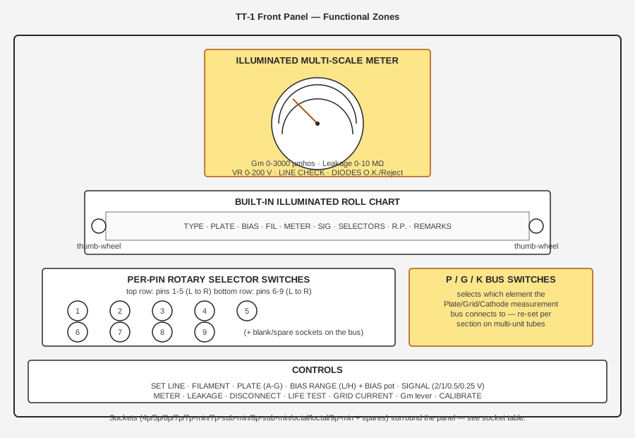
Table 1 — The front panel at a glance
| Zone | What lives there | Detail in |
|---|---|---|
| Meter | Single illuminated multi-scale meter | §2 |
| Roll chart | Built-in, illuminated, thumb-wheel driven | §3 |
| Selector bank | Rotary switches, one per socket pin (1–9) | §4.1 |
| P/G/K bus | Plate / Grid / Cathode routing switches | §4.2 |
| Sockets | 4-pin through 9-pin miniature, octal, loctal, sub-min, spares | §5 |
| Control row | SET LINE, FILAMENT, PLATE, BIAS RANGE + pot, SIGNAL, METER, LEAKAGE, DISCONNECT, LIFE TEST, GRID CURRENT, Gm lever, CALIBRATE | Vol 4 |
⚠ Danger — Every socket on this panel can be carrying tube plate voltage up to 225 VDC and bias voltage down to −20 V the moment the line cord is plugged in and PLATE is set to a live position. Treat the whole socket field as hot until DISCONNECT is thrown and the unit is powered down. See
_shared/legal_ethics.mdfor the mains/HV discipline this hub applies to every tube-era instrument.
3.3 The meter — one face, five jobs
The TT-1 carries a single illuminated panel meter, and Heath got everything it needed to display onto that one face by overlaying five separate scale arcs rather than fitting five separate meters. It is the visual center of the instrument — the roll chart tells the operator what to set, the meter tells the operator what the tube did.
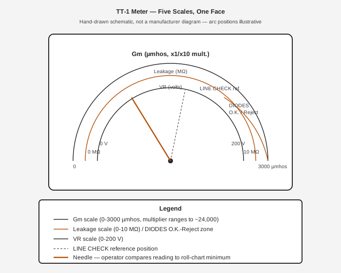
Table 2 — The meter — one face, five jobs
| Scale | Range | Used for | Notes |
|---|---|---|---|
| Gm (transconductance) | 0–3000 µmhos, with multipliers to ~24,000 µmhos | The primary Gm test (Vol 2) | Compare to the roll-chart minimum for the tube under test |
| Leakage | 0–10 MΩ | Shorts/leakage test, element-to-element | Direct-reading ohmmeter scale, LEAKAGE switch selects the pin pair |
| Voltage-regulator | 0–200 V | VR-tube regulation test | PLATE switch position G supplies the variable DC |
| LINE CHECK | Reference arrow/zone | Confirms SET LINE has the line voltage correctly trimmed before any other test is trusted | Not a measurement of the tube — a setup check |
| DIODES O.K./Reject | Pass/fail zone | Diode & rectifier tube test | Emission-style go/no-go read, not a numeric Gm figure |
A period museum listing also documents the meter’s underlying electrical figures — usable as a sensitivity reference, though it comes from a single source and is not cross-checked against the schematic here: the movement behaves as roughly 1000 Ω/V AC (1 V full scale) and 80 mA DC full scale depending on which test mode has it patched in.
The meter and its drive transformers are, per the hands-on refurbishment literature, among the most durable parts of the whole instrument — the electrolytics and the AC filament capacitor fail long before the meter movement does. A sticky or drifted meter on a TT-1 that has otherwise been recapped is far more likely to need cleaning and mechanical re-zeroing than a rebuild (Vol 5 covers the procedure).
The meter is illuminated, matching the roll chart, so both can be read without extra bench lighting — a kit-era nicety that also happens to matter for accurate reading of a scale this crowded.
Stacking five scales onto one dial face instead of building five meters is a deliberate cost/complexity trade that runs through the whole instrument: a second (or third, or fourth) meter movement would have been an expensive, heavy, panel-space-hungry way to solve a problem the switch bank downstream of the meter already solves by routing exactly one signal — Gm current, leakage current, VR voltage, or the DIODES rectified signal — onto the movement at a time. The multi-scale face only works because the rest of the instrument’s switching guarantees the meter never has to disambiguate which quantity it’s reading; the operator disambiguates, by knowing which test they just selected and reading the matching arc. That is worth remembering when a TT-1 meter looks intimidatingly busy at first glance: only one arc is “live” for any given control setting, and the roll chart (§3) is what tells the operator which one.
A meter this multiplexed is also less forgiving of neglect than a single- purpose one. Because the same needle and the same pivot serve every test on the panel, a sticky bearing, a bent needle, or a shifted zero doesn’t just cost one function — it degrades the Gm reading, the leakage reading, and the VR reading simultaneously. That is part of why the refurbishment literature treats meter cleaning and mechanical re-zeroing as a standard, expected step rather than an occasional one (Vol 5).
3.4 The built-in illuminated roll chart
This is the detail that most differs from the scaffold this dive corrects: the TT-1 does not have a separate roll-chart unit that sits apart from the tester. The chart is a constant-tension, free-rolling strip built directly into the main panel, back-lit, with a thumb-wheel drive at each side of the chart window. There is one case, one panel, one chart.
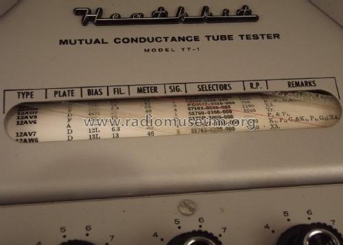
The chart’s columns are effectively the whole setup procedure, printed once per tube type and updated by supplement sheets as new tube types reached the market (Heath issued tube-data supplements for the TT-1 as late as November 1978, well over a decade after the instrument’s introduction — see Vol 1 for the production-span discussion):
Table 3 — for the production-span discussion)
| Chart column | Tells the operator |
|---|---|
| TYPE | The tube type number, alphabetized/numbered for scroll-to lookup |
| PLATE | Which PLATE switch position (A–G) to select |
| BIAS | Bias range (L/H) and pot setting |
| FIL | Filament/heater voltage or constant-current setting |
| METER | Meter range/multiplier to use for the Gm reading |
| SIG | SIGNAL switch position (2 / 1 / 0.5 / 0.25 V AC) |
| SELECTORS | The per-pin selector-switch code (§4.1) |
| R.P. | The reject point — minimum acceptable Gm in µmhos for that tube type |
| REMARKS | Special notes: multi-section handling, known quirks, alternate settings |
Reading the chart correctly and transcribing its settings onto the front panel accurately is the single most error-prone step in the whole test procedure — a wrong PLATE or SELECTORS setting doesn’t just misread the tube, it can put voltage on the wrong element and damage a good one. Vol 4 walks the full chart-to-panel transcription procedure in detail; this volume’s job is only to establish that the chart is physically part of the instrument and what each column means.
⚠ Danger — The roll chart’s illumination runs off the same internal supply as everything else on this panel. A cracked or brittle chart-window lens, common on units this old, is a cosmetic problem — but don’t let “just get the light working” turn into probing around the lamp socket with the unit live.
The mechanism itself is unglamorous but purposeful: a constant-tension, free-rolling strip, driven by a thumb-wheel at each edge of the window rather than a single crank, so the operator can scrub back and forth to bracket a tube type without unspooling the whole chart. “Constant-tension” matters mechanically over the instrument’s life — a chart that goes slack sags in its window, gets creased at the fold where it slack-loops behind the panel, or binds against the thumb-wheel spindle; a chart under correct tension tracks smoothly and stays flat and legible behind the lens. Because the chart, its drive, and its lamp are all fixed to the panel rather than to a separable sub-assembly, there is no “pull the chart drawer to service it” step on this instrument the way the (corrected) scaffold once assumed — chart service on a TT-1 is panel service.
Content-wise, the roll chart is effectively the entire tube-data library the instrument shipped with, updated the same way any printed reference is updated: by supplement. Heath’s practice of issuing periodic tube-data supplement sheets — the latest located for this dive dated November 1978 — meant an owner could keep a TT-1 bought in 1959 current against tube types that didn’t exist yet when the original chart was printed, without buying a new instrument or a new panel. That is also why an original TT-1 chart, on its own, undercounts what the instrument can actually test on a well-maintained unit: the base chart plus whatever supplements survived with it is the real reference.
3.5 Setting up a tube — pin selectors and the P/G/K bus
3.5.1 Per-pin rotary selector switches
Where the Supreme 385 (the emission-tester sibling to this instrument, see Vol 6) uses a single “Automatic” selector knob that pre-wires common tube pin patterns, the TT-1 takes the opposite approach: a bank of individual rotary selector switches, one per socket pin. The bank is laid out in two rows — pins 1–5 left to right on the top row, pins 6–9 left to right on the bottom row — and each switch routes that physical pin to whichever internal bus (filament, plate, screen, control grid, cathode, suppressor, or “not used”) the chart’s SELECTORS code specifies for that tube type.
This is more setup work per tube than a single-knob emission tester, but it’s what makes the TT-1 socket-agnostic: the same nine switches, reconfigured, can wire up a 4-pin acorn tube, a 9-pin miniature, or anything else the socket complement (§5) physically accepts, because the switches — not a fixed per-socket wiring harness — decide what each pin does.
3.5.2 P, G, K bus switches
Once the pin selectors have routed the physical socket pins to the internal element buses, the P (plate) / G (grid) / K (cathode) bus switches decide which of those buses the measuring circuit itself is connected to for this particular test. This is the mechanism that lets the TT-1 test one section of a multi-section tube at a time: for a dual triode, the operator runs the Gm test once with P/G/K addressing triode section 1, then re-sets the bus switches (and often the pin selectors) to address section 2, and runs the test again. Nothing about the socket or the tube changes between the two passes — only which internal element set the meter is actually reading.
Cross-ref: the theory of why the measurement needs a plate/grid/cathode bus at all — the small-signal Gm derivation — is Vol 2 §2; this section is only the mechanical “how do I point the meter at triode #2” answer.
3.5.3 Worked example — a dual triode, two passes
It’s easier to see why the pin-selector-plus-bus architecture exists at all by walking through a tube type that actually needs it: a dual triode (the 12AX7-class family is the archetypal example — two independent triode sections sharing one envelope and one heater, each with its own plate, grid, and cathode pins). The roll chart’s SELECTORS column for such a tube encodes two separate settings, one per section, because the pin-to-element mapping genuinely differs between the two triodes sharing the bottle:
- Pass 1 — section 1. The operator sets the nine pin selectors per the chart’s first SELECTORS code, routing section 1’s plate, grid, cathode, and the shared heater pins to their correct internal buses. The P/G/K bus switches are then set so the measuring circuit is reading that plate, that grid, and that cathode. PLATE, BIAS, and SIGNAL are set from the chart as usual (§ Vol 4), the Gm lever is pressed, and the meter reads section 1’s transconductance.
- Pass 2 — section 2. Without moving the tube, the operator re-sets the pin selectors to the chart’s second SELECTORS code (section 2’s plate/ grid/cathode pins) and re-sets the P/G/K bus to match. Everything else — PLATE, BIAS, SIGNAL, METER range — typically stays the same, because both triodes in a matched-pair dual triode are usually specified to the same operating point and the same reject figure, though the chart is the authority if the two sections differ. The Gm lever is pressed again, and the meter reads section 2 independently.
Nothing about the socket or the tube itself changes between the two passes — the tube sits in the same socket the whole time. What changes is purely switch state: which physical pins the selector bank routes to which internal bus, and which of those buses the P/G/K switches let the meter listen to. This is the mechanical reason a “single Automatic knob” design like the Supreme 385’s cannot do a true independent-section Gm test the way the TT-1 can: a fixed per-tube-type knob position wires all of a tube’s pins to a single predetermined pattern in one motion, which is exactly what an emission test wants (total space current, whole tube, one number) and exactly what a per-section Gm test cannot use.
3.6 The socket complement
The TT-1’s socket field is built to swallow essentially every octal-era and miniature tube type Heath expected a service bench to encounter in 1959–1960, plus blank sockets wired onto the pin bus for oddities the designers didn’t anticipate.
Table 4 — The socket complement
| Socket type | Typical tube families | Notes |
|---|---|---|
| 4-pin | Very early triodes/rectifiers, some acorn types | Legacy coverage |
| 5-pin | Early triodes, some rectifiers | Legacy coverage |
| 6-pin | Older receiving tubes | Legacy coverage |
| 7-pin (large) | Older large-base tubes | Predates the 7-pin miniature |
| 7-pin miniature | Common post-war miniature triodes/pentodes | High-traffic socket on a 1959-era bench |
| 7-pin sub-miniature | Sub-miniature military/hearing-aid-class tubes | Niche but present |
| 8-pin sub-miniature (loctal region) | Sub-miniature types sharing the loctal footprint area | Niche but present |
| Octal | Classic 6L6/6SN7/5U4-class octal-base tubes | High-traffic socket |
| Loctal | Loctal-base tubes (common in some radio/TV chassis) | High-traffic socket |
| 9-pin miniature | Common post-war 9-pin miniature types (12AX7-class) | High-traffic socket |
| Blank/spare sockets | Wired onto the pin bus for future or odd types | Future-proofing, per the manual |
That is a wide net for a 1959–1960 kit, and it is why the TT-1 stayed in Heath’s lineup — and in service benches — well into the 1970s even as newer tube families appeared. But two families that did appear after the TT-1’s original design freeze needed sockets the base unit simply does not have: 12-pin Compactron and Nuvistor.
The blank/spare sockets deserve a second look, because they are the detail that reveals how the designers were thinking about obsolescence. A blank socket, wired onto the same pin bus every named socket uses, has no predetermined tube family — it exists so a technician (or Heath itself, via a later supplement) could adapt the instrument to a socket type nobody had anticipated, without any change to the switching, the bus architecture, or the power supply behind it. That is the same “future-proofing” instinct behind the constant-current filament taps (§6.4) and, at a larger scale, behind the whole TTA-1-1 adapter concept below: rather than treat the socket field as fixed at the factory, Heath built in deliberate slack for whatever came next.
3.6.1 The TT-1A: TTA-1-1 socket adapter — not a revision
This is the second scaffold correction this dive makes, and it is worth stating plainly because “TT-1A” reads, to a modern ear, like a circuit revision the way “465B” or “Mark II” would. It is not.
TT-1A = a TT-1 plus the TTA-1-1 tube-socket adapter. The adapter mounts in the case lid and adds a 12-pin Compactron socket and a Nuvistor socket, wired to tap the existing pin-selector bus. Introduced roughly 1962. The only circuit changes anywhere in the instrument are minor wiring modifications needed to let the adapter reach that bus — there is no performance improvement, no re-engineered supply, no new test mode. Collectors describing a TT-1A as “an almost exact copy of the Weston 981” are describing the same underlying instrument as the plain TT-1, just with two more sockets bolted on.
Table 5 — The TT-1A: TTA-1-1 socket adapter — not a revision
| TT-1 | TT-1A | |
|---|---|---|
| Base sockets (§5 table) | Yes | Yes |
| TTA-1-1 adapter (Compactron + Nuvistor) | No | Yes, in the case lid |
| Gm measurement circuit | Identical | Identical |
| Power supply | Identical | Identical |
| Roll chart | Built into panel | Built into panel |
| Practical difference | — | Two additional tube families testable; otherwise none |
Compactron tubes (12-pin, multi-section, common in later-1960s TV sets) and Nuvistors (small metal-ceramic triodes used in some tuner front ends) both post-date the TT-1’s original 1959–1960 design. Rather than redesign the whole panel, Heath solved the coverage gap the same way any good kit vendor would: an add-on adapter that reuses the existing pin-selector and P/G/K infrastructure instead of duplicating it.
Mechanically, this is exactly the same insight as the blank/spare sockets above, scaled up: instead of leaving unallocated pins on the existing panel bus for a technician to wire ad hoc, Heath shipped a purpose-built adapter that taps that same bus in a defined way. A tube in the Compactron or Nuvistor socket still gets routed through the identical pin-selector-and-bus logic that every other socket on the panel uses — the adapter adds physical socket contacts and the wiring to reach the existing bus, not a parallel measurement path. That is the concrete, hardware-level reason the TT-1A’s Gm circuit, power supply, and calibration are described above as identical to the plain TT-1’s: there was never a second measuring circuit to build, only two more sockets to wire in.
For an owner deciding whether a given plain TT-1 is “worth” upgrading to TT-1A capability after the fact, the practical takeaway is that the adapter is additive rather than corrective — a TT-1 without the TTA-1-1 is not missing a fix, only missing socket coverage for tube families that hadn’t been invented yet when it was built.
3.7 Under the chassis — power supply
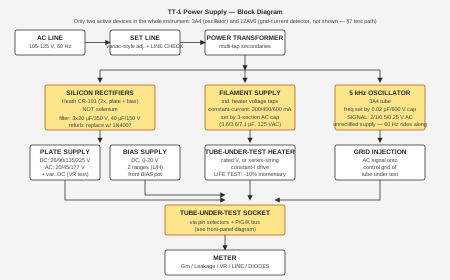
Everything the front panel does — biasing a tube, injecting a signal, reading Gm — is powered from one chassis-mounted supply built around a power transformer with several secondary taps, two silicon rectifier circuits, and a distinctly unusual constant-current filament drive.
3.7.1 Rectification — silicon, not selenium
The third scaffold correction: this instrument’s plate and bias supplies use silicon rectifier diodes, Heath part number CR-101, not a selenium stack. Selenium rectifiers are common enough in tube-era gear of this vintage that assuming one here was a reasonable guess — and wrong. The refurbishment literature is explicit about it: the original CR-101 silicon diodes are “not rugged and commonly fail” with age, and the standard service fix is a direct swap to a modern 1N4007, observing the original’s cathode marking (the red-banded end) for polarity. There is no selenium stack anywhere in the plate or bias path to worry about disposing of on this instrument — a genuinely different service profile than a selenium-rectified sibling.
A single unconfirmed forum aside mentions a small selenium bridge possibly living inside the meter assembly itself, driving the AC-to-DC conversion needed to read the 5 kHz Gm signal on a DC meter movement. That claim has not been checked against the schematic and should be treated as speculative, not as instrument fact, until someone traces it.
Getting this detail right matters for two reasons beyond historical
accuracy. First, safety handling: selenium rectifiers, where they do exist
in tube-era gear, can generate toxic fumes if overheated or arced, and their
disposal is treated differently from an ordinary silicon diode under the
hub’s hazardous-materials guidance in
_shared/legal_ethics.md — a technician
opening a TT-1 expecting to find (and dispose of) a selenium stack in the
main supply is working from the wrong assumption. Second, service
expectations: silicon rectifiers of the CR-101’s era and rating are a known,
common failure point in their own right (below), so “the rectifiers are
silicon, not selenium” is not a reason to expect fewer rectifier problems
on this instrument — only a different failure signature and a different,
simpler fix.
3.7.2 Plate supply
The plate supply is filtered DC, switch-selected across four DC positions and three AC positions, plus a variable DC position reserved for the voltage-regulator test:
Table 6 — voltage-regulator test
| PLATE position | Output | Type |
|---|---|---|
| O | 26 VDC | Filtered DC |
| C | 90 VDC | Filtered DC |
| D | 135 VDC | Filtered DC |
| F | 225 VDC | Filtered DC |
| A | 20 VAC | AC |
| B | 45 VAC | AC |
| E | 177 VAC | AC |
| G | Variable DC, 0–200 V | For the VR-tube test (§ Vol 1/Vol 2 test menu) |
Filtering is handled by a bank of electrolytics — three 20 µF at 350 V plus a 40 µF at 150 V section among others per the parts list — sized to keep ripple off a measurement that is trying to resolve microamp-scale plate current changes at 5 kHz. Recapping this bank with modern 105 °C electrolytics at the original voltage rating (up to roughly double the original capacitance is acceptable practice per the refurb literature) is standard service work — see Vol 5.
The four DC positions are not arbitrary round numbers; they are chosen to bracket the plate operating points a service bench actually encounters across the receiving-tube universe: 26 V covers low-voltage/space-charge and battery-portable designs, 90 V and 135 V cover the bulk of ordinary receiving-tube plate operating points, and 225 V reaches toward larger power tubes and some rectifier/regulator checks. The three AC positions (20/45/177 VAC) exist for tests — rectifier and diode checks among them — where the meter needs to see the tube rectify an AC waveform rather than simply pass a fixed DC current, which is also why the DIODES O.K./Reject zone on the meter face (§2) is a distinct arc from the Gm scale: it’s reading a different kind of signal, off a different plate-supply mode, for a different class of tube.
3.7.3 Bias supply
The bias supply is filtered DC, 0–20 V, with two ranges (L/H) selected at the front panel and a front-panel BIAS pot for fine adjustment, backed by an internal trim adjustment for calibration. Silicon-rectified via the same CR-101/1N4007 family discussed above.
The two-range split (a Low range and a High range both covering some portion of 0–20 V, rather than one pot sweeping the full 20 V) is a resolution choice: a single pot spanning the full range would compress the low end — exactly where most small-signal receiving tubes’ bias points actually fall — into a small, hard-to-repeat arc of pot rotation. Splitting into L/H lets the BIAS pot’s full mechanical travel resolve either the common low-bias tubes or the less common higher-bias types, whichever range the roll chart calls for, without asking one control to do both jobs at once. This is the same kind of range-splitting logic the PLATE switch’s four DC positions apply at a coarser, switched (rather than continuously variable) level.
3.7.4 Filament / heater supply — constant current
This is the power-supply detail most worth dwelling on, because it is genuinely unusual for a tube tester of this era and it is also the single most failure-prone subsystem on the instrument.
Beyond ordinary selectable heater voltages, the TT-1 also offers constant-current filament outputs of 300, 450, and 600 mA — intended for the series-string heater arrangements common in AC/DC receivers and TVs, where tubes are wired heater-to-heater across the line rather than each drawing its rated voltage from a common transformer tap. Heath advertised this as future-proofing against tube families the base voltage taps wouldn’t serve well.
The constant-current behavior is set by a three-section AC capacitor (sections of roughly 3.6 µF, 3.6 µF, and 7.1 µF at 125 VAC) acting as a current-limiting reactance in the heater path — an AC-capacitor current source rather than an active regulator. That makes the cap’s exact value load-bearing: age-related capacitance drift directly changes the current the tube-under-test’s heater actually receives.
The principle is straightforward reactive-impedance current limiting: a capacitor in series with an AC load presents an impedance (reactance) that, at a fixed line frequency, is set almost entirely by its capacitance value — X_C = 1 / (2πfC) — largely independent of what resistance the heater itself presents. Swap in the three switched capacitor sections and the series reactance changes in discrete steps, which is what gives the FILAMENT switch its 300/450/600 mA current-source positions instead of fixed-voltage taps: at 60 Hz line frequency, a larger capacitance means a lower reactance and (for a given supply voltage) a higher available current, which is why the three sections are sized differently rather than identical. This is a passive, reactive analog to a modern active current-limiting supply, built entirely from a switched capacitor bank rather than any regulating circuitry — cheap and rugged when the capacitor is healthy, and exactly why an unhealthy capacitor (one that has drifted upward in value, lowering its reactance and raising the delivered current) is dangerous rather than merely inaccurate: it doesn’t fail open or read wrong, it silently pushes more current into whatever heater is plugged in.
⚠ Danger — This is the AC cap the refurbishment literature singles out as a known failure and fire/heat hazard on this instrument: it can rise in value with age, roughly tripling the delivered filament current, and overheat or bulge under load. Kent Nickerson’s refurbishment report describes simply disconnecting this capacitor on the grounds that few tubes actually need the constant-current drive in practice; if a replacement is fitted instead, it must be an AC-rated film capacitor rated ≥150 VAC — never a DC-rated part pressed into AC service. Full service detail is Vol 5.
The LIFE TEST function piggybacks on this same filament supply: a momentary front-panel switch drops the heater roughly 10% below its set value, and a healthy tube’s Gm reading should hold up under the reduced heater while a weak or marginal one droops visibly — a stress test performed entirely through the filament supply rather than through any separate circuitry.
3.8 The two instrument tubes: 3A4 and 12AV6
For all the switching and metering hardware on this panel, the TT-1’s active circuitry is remarkably small: exactly two tubes do all the work, everything else on the instrument side of the socket field is passive components, the power transformer, and the meter movement.
Table 7 — The two instrument tubes: 3A4 and 12AV6
| Tube | Role | Where it appears in this dive |
|---|---|---|
| 3A4 | 5 kHz grid-signal oscillator — generates the AC test signal injected onto the control grid of the tube under test | Vol 2 §4 (why 5 kHz, not 60 Hz line-derived like a Hickok) |
| 12AV6 | Grid-current detector — senses grid current for the gas/grid-emission test, sensitivity quoted at ¼ microampere | Vol 2 §7 (test-menu discussion; grid-current/gas test at §7.1); grid-current test procedure in Vol 4 |
Both are ordinary, inexpensive receiving-type tubes of the era — Heath did not need anything exotic to build a precision instrument around them, because the precision here comes from the passive network (the calibration components discussed next) rather than from the active devices themselves. That is also why these two tubes rarely turn up as the root cause of a bad TT-1: a weak 3A4 shows up as a drifted signal frequency or amplitude, which the self-calibration procedure (below) is specifically built to absorb.
There is a pointed irony worth naming here, because it is exactly the emission-vs-Gm theme this pair of dives keeps returning to: the 3A4 and the 12AV6 are themselves ordinary tubes that will, eventually, age and weaken by the same mechanisms every tube in this instrument’s socket field can weaken by. Nothing about being “the tester” exempts these two tubes from the physics Vol 2 describes. What protects the TT-1’s accuracy against that aging is not tube quality, it’s architecture — the self-calibration network below measures and compensates for exactly the kind of drift a tired 3A4 or 12AV6 would introduce, so the instrument doesn’t need either tube to be perfect, only healthy enough to oscillate and detect at all. A genuinely dead 3A4 stops the oscillator outright (no Gm test at all, an obvious failure); a merely weakened one drifts frequency and/or amplitude, which CALIBRATE is specifically designed to null out before every test session.
3.8.1 Self-calibration
A CALIBRATE switch with BIAS / SIGNAL / METER positions lets the operator zero out drift in the bias supply, the 5 kHz signal amplitude, and the meter reading — entirely internally, against a precision 0.22 µF, 2% tolerance capacitor and matched precision resistors built into the instrument. No reference tube, no external voltmeter, no outside test gear is required to calibrate the TT-1; it calibrates against its own precision passive components. That 0.22 µF capacitor is specifically called out in the refurbishment literature as a part that is usually still within spec even on units otherwise due for a full recap, and one to verify in place rather than casually replace. Full calibration procedure is Vol 5’s subject; this section only establishes that the capability is built in and needs no external standard.
A related but smaller part, a 0.02 µF, 600 V capacitor, is the frequency- setting component for the 5 kHz oscillator itself. Its measured frequency drifts in practice — Nickerson’s own restored unit measured closer to 7 kHz rather than 5 kHz — but because the CALIBRATE procedure references the signal amplitude the oscillator produces rather than assuming an exact frequency, that drift is absorbed rather than fatal to accuracy. A ±25% tolerance on this cap (and on the associated 0.1 µF meter-circuit capacitor) is considered acceptable for the same reason.
Why a 7 kHz oscillator on a supposedly “5 kHz” instrument doesn’t quietly wreck every reading it’s ever taken is worth spelling out, because it’s the clearest illustration of what self-calibration actually buys: the Gm figure of merit the meter reports is a ratio (ΔI_plate / ΔV_grid, Vol 2 §2), and CALIBRATE’s job is to establish, against the precision 0.22 µF reference and matched precision resistors, exactly how much AC signal amplitude the oscillator is delivering to the grid right now, at whatever frequency it happens to be running. As long as the measuring circuit is calibrated against the oscillator’s actual present output rather than its nominal design output, a drifted frequency changes what is being measured only at the margins (an AC-coupled circuit’s frequency response between 5 kHz and 7 kHz is close enough that the difference falls inside the instrument’s stated accuracy) rather than invalidating the reading outright. This is also why the manual’s tolerance on the frequency-setting cap is a comparatively loose ±25% while the calibration-reference cap itself is a tight 2% — the design puts precision exactly where it is load-bearing (the calibration reference) and tolerates looseness everywhere self-calibration can absorb it (the oscillator’s exact frequency).
3.9 Lineage — a Weston 981-3 inside a Heathkit case
The TT-1’s hardware makes a lot more sense once its ancestry is on the table. It is not an original Heath design worked up from scratch: it is a kit-form redesign of the Weston Model 981, Type 3 (981-3), a professional-grade mutual-conductance tester from 1957. Weston Electrical Instrument Corporation and the Heath Company were both, in the late 1950s, owned by the same parent, Daystrom Inc., which had the 981-3 reworked into solder-it- yourself kit form and restyled cosmetically for the Heathkit line. Collectors describe the later TT-1A in particular as “an almost exact copy of the Weston 981” — reasonable, given that no fundamental redesign separates the TT-1 from the TT-1A in the first place (§5.1 above).
This lineage explains several hardware choices that would otherwise look arbitrary for a consumer kit: the dedicated 5 kHz oscillator rather than a 60 Hz line-derived signal (a design decision inherited whole from a professional instrument, discussed in circuit terms in Vol 2), the direct- reading µmhos meter scale rather than a simplified GOOD/BAD arc, and the depth of the socket/selector/bus architecture, which is more elaborate than most contemporary emission testers bothered with because the Weston design it descends from was built for a bench technician who needed a real number, not a pass/fail light.
No clean period photograph of the parent Weston 981-3 was located for this
dive; the lineage is documented here in prose rather than illustrated. A
<!-- FIGURE SLOT --> is reserved below for Jeff’s own unit rather than for
the Weston, since the Weston itself is not part of this bench pair.
Naming a corporate parent also explains something a photo of either instrument alone would not: why a kit company’s flagship tester carries this much measurement sophistication in the first place. Heath’s other tube-tester line — the TC-1/TC-2/TC-3 emission testers referenced throughout this dive — are Heath-native designs built to a consumer/hobbyist price and complexity point. The TT-1 is not that; it is a professional laboratory instrument’s circuit, simplified only as far as kit assembly and a consumer price point required, wearing a Heathkit badge because its owner at the corporate level happened to own both companies. That is the concrete mechanism behind the “closest kit equivalent to a lab/service-grade Hickok or Weston” framing this dive’s Vol 1 uses — it is not a stylistic resemblance, it is the same design, licensed downward through a shared parent company rather than reverse-engineered by Heath from a competitor’s product.
3.10 Mechanical construction & case
The TT-1 ships (and is normally found today) in a portable wood-frame, fabric- or leatherette-covered carrying case, hinged so the lid opens flush with the panel for bench use and closes over the controls for transport — the same general format as most Heathkit test instruments of the period rather than anything unique to this model. Reported case dimensions vary slightly between sources (roughly 17.75 × 13.5 × 7.5 in per one museum listing, versus roughly 18 × 13.5 × 8.5 in per an auction listing) — treat the two figures as independent measurements of the same class of case rather than a discrepancy worth chasing further. It is AC line powered only, 105–125 V, 60 Hz, with no internal battery — nothing about this instrument’s mechanical architecture is meant to be used away from a wall outlet.
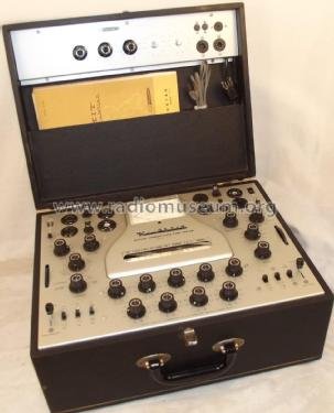
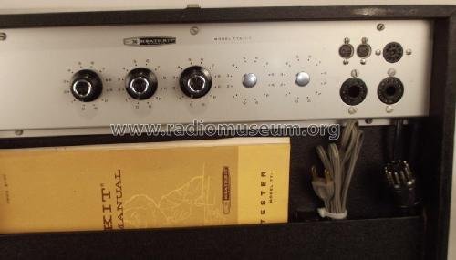
On the TT-1A, the TTA-1-1 socket adapter’s natural home is the case lid itself — mounted where it can be wired back to the panel’s pin bus with a short cable run when the lid is closed against the chassis, and stowed out of the way when the lid is open for normal bench use.
3.11 Known hardware weak points — a preview into Vol 5
This volume has been cataloging what each piece of hardware is for; it’s worth closing the hardware tour with a short preview of what tends to go wrong with it, since several of the components discussed above are called out specifically in the hands-on refurbishment literature as predictable failure points rather than generic “it’s old, everything might fail” hand-waving. Vol 5 covers the actual repair procedures; this table exists so the hardware description above and the service reality connect directly.
Table 8 — Known hardware weak points — a preview into Vol 5
| Component (this volume’s section) | Failure mode | Why it happens |
|---|---|---|
| AC filament capacitor (§6.4) | Value rises with age; can roughly triple delivered heater current; may overheat/bulge | Non-AC-rated or aging film/paper dielectric drifting under continuous AC stress |
| CR-101 silicon rectifiers (§6.1) | Rectifier fails outright | Original small-signal silicon diodes are, per the refurb literature, “not rugged” for this duty |
| Electrolytic filter caps (§6.2) | Ripple increases, output sags, may leak/vent | Ordinary electrolytic end-of-life after 50+ years |
| Paper/wax coupling caps (throughout) | Value drifts, leakage current rises | Wax/paper dielectric degradation, common across the whole tube era |
| R20 (plate-supply resistor) | Burns out | Commonly triggered by a shorting tube under test loading the plate supply |
| Rotary selector switches / slide switches / pots (§4) | Intermittent contact, false readings | Oxidation on contacts that haven’t been exercised in years |
| 7-pin and 9-pin miniature sockets (§5) | False low Gm readings | Worn/spread contacts from decades of insertion cycles |
| Meter movement (§2) | Sticky needle, shifted zero | Mechanical aging; the movement itself rarely needs replacement |
| 0.22 µF 2% calibration cap (§7) | Usually still in spec | Precision part; refurb literature says verify rather than reflexively replace |
The pattern across this table is consistent with the instrument’s overall design philosophy as described throughout this volume: the parts Heath put the least design margin into (a switched AC capacitor doing double duty as a current source, small-signal silicon diodes pressed into a rectifier role) are the parts most likely to fail; the parts that carry the instrument’s actual precision (the meter movement, the 2%-tolerance calibration cap) are built more conservatively and tend to survive.
⚠ Danger — Do not treat this table as a to-do list to work through with the unit powered up. Every component in it sits behind exposed, hot circuitry per the danger callouts throughout this volume; diagnosis and repair belong to Vol 5’s procedures, performed with the unit unplugged and B+ bled down.
3.12 Instrument at a glance — full spec, socket & function table
A single consolidated reference, pulling every figure from this volume’s individual sections into one table.
Table 9 — Instrument at a glance — full spec, socket & function table
| Category | Item | Value / detail |
|---|---|---|
| Identity | Model | Heathkit TT-1 “Mutual Conductance Tube Tester”; TT-1A = TT-1 + TTA-1-1 socket adapter |
| Identity | Maker | Heath Company, Benton Harbor, Michigan (kit form) |
| Identity | Lineage | Redesign of the Weston Model 981, Type 3 (981-3); both owned by Daystrom Inc. |
| Physical | Case | Portable wood-frame carrying case, hinged lid; ~17.75-18 × 13.5 × 7.5-8.5 in (source-dependent) |
| Physical | Power | AC line only, 105-125 V, 60 Hz; no battery operation |
| Meter | Type | Single illuminated multi-scale panel meter |
| Meter | Gm scale | 0-3000 µmhos direct-reading, multipliers to ~24,000 µmhos |
| Meter | Leakage scale | 0-10 MΩ, direct-reading ohmmeter |
| Meter | VR scale | 0-200 V |
| Meter | Other zones | LINE CHECK reference; DIODES O.K./Reject |
| Meter | Reported electrical rating | ~1000 Ω/V AC (1 V full scale); ~80 mA DC full scale (single-source figure) |
| Roll chart | Construction | Illuminated, constant-tension, free-rolling, built into the main panel (not a separate drawer) |
| Roll chart | Drive | Thumb-wheel at each side of the chart window |
| Roll chart | Columns | TYPE, PLATE, BIAS, FIL, METER, SIG, SELECTORS, R.P., REMARKS |
| Roll chart | Data currency | Base chart + periodic tube-data supplements (latest located: Nov 1978) |
| Setup switching | Pin selectors | Rotary, one per socket pin; top row pins 1-5, bottom row pins 6-9 |
| Setup switching | Element bus | P (plate) / G (grid) / K (cathode) bus switches, re-set per section on multi-section tubes |
| Sockets — built-in | Count/types | 4-pin, 5-pin, 6-pin, 7-pin (large), 7-pin miniature, 7-pin sub-miniature, 8-pin sub-miniature, octal, loctal, 9-pin miniature, + blank/spare |
| Sockets — TT-1A adapter | TTA-1-1 adds | 12-pin Compactron, Nuvistor (adapter mounts in case lid, ~1962) |
| Power supply | Rectifiers | Silicon, Heath CR-101 (plate + bias); NOT selenium |
| Power supply | Plate DC | 26 / 90 / 135 / 225 VDC (positions O/C/D/F) |
| Power supply | Plate AC | 20 / 45 / 177 VAC (positions A/B/E) |
| Power supply | Plate variable | Variable DC (position G), for VR-tube test, read 0-200 V |
| Power supply | Plate filtering | 3× 20 µF/350 V + 40 µF/150 V (representative; full parts list in the manual) |
| Power supply | Bias | Filtered DC, 0-20 V, two ranges (L/H), front BIAS pot + internal trim |
| Power supply | Filament — standard | Selectable heater voltage taps per tube type |
| Power supply | Filament — constant current | 300 / 450 / 600 mA, set by a 3-section AC cap (~3.6/3.6/7.1 µF, 125 VAC) |
| Power supply | LIFE TEST | Momentary ~10% heater reduction |
| Instrument tubes | Oscillator | 3A4 — 5 kHz grid-signal oscillator (frequency set by 0.02 µF/600 V cap) |
| Instrument tubes | Detector | 12AV6 — grid-current detector, ¼ µA sensitivity |
| Calibration | Method | Self-contained CALIBRATE switch (BIAS/SIGNAL/METER); no reference tube or external gear needed |
| Calibration | Reference components | 0.22 µF, 2% precision cap + matched precision resistors |
| Test functions | Primary | Dynamic mutual-conductance (Gm), direct µmhos reading vs. roll-chart minimum |
| Test functions | Secondary | Shorts/leakage (0-10 MΩ), grid-current/gas (¼ µA), life test (heater -10%), VR-tube test (0-200 V), diode O.K./Reject |
| Test functions | Also handles | Low-power thyratrons, electron-ray (“magic eye”) tubes, hybrid/auto-radio provision, space-charge supply (26 V) |
| Fuse | Rating | 2 A — confirm fitted before first power-up after long storage |
3.13 Cross-references
- Vol 1 covers the emission-vs-Gm framing and this instrument’s place in the Heath lineup (TC-series emission testers vs. this dynamic Gm design).
- Vol 2 works through the Gm measurement theory this hardware implements — why a 5 kHz dedicated oscillator, the small-signal Gm derivation, and the method’s stated limits.
- Vol 4 is the operator’s-eye walk through actually reading the roll chart, setting the pin selectors and P/G/K bus, and grading a tube start to finish.
- Vol 5 covers refurbishing this hardware in detail: the AC filament capacitor hazard, the CR-101-to-1N4007 rectifier swap, electrolytic replacement, and the self-calibration procedure.
- Vol 6’s two-tester bench cheatsheet sets this hardware directly against the Supreme 385’s emission-test hardware for the side-by-side comparison this pair of dives is built around.
Sources
Primary / manuals / schematics:
- Heathkit TT-1 Operation/Assembly manual (OCR), rsp-italy.it mirror: https://www.rsp-italy.it/Electronics/Kits/_contents/Heathkit/Kits/Heathkit%20TT-1%20Tube%20tester%20Manual.pdf
- Internet Archive — Heathkit TT-1 Gm Tube Tester: https://archive.org/details/Heathkit_TT-1_Gm_Tube_Tester
- Internet Archive — Heathkit TT-1A schematic: https://archive.org/details/Heathkit_TT-1A_Tube_Tester_schematic
- Internet Archive — Heathkit TT-1A (TTA-1-1 socket-adapter assembly manual, model TT-1A, 8-29-69): https://archive.org/details/Heathkit_TT-1A_Tube_Tester
- Internet Archive — Heathkit TT-1 Tube Tester data: https://archive.org/details/Heathkit_TT-1_Tube_Tester_data
- Tube-data supplement (Nov 1978): https://www.pestingers.net/pdfs/heathkit-test/t1a-supplemental-78.pdf
Hands-on refurbishment (primary, detailed):
- Kent Nickerson, “Refurbishment and Verification of the Heathkit TT-1 Tube Tester” (PDF): https://paulcarbone.com/blog/wp-content/uploads/2020/06/TT1_Refurbishment.pdf
Museum / reference:
- Heathkit Virtual Museum — TT-1: https://heathkit-museum.com/test/hkTT-1.html
- RadioMuseum — Heath Tube Tester TT-1: https://www.radiomuseum.org/r/heath_tube_tester_tt_1_tt.html
- Alan Douglas, Tube Testers and Classic Electronic Test Gear (ISBN 1886606145).
- RDF Products app note (VR_APL_004), TT-1A chassis figures: http://www.rdfproducts.com/vr_apl_004.pdf
Weston lineage:
- Weston 981: http://www.vacuumtubes.com/981.html
- Weston 981 Type 3: https://vintagetubeelectronics.com/weston-981-type-3-tube-tester/