Heathkit TT-1 Tube Tester · Volume 4
Heathkit TT-1 — Vol 4: Using It — Setting Up & Grading a Tube
A working tube-tester's operator manual, rewritten as a bench logbook: roll chart to reject figure, one lever at a time.
4.1 Scope of This Volume
This volume is the operator’s manual — what to do, in what order, with a working TT-1 in front of you and a tube you don’t yet trust. Vol 2 covers why the circuit reads Gm the way it does; Vol 3 covers the chassis and switch bank as hardware; Vol 5 covers what to do when a setting won’t hold or a reading looks physically implausible. This volume assumes the instrument is in good working order and walks through a complete test session: reading the roll chart, setting up a tube, running the leakage check, pulling a Gm reading, running the auxiliary tests, and — the part every operator eventually needs — deciding what a marginal number actually means on the bench.
⚠ Danger — The TT-1 is a mains-powered instrument with internal DC as high as 225 V and AC test points that can present a comparable shock hazard. Several of the front-panel controls (SET LINE, PLATE, BIAS) are directly in that circuit. Treat every socket and every exposed lug on the chassis as live whenever the line cord is plugged in — see §11 before you do anything else with an unfamiliar or long-stored unit.
4.2 Before You Touch a Dial
4.2.1 What “using” a TT-1 actually means
The TT-1 does not grade a tube against a single GOOD/BAD arc the way a cheap emission checker does. It is a small bench instrument you configure, tube by tube, against a chart — the roll chart supplies every operating condition (heater, plate voltage, bias, AC signal level, meter range) and the reject figure to compare against. Get the setup wrong — wrong plate voltage, wrong pin selector, wrong P/G/K bus position — and the number on the meter is meaningless or, worse, damaging to the tube. The discipline described below exists because this instrument rewards a fixed sequence and punishes skipped steps.
4.2.2 Fuse and first power-up
Before applying power to a TT-1 that has been sitting — in a case, in an attic, in an estate lot — confirm the 2 A fuse is fitted and intact. This is not a formality: a shorted or gassy tube under test, or a fault inside the instrument itself, is exactly the failure mode the fuse exists to catch, and Vol 5 documents at least one recurring internal casualty (a resistor, R20, that has a history of burning out when a shorting tube is put under test). Running the instrument without its fuse in place — or with a higher-rated substitute — turns a nuisance blown fuse into a damaged instrument.
⚠ Danger — Do not defeat, bridge, or substitute the fuse with anything above its rated 2 A value “just to see if it clears.” The fuse is protecting wiring and the operator, not just the instrument.
4.2.3 What you need on the bench
- The tube under test, handled by the base/envelope — let it reach room temperature if it has been in a cold car or garage; don’t test a tube straight out of a freezing trunk.
- The TT-1 itself, warmed up (a couple of minutes idle is enough — there’s no tube-heater wait built into the instrument itself beyond the socket under test).
- The roll chart is built into the panel — nothing separate to dig out. If your chart data doesn’t cover a tube type (later types, or types added after your unit’s chart was last updated), Heath issued periodic tube-data supplement sheets (see Sources) that extend coverage; keep the relevant supplement pages near the bench.
- A known-good tube of the same or a well-understood type is not required — the TT-1 is self-calibrating (§9) and does not need a reference tube to trust its own reading, unlike some rival instruments of the era.
4.2.4 Front-panel control quick reference
Before working through the step-by-step sections below, it helps to have every control in one place — what it’s called, which roll-chart column drives it (if any), and what it does. Keep this table open on a first pass through the instrument; after a few tubes the sequence becomes automatic.
Table 1 — 1.4 Front-panel control quick reference
| Control | Chart column it follows | Function |
|---|---|---|
| Roll-chart thumb-wheels | — | Scroll the illuminated chart to the tube TYPE. |
| Pin SELECTOR switches (top row 1–5, bottom row 6–9) | SELECTORS | Route each socket pin to the correct internal bus for this tube’s basing. |
| P / G / K bus switches | SELECTORS / REMARKS | Choose which routed element the measuring circuit reads as plate / grid / cathode — set per section on multi-section tubes. |
| FILAMENT | FIL. | Heater voltage, or constant-current (300/450/600 mA) for series-string types. |
| PLATE (A–G) | PLATE | Plate supply mode/level: AC positions, filtered DC positions, or variable DC (VR test). |
| BIAS RANGE (L/H) + BIAS pot | BIAS | Negative grid bias operating point, 0–20 VDC. |
| SIGNAL | SIG. | AC test-signal amplitude on the grid: 2 / 1 / 0.5 / 0.25 V. |
| METER (range/multiplier) | METER | Meter sensitivity/multiplier so the Gm reading lands on scale. |
| SET LINE | — | Continuously variable line-voltage trim; zeroed against LINE CHECK before testing. |
| LEAKAGE | — | Steps through pin-pair positions for the 0–10 MΩ shorts/leakage check. |
| DISCONNECT | — | Removes socket power while re-setting switches, without cycling the whole instrument. |
| Gm test lever | R.P. (for comparison) | Momentary — connects the tube into the live Gm measuring circuit. |
| GRID CURRENT | — | Switches the meter to the ¼ µA-sensitive grid-current/gas check. |
| LIFE TEST | — | Momentary — drops heater ~10% to stress-test a marginal cathode. |
| CALIBRATE (BIAS/SIGNAL/METER) | — | Self-calibration routine; no reference tube or external gear needed. |
4.3 Reading the Roll Chart
4.3.1 Layout
The chart sits under a long horizontal window in the panel, immediately above the meter and selector bank, and is driven by a thumb-wheel at each side of the window — spin either wheel and the whole printed roll scrolls left/right until the tube type you want sits behind the window. It is back-lit, so the print stays legible even under a dim bench lamp. There is no separate drawer or accessory chart case to find — this is the chart, permanently part of the instrument (see Vol 3 §3 for the mechanism itself).
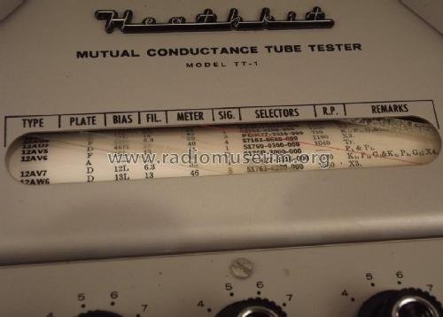
4.3.2 Column-by-column
Table 2 — 2.2 Column-by-column
| Column | What it tells you |
|---|---|
| TYPE | The tube type designation (e.g. an octal or 9-pin miniature number) — scroll to this. |
| PLATE | Which PLATE switch position (A–G) to select — sets plate supply voltage/mode. |
| BIAS | The BIAS RANGE (L/H) and BIAS pot setting — sets the negative grid bias point. |
| FIL. | Which FILAMENT position — heater voltage, or one of the constant-current settings for series-string heaters. |
| METER | Which METER (sensitivity/multiplier) range to select, matched to the expected Gm magnitude. |
| SIG. | Which SIGNAL level (2 / 1 / 0.5 / 0.25 V AC) to inject on the grid. |
| SELECTORS | The per-pin selector code — which internal bus (filament, plate, screen, grid, cathode) each socket pin routes to for this tube type. |
| R.P. | The reject point — the minimum acceptable Gm reading, in µmhos, for this tube type. This is the number step 7 (§7.4) compares the meter against. |
| REMARKS | Notes: multi-section handling, special socket, known quirks for that type. |
Every one of these columns must be read and set before the tube goes under test power. A tube dialed up with the wrong PLATE or BIAS column figure is not being tested to its rated point — worse, an aggressive mismatch (excess plate voltage on a low-power type, for instance) can damage a tube that would otherwise have passed.
4.3.3 If the tube isn’t on your chart
Heath issued periodic tube-data supplement sheets for years after the base TT-1 chart was printed — the latest documented supplement is dated November 1978, meaning a TT-1 or TT-1A could plausibly stay in useful service, correctly configured for newer tube types, well over a decade after purchase. If a type doesn’t appear on the roll chart itself, check for a supplement sheet before assuming the instrument simply can’t handle it — the socket and switch-bank hardware (§3) is general enough that most conventional receiving tubes fit, the limiting factor is usually just whether the setup data has been located, not whether the instrument is physically capable. The Sources list at the end of this volume includes the archived supplement.
4.3.4 The meter face at a glance
The single illuminated meter carries several distinct scales, each relevant to a different test function described later in this volume. Knowing which scale you’re reading — before you press a lever — avoids misreading a Gm arc as a leakage arc or vice versa:
Table 3 — you press a lever — avoids misreading a Gm arc as a leakage arc or vice versa
| Scale | Range | Used for |
|---|---|---|
| Gm (µmhos) | 0–3000, × METER multiplier | The primary transconductance test (§7) |
| Leakage | 0–10 MΩ | Shorts/leakage check (§6) |
| VR | 0–200 V | Voltage-regulator tube test (§8.3) |
| LINE CHECK | Single index mark | SET LINE reference (§5) |
| DIODES O.K./Reject | Marked zone, not a numeric scale | Diode/rectifier test (§8.4) |
The GRID CURRENT and LIFE TEST functions (§8.1, §8.2) read against the Gm/leakage scales already on the face rather than needing dedicated scales of their own — GRID CURRENT is read as a small deflection at the sensitive end of the movement, and LIFE TEST is read as a Gm figure taken under the heater-reduced condition, not a separate number.
4.3.5 Multi-section tubes
A dual triode, triode-pentode, or similar combination type gets one chart row but is tested one section at a time — the REMARKS column will flag which P/G/K bus and selector changes correspond to “section 1” vs. “section 2.” You re-run §3–§7 for each section in turn; nothing about the chart or plate/bias/signal settings usually changes between sections of the same envelope, but the P/G/K bus assignment and possibly a selector or two will.
4.4 Setting Up the Tube — Selectors and the P/G/K Bus
4.4.1 The per-pin selector bank
Unlike the Supreme 385’s single “Automatic” selector knob (a mechanically simpler, single-control approach built for speed on an emission-only tester — see Vol 6 for the side-by-side), the TT-1 uses a bank of individual rotary selector switches, one per socket pin: the top row of switches corresponds to pins 1–5 (left to right), the bottom row to pins 6–9. Each switch is dialed to the code letter/number the roll chart’s SELECTORS column specifies for that pin, on that tube type. This is more setup work per tube than a single-knob automatic tester, but it is what lets one instrument’s socket wiring cover an enormous span of basing conventions — everything from 4-pin globe tubes up through 9-pin miniatures — without a different testing philosophy for each family.
Practical sequence:
- Identify the correct socket for the tube’s base (octal, loctal, 7-pin, 9-pin miniature, etc. — see Vol 3 §4 for the full socket list, and the TTA-1-1 adapter note below).
- Insert the tube fully and squarely; a partially seated tube reads short/open faults that aren’t real.
- Set each per-pin selector switch to the code shown in the chart’s SELECTORS column, pin by pin — don’t skip any, including pins the tube type doesn’t use (those typically go to a defined “blank”/off code, not left at whatever position the last tube left them in).
⚠ Danger — Never insert or remove a tube with the line switched on and a test lever pressed. Sockets carry live plate/bias/heater voltage the instant the corresponding switch positions are set, whether or not a tube is present.
4.4.2 Socket coverage and the TTA-1-1 adapter
The base TT-1 panel carries built-in sockets for 4-pin, 5-pin, 6-pin, 7-pin (large), 7-pin miniature, 7-pin sub-miniature, 8-pin sub-miniature (loctal-region), octal, loctal, and 9-pin miniature tubes, plus a few blank/spare sockets wired onto the pin bus for odd or future types. A unit marked TT-1A is the same tester with the TTA-1-1 socket adapter fitted — a small unit adding 12-pin Compactron and Nuvistor sockets, typically mounted in the case lid. This is purely a socket-coverage addition — the TTA-1-1 adapter was introduced ~1962, after the base TT-1’s original design; there is no meaningful circuit or performance difference between a TT-1 and a TT-1A once the adapter’s socket is selected — don’t expect a different reading philosophy or extra accuracy from the “A” suffix (see Vol 1 §1 for the full correction of this point).
4.4.3 The P, G, K bus switches
Separately from the per-pin selectors, the P (plate) / G (grid) / K (cathode) bus switches choose which internal element the measuring circuit is actually connected to. This is what lets the same physical pin wiring test, say, the first triode of a 12AU7 and then the second: the pin selectors route the socket pins to the right supply/signal buses, and the P/G/K switches tell the meter and oscillator which of those routed elements is “the plate,” “the grid,” and “the cathode” for this measurement. Set P/G/K per the chart’s REMARKS/SELECTORS guidance for the section under test — and reset them (§2.5) when moving to the next section of a multi-section tube.
4.5 Setting the Test Conditions — FILAMENT, PLATE, BIAS, SIGNAL, METER
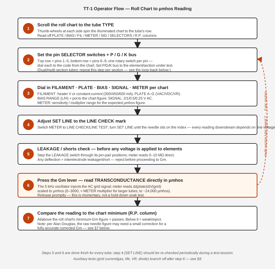
With the tube seated and the selector/bus switches set, dial in the five conditions the chart specifies. Order doesn’t have strict electrical significance here (nothing is powered yet if DISCONNECT is engaged — see §4.6), but working left-to-right across the panel keeps you from skipping one.
4.5.1 FILAMENT
Sets the heater supply to the tube’s rated voltage. Beyond the ordinary AC heater voltage positions, FILAMENT also includes constant-current outputs of 300, 450, and 600 mA — these exist for tubes designed for series-string heater operation (common in AC/DC radio and early TV chassis, where heaters were wired in series across the line rather than in parallel off a transformer tap). The chart’s FIL. column tells you which mode a given type needs; a constant-current type dialed to a voltage position (or vice versa) will not heat correctly and can also produce a bogus Gm reading.
4.5.2 PLATE
Selects the plate supply mode and level:
Table 4 — Selects the plate supply mode and level
| Position | Output | Use |
|---|---|---|
| A, B, E | 20 / 45 / 177 VAC | AC plate positions for certain tube families/tests |
| O, C, D, F | 26 / 90 / 135 / 225 VDC | Filtered DC plate positions — the bulk of normal Gm testing |
| G | Variable DC, 0–200 V (metered) | VR-tube regulation test (§8.3) — not a fixed chart-driven position |
Set to the letter the chart’s PLATE column specifies for the type under test. The DC positions are filtered through the plate supply’s electrolytic bank (Vol 3 §5; Vol 5 covers recapping that bank) — the tube sees clean DC at one of four fixed levels, not raw rectified ripple.
4.5.3 BIAS
BIAS RANGE is a two-position switch (L/H — low/high range) plus a continuously variable BIAS pot, together covering 0–20 VDC of negative grid bias. Set the range switch per the chart, then bring the pot to the chart’s BIAS figure. This establishes the DC operating point the small AC test signal (§4.4) will be superimposed on — get bias wrong and you are reading Gm at the wrong point on the tube’s transfer curve, not at its rated point.
4.5.4 SIGNAL
Selects the amplitude of the 5 kHz AC test signal the internal oscillator (built around a 3A4 tube — see Vol 2 §2) injects onto the control grid: 2, 1, 0.5, or 0.25 V AC. This is the “small AC grid signal” referenced throughout this dive — small enough to stay in the locally linear part of the tube’s transfer curve so the resulting AC plate-current swing is a faithful measure of Gm = ΔI(plate)/ΔV(grid), not a distorted large-signal excursion. Chart figure, not operator judgment, sets this.
4.5.5 METER
Selects meter sensitivity/range multiplier so the expected Gm reading lands on a readable part of the 0–3000 µmhos scale rather than pinned or buried near zero. Small-signal tubes read directly; higher-Gm types (power tubes, some sweep types) need one of the METER multiplier positions to bring readings as high as the instrument’s rated ~24,000 µmhos ceiling onto scale. The chart’s METER column specifies which.
4.5.6 DISCONNECT
A DISCONNECT switch is provided to remove socket power while you’re mid-setup — useful when re-dialing selectors between sections of a multi-section tube, or when pausing to re-check a chart figure, without repeatedly seating/unseating the tube or cycling the whole instrument off. Get in the habit of engaging DISCONNECT while changing pin-selector or P/G/K settings on a tube that’s already seated.
4.6 SET LINE — Checking the Line Voltage First
Every voltage and current figure the chart specifies assumes the instrument’s internal supplies are running from a correctly regulated line reference — and 1959-era 105–125 VAC household mains were not tightly regulated. The TT-1 compensates with a front-panel SET LINE control (a continuously variable line-voltage adjustment) and a LINE CHECK/LINE TEST meter position.
Procedure:
- Switch METER to its LINE CHECK (or LINE TEST) position.
- Turn SET LINE until the meter needle sits exactly on the index mark provided for that check.
- Only then proceed to the leakage check and Gm test below.
This is not a one-time setup step for the session — mains voltage on an ordinary household circuit can sag or rise meaningfully over the course of an evening (a furnace blower or a neighbor’s dryer kicking in is enough), so re-check SET LINE periodically, and always re-check it if a reading looks implausibly off from an earlier session on the same tube type.
4.7 Step 1 of Testing: Leakage / Shorts Check
Do this before running the Gm test — a leaky or shorted tube under full plate/bias voltage can draw damaging current, and a short between elements will simply corrupt whatever Gm figure comes out anyway.
The TT-1’s LEAKAGE function is a direct-reading leakage ohmmeter, 0–10 MΩ full scale, checked pin-pair by pin-pair via the LEAKAGE switch. The switch steps through a set of element-to-element pin pairs relevant to the socket in use — for example, on a socket where pins 4 and 7 are heater/cathode-adjacent pins, positions like 4-7, 2-7, 5-7, 6-7, 1-7 check for leakage or an outright short between those elements and a reference pin (verified in the manual’s calibration procedure using a 100 kΩ–500 kΩ resistor bridged across socket pins to confirm the ohmmeter tracks correctly).
Procedure:
- With the tube seated and pin selectors set (§3), switch to LEAKAGE.
- Step through each pin-pair position the socket/tube type calls for.
- Any needle deflection off the zero end of the 0–10 MΩ scale indicates leakage; a low-Ω deflection (well up-scale toward zero ohms) indicates an outright short.
⚠ Danger — A tube that shows a hard short on the leakage check should be set aside, not pushed on to the Gm test “to see how bad it is.” A shorted element under plate/bias voltage is exactly the fault pattern behind the R20 burnout documented in Vol 5 — don’t repeat it.
4.7.1 Common setup mistakes and their symptoms
A surprising fraction of “bad tube” verdicts on any switch-heavy tube tester are actually setup errors. Before condemning a tube on a strange leakage or Gm reading, check this list:
Table 5 — setup errors. Before condemning a tube on a strange leakage or Gm reading, check this list
| Symptom | Likely cause |
|---|---|
| Leakage check shows deflection on every pin pair, even a known-good tube | Tube not fully seated in the socket, or a wrong socket selected for the base type |
| Gm reads near zero on a tube you have reason to trust | A pin selector left at the previous tube’s code, or DISCONNECT left engaged |
| Gm reads wildly high / pinned | Wrong METER multiplier position, or PLATE set to a higher-voltage position than the chart specifies |
| Reading drifts between otherwise identical repeat tests | SET LINE not re-checked between tests, or line voltage genuinely sagging/rising mid-session |
| Tube runs visibly hot, plate glows red almost immediately | PLATE and/or BIAS set to the wrong chart figures — de-energize immediately and re-verify the chart row |
| P/G/K bus assignment “looks right” but reading is nonsensical | Wrong section selected on a multi-section tube — re-check the REMARKS column for which section the current P/G/K setting corresponds to |
4.8 Step 2: The Gm Test — Reading Micromhos
4.8.1 What the lever does
With FILAMENT/PLATE/BIAS/SIGNAL/METER all set per chart, SET LINE checked, and the leakage check clean, press the Gm test lever. This closes the tube into the live measuring circuit: the 5 kHz oscillator’s small AC signal (§4.4) rides onto the grid, the tube’s plate current develops a corresponding AC component, and the metering circuit rectifies and scales that AC plate-current swing so the needle reads transconductance directly, in micromhos — 0–3000 µmhos on the base scale, extended by the METER multiplier positions to a rated capability of roughly 24,000 µmhos for high-Gm types. See Vol 2 §2–§3 for the full derivation of why an AC-signal method reads gain directly where a DC emission test cannot.
The lever is a momentary control — press, read, release. This is a spot measurement of Gm at the chart’s specified operating point, not a soak or burn-in test.
4.8.2 Reading the scale
Read the needle position against the 0–3000 µmhos arc, then apply whatever METER multiplier position was selected in §4.5 (e.g., a needle reading of 1500 on a ×2 multiplier position is 3000 µmhos actual). Note the figure.
4.8.3 The Alan Douglas correction caveat
Alan Douglas, reviewing the TT-1 in Tube Testers and Classic Electronic Test Gear, notes that the raw needle figure on Weston-lineage instruments of this design may need a small arithmetic correction to arrive at a fully accurate corrected Gm figure — this is a design nuance of the metering/scaling approach, not a fault. This dive has not been able to locate the exact correction formula/table Douglas references (treat this as a caveat to be aware of, not a documented correction routine); if you have Douglas’s book on hand, apply his published correction before treating a borderline reading as definitive. For most bench triage — is this tube clearly good, clearly weak, or worth a second look — the raw reading against the chart minimum is sufficient; the correction becomes relevant chiefly when a reading sits very close to the reject line and the decision matters (a tube going back into an expensive or hard-to-source chassis, for instance).
4.8.4 Comparing to the chart minimum
The roll chart’s R.P. (reject point) column is the pass/fail line: a Gm reading at or above the chart’s R.P. figure for that type is a pass; a reading below it is a reject, regardless of how the tube looks or how it tested on a simpler instrument. This comparison — not a GOOD/BAD arc — is the actual grading step on this instrument. Record both the raw reading and the chart minimum in your bench log; a tube sitting just above reject today is worth flagging for a re-check down the road, not filed and forgotten.
Table 6 — 7.4 Comparing to the chart minimum
| Reading vs. chart minimum | Interpretation |
|---|---|
| Comfortably above R.P. | Tube is healthy at this operating point — pass. |
| At or just above R.P. | Marginal; useable but weak — flag for re-test or replace at next opportunity, especially in a critical stage. |
| Below R.P. | Reject — insufficient gain for reliable service, regardless of emission or leakage results. |
| Near zero / no deflection | Open element, dead cathode, wrong setup, or a genuinely dead tube — recheck setup (§2–§4) before condemning the tube. |
| Pinned / off-scale high | Wrong METER range selected, or a genuine short/runaway condition — recheck METER position and re-run the leakage check. |
4.8.5 A worked example (illustrative only)
The following walks the full sequence against a hypothetical octal beam-power tube, to show how the columns and controls actually chain together in a real bench session. The specific figures below are illustrative, not certified data for any real tube type — always read your own unit’s roll chart (or the applicable tube-data supplement) for the actual figures; do not use this table as service data.
Table 7 — 7.5 A worked example (illustrative only)
| Step | Chart says | Operator does |
|---|---|---|
| Roll chart | TYPE row located | Thumb-wheel to the type; note PLATE=D, BIAS=12L (low range, pot at “12”), FIL.=6.3, METER=×1, SIG.=1, SELECTORS=code for this base, R.P.=2200 µmhos |
| Pin selectors | SELECTORS column code | Dial each per-pin switch (heater to two pins, cathode, control grid, screen grid, plate, per the code) |
| P/G/K bus | REMARKS: single section | Set P to the plate pin, G to the control-grid pin, K to the cathode pin |
| FILAMENT | 6.3 | Select the 6.3 V heater position |
| PLATE | D | Select PLATE position D (135 VDC filtered) |
| BIAS | 12L | BIAS RANGE to L, pot to the “12” mark |
| SIGNAL | 1 | SIGNAL to 1 V AC |
| METER | ×1 | METER to the ×1 (unmultiplied) range |
| SET LINE | — | Meter to LINE CHECK, trim SET LINE to the index mark |
| LEAKAGE | — | Step through the relevant pin pairs — clean, no deflection |
| Gm lever | compare to R.P. = 2200 | Press, read 2540 µmhos on the ×1 scale |
| Verdict | 2540 > 2200 | Comfortably above chart minimum — pass; log the figure for future comparison |
If this had been a dual-section tube, the P/G/K bus (and possibly a selector or two per the REMARKS column) would be reset for “section 2” and the Gm lever step repeated — the FILAMENT/ PLATE/BIAS/SIGNAL/METER settings usually carry over unchanged within the same envelope.
4.9 Auxiliary Tests
Beyond the primary Gm measurement, the TT-1 performs four other checks worth running as part of a thorough evaluation, particularly on a tube of uncertain history.
4.9.1 Grid current / gas test
A sensitive grid-current test, built around a 12AV6 tube used as the grid-current detector, with a quoted sensitivity of ¼ microampere. Switch to GRID CURRENT with the tube under normal test bias; any meaningful needle deflection indicates grid current flowing where none should — the classic signature of a gassy tube (residual gas ionizing and contaminating the vacuum, letting a small positive current reach the control grid) or of grid emission (thermal electron emission from a contaminated control grid itself). A tube that reads acceptable Gm but fails the gas test is not safe to return to service in a sensitive stage — gas can cause runaway plate current and, in some circuits, damage downstream components.
4.9.2 Life test
A momentary switch that drops the heater supply roughly 10% below its set voltage while held. Press LIFE TEST while watching the Gm reading (or hold it and take a fresh Gm reading under the reduced-heater condition): a genuinely healthy tube’s Gm holds up well under a mildly starved heater; a tube with a marginal or partially depleted cathode shows a disproportionate Gm droop. This is a useful tie-breaker on a tube that passes the primary Gm test comfortably above reject but that you have reason to suspect (long service history, visible getter discoloration, an owner report of intermittent weakness) — the life test can surface a cathode that is starting to go without yet having dropped below the chart minimum at full heater voltage.
4.9.3 VR (voltage-regulator) tube test
For gas voltage-regulator tubes (OA2/OB2/OC3/OD3-family types and similar), switch PLATE to position G — the variable DC supply, metered 0–200 V. Bring the supply up and observe whether the tube strikes and regulates near its rated voltage as the applied voltage is varied; a VR tube that won’t strike, strikes at the wrong voltage, or won’t hold regulation within a normal excursion is failing in the one way that matters for its job (unlike an amplifying tube, a VR tube’s usefulness is entirely about the regulation point, not a Gm figure — there is no Gm test that applies to it).
4.9.4 Diode / rectifier test
For diode and rectifier tubes, the meter carries a marked “DIODES O.K.”/reject zone distinct from the µmhos scale — this is effectively an emission-style check appropriate to a device whose job is conduction/rectification rather than amplification (a diode has no control grid to inject an AC signal onto, so a Gm-style measurement doesn’t apply). Read the needle against this zone rather than the µmhos arc for these types.
4.10 Self-Calibration — the CALIBRATE Routine
One of the TT-1’s genuine conveniences over some contemporaries: it is self-calibrating, with no reference/standard tube or external test equipment required. A front-panel CALIBRATE switch steps through BIAS, SIGNAL, and METER positions, each checking (and, via internal trimmers, letting you adjust) one leg of the measurement chain against an internal precision reference — anchored by a 0.22 µF, 2%-tolerance precision capacitor behind the CALIBRATE switch, plus precision resistors elsewhere in the calibration network (Vol 5 §2 covers servicing this capacitor and the surrounding network in detail, including why it should be verified in situ rather than casually swapped even when suspect).
General routine (consult your unit’s manual for the exact trim-point marks, which are model- and revision-specific):
- Switch CALIBRATE to BIAS — adjust the associated internal or front-accessible trim until the meter reads at the calibration index for that step.
- Switch CALIBRATE to SIGNAL — repeat, bringing the AC signal chain to its reference index. This step is effectively re-anchoring the 5 kHz oscillator’s output against a known precision reference, which matters because the oscillator’s actual running frequency does drift with component aging — one refurbished unit was measured running closer to 7 kHz than the nominal 5 kHz, well within what this calibration step is designed to absorb (see Vol 5 §1).
- Switch CALIBRATE to METER — the final step, bringing the meter-reading chain itself to its reference index.
Run this sequence at the start of a bench session, and again if you’ve just serviced the instrument (recapped, replaced a rectifier, disturbed the calibration network) or if readings on a tube type you know well suddenly look off from a previous session. Because the routine is fully self-contained, there is no excuse for skipping it — no warmed-up reference tube to hunt for, no external meter to hook up.
4.10.1 When calibration won’t hold
Table 8 — 9.1 When calibration won't hold
| Symptom during CALIBRATE | Likely area to check (see Vol 5 for full service detail) |
|---|---|
| BIAS step won’t reach its index no matter the trim | Bias supply electrolytics or the BIAS pot itself — check for drift/wear before assuming the cal network is at fault |
| SIGNAL step reads consistently off, but stably so | Oscillator frequency drift (the 0.02 µF frequency-setting cap ages) — the SIGNAL calibrate step is designed to absorb exactly this, so a stable offset is normal; erratic behavior is not |
| METER step won’t settle, needle creeps | Meter movement needs cleaning/re-zeroing, or a nearby resistor has drifted out of tolerance |
| Calibration holds fine at power-up but drifts through a long session | Line voltage drift — re-check SET LINE (§5) before re-running CALIBRATE; the two are easy to conflate |
| 0.22 µF precision cap suspected | Verify in situ (Vol 5 §2) before replacing — this part usually outlives the electrolytics and paper/wax caps around it |
If CALIBRATE genuinely won’t hold a stable index after checking the above, treat that as a service issue, not an operating-technique issue — move to Vol 5 rather than compensating by mentally “fudging” every reading against a known-drifted calibration.
4.11 Interpreting Results — What “Good” Means, and What It Doesn’t Catch
4.11.1 A pass on this instrument is a specific claim
A Gm reading at or above the chart minimum tells you the tube, biased at the chart’s specified operating point, delivers at least the specified transconductance in response to a small AC grid signal. That is a real and useful figure of merit — it is the property that most directly predicts whether the tube will do its job of amplifying a signal in a real circuit. It is a categorically stronger claim than “the cathode still emits electrons,” which is all an emission tester like the sibling Supreme 385 can promise (Vol 6 develops this comparison fully — see also Vol 1 §2 for the original framing of the emission-vs-Gm question).
4.11.2 What the Gm test does not catch
Be honest about the boundaries of what just happened:
- It is a small-signal measurement at one fixed operating point, not a test of the tube’s behavior at its full rated power/dissipation. A marginal power tube can show acceptable Gm at the chart’s test point and still fail or distort under real full-power load in an amplifier — the TT-1 is not a substitute for in-circuit performance under load.
- It tests one element/section at a time. A dual-triode tube that passes on one section and is weak on the other needs both sections individually tested (§2.5) — a single chart-row pass does not certify the whole envelope unless you actually ran both sections.
- It does not directly reveal microphonics, high-frequency rolloff, or intermittent faults. A tube that is mechanically microphonic (loose elements ringing under vibration) or that only fails intermittently under thermal cycling can pass a static Gm reading cleanly. If a tube is suspected on those grounds from field symptoms, the TT-1’s number is necessary but not sufficient evidence of health.
- A borderline pass deserves the life test (§8.2) and, per §7.3, awareness of the small correction Douglas describes before being treated as a confident pass in a critical application.
4.11.3 Quick interpretation reference
Table 9 — 10.3 Quick interpretation reference
| Symptom on the bench | Likely reading of |
|---|---|
| Weak audio, low gain, “sounds tired” in a known-good circuit | Low Gm relative to chart minimum — the primary test this instrument is built for. |
| Erratic bias, runaway plate current, damaged plate-circuit parts | Grid current/gas test (§8.1) — check even if Gm passed. |
| Failure only after the set warms up / after long runtime | Life test (§8.2) may reveal a marginal cathode Gm alone misses at full heater voltage. |
| Regulator circuit drifting, won’t hold rated voltage | VR test (§8.3) on the regulator tube, not a Gm reading. |
| Rectified DC output low or ripple-heavy | Diode O.K./reject check (§8.4) on the rectifier tube — not applicable to a Gm reading. |
| Tube tested “good” on emission but circuit still underperforms | Exactly the case the TT-1 exists for — re-test on Gm; see Vol 6 for the two-tester bench workflow. |
4.11.4 Keeping a bench log
Because a single reading is only meaningful next to the chart minimum it was compared against — and because tubes that pass marginally are worth re-checking over time — it’s worth logging every test rather than trusting memory. A simple running table works:
Table 10 — logging every test rather than trusting memory. A simple running table works
| Date | Tube type | Section (if multi) | PLATE/BIAS/SIG/METER used | R.P. (chart min., µmhos) | Reading (µmhos) | Verdict | Notes |
|---|---|---|---|---|---|---|---|
| (example) 2026-07-18 | (type) | 1 of 2 | D / 12L / 1 / ×1 | 2200 | 2540 | Pass | Leakage clean; life test held |
This is the same discipline the hub style guide asks for elsewhere — “record before/after measurements,” not just a verdict. A tube logged as a marginal pass today is exactly the one worth pulling back out for a life-test re-check (§8.2) at the next service interval, and a log is the only way to notice a slow downward trend across sessions rather than each reading being evaluated in isolation.
4.12 Safety
The TT-1 is a mains-connected instrument with internal voltages that are genuinely dangerous, not merely uncomfortable:
⚠ Danger — Internal DC plate/bias points run as high as 225 V, and the AC line circuit itself (105–125 VAC) is present at the transformer primary and SET LINE control. These are lethal-adjacent voltages under the wrong conditions — dry skin and a momentary touch is usually just a jolt; damp hands, a path across the chest, or a sustained grip is the failure mode that kills. Respect this instrument the same way you’d respect any mains-powered vintage tube gear (see the hub’s
_shared/legal_ethics.mdfor the general mains/HV discipline this project follows).
- Normal operation is low-risk if the case is closed and you’re using the front-panel controls and sockets as intended — this is, after all, a service-bench instrument meant to be run by technicians all day. The real exposure risk is opening the chassis.
- Do not open the chassis unless you have genuine HV/mains competence: one-hand technique above roughly 50 V, verified-open line switch or pulled cord before probing, awareness of which capacitors hold a charge after power-off, and a plan for bleeding the plate supply before reaching in. Vol 5 covers chassis service in full, including where the persistent charge risks are on this specific supply topology.
- Fuse discipline (§1.2) is not optional — a fault that the 2 A fuse is meant to catch, caught instead by a wire or a component, is a worse afternoon than a blown fuse.
- This is not a mystery-tube gamble device. If a tube arcs, smells hot, or a socket starts smoking, remove power at the line cord — don’t try to salvage a reading first.
4.12.1 Environment and handling
- Test on a dry bench, dry hands, and — where practical — a non-conductive work surface. Damp basements and garages (common storage spots for vintage test gear) are exactly the environment where an otherwise-survivable shock becomes dangerous.
- If the instrument has been stored for years, don’t assume the line cord’s insulation is still sound. Inspect it, and the case ground/isolation situation generally, before the first power-up — this is separate from and in addition to the fuse check in §1.2.
- Old tubes can have loose or fractured bases; inspect the base pins before inserting a tube you don’t have history on. A cracked base pin can arc against an adjacent pin inside the socket under load.
- Vintage electrolytics elsewhere on the bench (including inside the TT-1 itself if unrecapped) can vent if stressed — keep the case lid oriented so a vented cap doesn’t spray toward your face, and treat any unusual smell as a reason to power down, not push through.
- Per the hub’s general vintage-gear caution, treat any pre-1980 mains-powered instrument as a
candidate for other era-typical hazards (see
_shared/legal_ethics.md) even though this specific instrument’s plate/bias rectifiers are confirmed silicon (Heath CR-101), not selenium — don’t assume that clears every other part inside the case.
Sources
- Heathkit TT-1 Operation/Assembly manual (OCR), rsp-italy.it mirror: https://www.rsp-italy.it/Electronics/Kits/_contents/Heathkit/Kits/Heathkit%20TT-1%20Tube%20tester%20Manual.pdf — the primary source for the operating procedure in this volume: the front-panel control list, verification voltages/positions, and the leakage/grid-current/life-test procedures.
- Internet Archive — Heathkit TT-1 Gm Tube Tester: https://archive.org/details/Heathkit_TT-1_Gm_Tube_Tester
- Internet Archive — Heathkit TT-1A schematic: https://archive.org/details/Heathkit_TT-1A_Tube_Tester_schematic
- Internet Archive — Heathkit TT-1A (TTA-1-1 socket-adapter assembly manual, 8-29-69): https://archive.org/details/Heathkit_TT-1A_Tube_Tester — the source for the TTA-1-1 adapter’s scope (Compactron + Nuvistor sockets only, no circuit change), used in §3.2.
- Internet Archive — Heathkit TT-1 Tube Tester data: https://archive.org/details/Heathkit_TT-1_Tube_Tester_data — roll-chart / tube-data content underlying §2.
- Tube-data supplement (November 1978): https://www.pestingers.net/pdfs/heathkit-test/t1a-supplemental-78.pdf — the latest documented supplement sheet, cited in §2.3 for tube types added after the original chart printing.
- Kent Nickerson, “Refurbishment and Verification of the Heathkit TT-1 Tube Tester”: https://paulcarbone.com/blog/wp-content/uploads/2020/06/TT1_Refurbishment.pdf — the hands-on refurbishment report; the R20 burnout note (§1.2), the oscillator’s measured ~7 kHz drift (§9), and the calibration-network servicing notes (§9.1) trace to this report.
- Heathkit Virtual Museum — TT-1: https://heathkit-museum.com/test/hkTT-1.html
- RadioMuseum — Heath Tube Tester TT-1: https://www.radiomuseum.org/r/heath_tube_tester_tt_1_tt.html — also the source of the roll-chart photo (Figure in §2.1).
- Alan Douglas, Tube Testers and Classic Electronic Test Gear (ISBN 1886606145) — reviews the TT-1 and notes the small correction that may be needed to the raw Gm reading; see §7.3.
- RDF Products application note (VR_APL_004), TT-1A chassis figures: http://www.rdfproducts.com/vr_apl_004.pdf