Heathkit TT-1 Tube Tester · Volume 5
Heathkit TT-1 — Vol 5: Refurbishing & Calibration
A 60-plus-year-old kit built around silicon rectifiers, paper caps, and a filament capacitor that gets more dangerous the longer it sits — here is how to bring one back safely.
5.1 Before You Touch It — Safety First
A Heathkit TT-1 that has been sitting in a basement or garage for forty years is not a curiosity to be plugged in and admired. It is a mains-powered instrument with internal DC rail voltages up to 225 VDC on the plate supply, a bias supply, a 5 kHz oscillator, and a chassis full of components that were never designed to last six decades. Treat every unrestored unit as guilty until proven innocent.
⚠ Danger — Do not power up an unknown-condition TT-1 straight from the wall. Internal points carry up to a few hundred volts DC, and aged paper/electrolytic capacitors fail explosively or smoulder far more often than modern parts. A shorted turn, a leaky filter cap, or a carbonized resistor can turn “just checking if it powers on” into a fire, a shock, or a wrecked power transformer — the one part in this instrument that is genuinely hard to replace.
5.1.1 What can actually bite you
Table 1 — 1.1 What can actually bite you
| Hazard | Where | Why it matters |
|---|---|---|
| Line voltage, 105–125 VAC | Power switch, transformer primary, filament transformer | Standard shock/fire hazard on any vintage instrument |
| Filtered plate DC | Plate supply, up to 225 VDC at switch position F | Enough to injure through the heart path; filter caps hold charge after shutoff |
| Filtered bias DC | Bias supply, 0–20 VDC | Lower energy but still a jolt, and a shorted bias line can push a test tube’s grid hard positive |
| Stored charge in filter caps | 3× 20 µF/350 V, 40 µF/150 V bank and others | Caps hold a lethal-feeling charge for minutes after power-off if bleeders are weak or absent |
| Aged AC filament-drive capacitor | 3-section AC cap in the heater path | Can silently triple heater current into whatever tube is socketed — see §5 |
| Hot/failing components under load | Rectifiers, resistors, the AC cap itself | Smell, smoke, or a bulging can are all “stop and unplug,” not “wait and see” |
| Old solder, flux, and case materials | Chassis, wood case interior | Pre-1980 gear may use hazardous materials in adjacent parts; see the hub safety doc below |
Cross-reference _shared/legal_ethics.md for the project-wide
bench-discipline rules on mains and HV work, and Vol 2 for exactly why those DC rails exist (the
plate/bias/signal chain that makes the Gm measurement possible).
5.1.2 Isolation and bring-up discipline
- Isolation transformer first. Power the TT-1 through an isolation transformer (or a GFCI-protected outlet at minimum) before doing any chassis work with the case open. This project’s B&K 1653A Variac entry doubles as an isolation transformer with a built-in meter — exactly the tool for this job.
- Variac, not a direct plug-in. Bring an unknown unit up slowly on a variac while watching current draw. A unit that draws excessive current at 40–60 V AC line input has a fault that a full-voltage plug-in will only make worse (or catastrophic).
- One-hand rule above roughly 50 V: keep one hand in a pocket when probing live circuitry so a fault path doesn’t run across your chest.
- Bleed before you reach in. After removing power, short the plate filter caps to chassis ground through a resistor (a few kΩ, a few watts) before touching anything in the plate supply area — do not assume the bleeder resistors already do this reliably on a unit that hasn’t been serviced.
- Fuse fitted, correct value. Confirm the 2 A line fuse is present and correct before the first power-up after long storage — a missing or oversized fuse defeats the one layer of protection that costs nothing to check.
⚠ Danger — Never bypass the fuse “just to see if it powers up.” A properly rated fuse blowing on first power-up is useful diagnostic information (a real fault); a bypassed fuse turns that same fault into a fire.
5.1.3 Tools and materials for this job
Table 2 — 1.3 Tools and materials for this job
| Category | Items |
|---|---|
| Power/isolation | Isolation transformer or variac with current metering, GFCI outlet |
| Test gear | DMM (DC/AC volts, resistance, capacitance if available), ESR meter (helpful but not essential) |
| Soldering | Temperature-controlled iron, fine solder, flux, solder wick/pump |
| Chemical | DeoxIT D5 (contact cleaner/lubricant) and DeoxIT Gold (final treatment), isopropyl alcohol, pipe cleaners for socket pins |
| Mechanical | Small screwdrivers, nut drivers matching Heathkit-era hardware, a parts tray/magnetic mat, a camera or phone for before-photos |
| Reference | The TT-1 assembly/operation manual, schematic, and the roll-chart/tube-data supplement (see Sources) — print or keep on a second screen |
5.1.4 Documenting before you disassemble
A refurbishment session on a 60-plus-year-old kit-built instrument is not the place to trust memory. Before removing a single part:
- Photograph every sub-assembly from multiple angles — the pin-selector switch bank, the P/G/K bus switches, the roll-chart drive mechanism, the underside of the chassis, and each capacitor bank — before touching wiring. A phone camera is sufficient; the point is having a reference to check against during reassembly, not archival quality.
- Note original component orientation for anything polarity-sensitive (electrolytics, rectifiers) directly on the photo or in a running log, not just in your head.
- Keep a running log as you work in the engineer’s-logbook style used throughout this project — “Cap C-whatever measured 0.18 µF / high leakage against 0.22 µF marked — replaced with WIMA polyester” is worth far more later than “replaced some caps.” This is also the record that feeds MY_GEAR’s per-unit narrative page once the refurb is complete.
- Bag and label removed hardware by sub-assembly — a kit-built Heathkit uses a lot of small Heathkit-era hardware that isn’t always a standard modern thread/length, and losing track of which screw came from where turns a one-evening reassembly into a parts-bin scavenger hunt.
- Cross-check against the schematic and parts list referenced in Sources as you go, rather than relying purely on visual inspection — a component that looks fine can still measure out of spec, and the schematic tells you what the circuit expects to see at each point.
5.2 Assessing the Patient — Triage Before Teardown
Before pulling a single component, do a full visual and mechanical inspection with the case open and the power off and unplugged. This is the fastest way to prioritize where the actual failures are, rather than blindly recapping a unit that turns out to have a burned resistor or a cracked wire lug as its real problem.
5.2.1 Visual inspection checklist
- Electrolytic caps: look for bulging tops, dried/leaked electrolyte residue, discoloration of the can, or a cap that’s visibly deformed.
- Paper/wax tubular caps: the small black cylindrical caps common to this era — check for cracked wax coatings, a chalky or crumbling body, or visible internal foil.
- The 3-section AC (filament) capacitor: inspect closely for bulging, staining, or heat discoloration on the chassis around it — this is the single highest-priority item on this instrument (§5).
- Resistors: look for charring, a resistor body that has visibly discolored or cracked, or one that reads far outside its color-code tolerance when checked out of circuit.
- Wiring and solder joints: cracked insulation, cold/gray solder joints, and any wire that flexes loose at a lug.
- Switch banks and pots: physically exercise the pin-selector rotaries, the P/G/K bus switches, the LINE SET and METER pots — listen and feel for grittiness, and watch for corrosion on exposed contacts.
- Sockets: check the 7-pin and 9-pin miniature sockets in particular for spread or corroded contacts — this instrument’s most heavily used sockets given how many post-war tube types are 7- and 9-pin.
- Meter: confirm the needle sits at mechanical zero with the unit off and level; check the glass and bezel for damage.
5.2.2 First power-up: current-limited, watched closely
With the fuse confirmed correct and no obvious catastrophic faults visible, bring the unit up on the variac slowly (over 30–60 seconds) while watching:
- Current draw — a healthy TT-1 should draw a modest, stable current; a climbing or erratic current reading signals a developing short.
- Smell — the acrid smell of overheating varnish, insulation, or an electrolyte is a stop signal.
- Heat — after a minute or two at full line voltage, carefully feel (do not touch bare metal near HV) whether any single component is running noticeably hotter than its neighbors.
- Meter behavior — with no tube inserted, the meter should sit calmly rather than pin or jump.
⚠ Danger — If current climbs steadily, if you smell anything burning, or if any component gets hot fast, cut power immediately and do not re-apply it until the fault is found. A slow variac ramp-up is a diagnostic tool, not a guarantee of safety — stay attentive the entire time.
5.2.3 Symptom-to-likely-cause quick triage
Use this table to prioritize teardown order — it is not a substitute for the full recap in §3–§8, but it tells you where to look first if the unit shows a specific symptom before you’ve touched anything.
Table 3 — 2.3 Symptom-to-likely-cause quick triage
| Symptom on power-up / first tests | Most likely cause | Where to look |
|---|---|---|
| Meter needle pins or won’t settle on any range | Failed electrolytic filter cap, or a shorted rectifier | §3 (electrolytics), §4 (rectifiers) |
| No plate voltage at any PLATE switch position | Failed CR-101 rectifier, open filter cap, or a blown internal fuse/resistor | §4 (rectifiers), §3 (filters) |
| Erratic or drifting Gm readings on a known-good tube | Dirty pin-selector or P/G/K switch contacts; failing coupling cap | §6 (switches), §3 (coupling caps) |
| Heater glows unusually bright, or tube runs visibly hot | Aged AC filament-drive capacitor over-driving current | §5 — highest priority |
| A shorting tube trips something and kills a function afterward | R20 burned out | §6.1 |
| Meter reads off-zero with power off | Mechanical zero needs adjustment, or bent pointer | §7 |
| Gm/leakage readings consistently off by a fixed offset vs. chart figures | Calibration drift — needs a CALIBRATE pass, not new parts | §8 |
| Intermittent readings that come and go with a tap on the case | Cold solder joint or a marginal switch/socket contact | §6 |
5.3 The Recap — Electrolytics and Coupling Caps
“Recapping” a TT-1 means two related but distinct jobs: replacing every electrolytic filter capacitor in the power supplies, and replacing the small paper/wax coupling capacitors used in the signal and control paths. These are the highest-yield, lowest-risk repairs on a unit this age, because paper and early electrolytic dielectrics degrade with time even in a unit that was never abused.
5.3.1 Electrolytic filter capacitors
All of the electrolytics in the TT-1 are supply-filter types — smoothing the plate and bias DC rails downstream of the CR-101 rectifiers. Original values from the parts list include a bank of 3× 20 µF 350 V and a 40 µF 150 V section, feeding the plate supply’s various tapped DC outputs (26 / 90 / 135 / 225 VDC positions).
Replacement guidance:
- Voltage rating: use parts rated at or above the original voltage. Do not “just” match voltage — headroom against line-voltage variation and ripple is cheap insurance on a supply that can present 225 VDC.
- Capacitance: up to roughly 2× the original µF value is acceptable and often beneficial (less ripple, steadier readings) — this supply is not timing-critical the way the calibration caps are.
- Temperature rating: prefer 105 °C rated electrolytics over 85 °C parts for longevity, even though this instrument doesn’t run especially hot — cheap insurance for another 60 years of shelf life.
- Physical fit: modern electrolytics of equivalent µF/V are almost always physically smaller than the 1959-era originals; verify lead spacing and polarity markings before soldering in.
⚠ Danger — Discharge each original electrolytic through a resistor before removing it, even with the unit unplugged — a large filter cap can hold a startling charge for a long time, especially if its own bleeder resistor has drifted or opened.
5.3.2 Paper/wax coupling capacitors
The small black tubular “paper-in-oil” or wax-impregnated capacitors used for AC coupling in the signal path are a known long-term liability class across all vintage gear — the paper dielectric absorbs moisture and the wax seal cracks, both of which raise leakage and shift capacitance.
Replacement guidance:
- Replace with film (polyester/Mylar or polypropylene) or ceramic as appropriate to the original duty.
- Match voltage rating at or above the original.
- Value tolerance of within about 25% of the original marked value is acceptable for these — they are coupling caps, not frequency- or precision-critical parts, with one important exception (§3.3).
5.3.3 The two capacitors you do NOT casually swap
Two capacitors in this instrument are precision or timing-critical, and deserve a different level of care than the general recap:
Table 4 — care than the general recap
| Capacitor | Role | Handling |
|---|---|---|
| 0.22 µF, 2% tolerance | Behind the CALIBRATE switch — the precision reference the self-calibration circuit nulls against (Vol 2 covers the calibration circuit theory) | Usually still good even on an otherwise tired unit. Verify it in situ with a capacitance meter before assuming it needs replacement — swapping a working precision part for a generic 0.22 µF risks introducing exactly the drift the calibration step exists to remove |
| 0.02 µF, 600 V | Sets the ~5 kHz oscillator frequency (built around the 3A4 tube, per Vol 2) | ±25% tolerance is fine here because the CALIBRATE switch’s SIGNAL step compensates for frequency drift — do not hunt for a tighter-tolerance replacement than the original called for |
A third cap worth naming here, the 0.1 µF meter cap, follows the same ±25% rule as the 0.02 µF part — its exact value is not critical because calibration absorbs the difference.
⚠ Danger — Do not confuse “recap everything” with “recap everything identically.” The 0.22 µF 2% part specifically is doing metrology, not just AC coupling — treat it differently from the general paper-cap sweep in §3.2.
5.3.4 Recap notes — component by component
Table 5 — 3.4 Recap notes — component by component
| Location / function | Original spec | Replacement guidance | Priority |
|---|---|---|---|
| Plate supply filter bank | 3× 20 µF, 350 V (electrolytic) | ≥350 V, up to ~40 µF each, 105 °C | High — near-certain by this age |
| Plate supply filter | 40 µF, 150 V (electrolytic) | ≥150 V, up to ~80 µF, 105 °C | High |
| Bias supply filter(s) | Electrolytic, per schematic | ≥ original V, up to ~2× µF | High |
| General paper/wax coupling caps | Various, paper/wax tubular | Film or ceramic, ≥ original V, within ~25% of value | High — the class most likely to have drifted or gone leaky |
| Calibration reference cap | 0.22 µF, 2% | Verify in situ first; replace only with a matched-tolerance precision part if it fails test | Low — usually still good |
| Oscillator frequency-setting cap | 0.02 µF, 600 V | ±25% acceptable — calibration compensates | Low |
| Meter cap | 0.1 µF | ±25% acceptable — calibration compensates | Low |
| 3-section AC (filament-current) cap | 3.6 / 3.6 / 7.1 µF, 125 VAC | See §5 — disconnect, or replace with AC-rated (≥150 VAC) film only | Critical |
5.4 The Rectifiers — CR-101 Silicon Diode Replacement
Unlike many tube-era instruments of this vintage, the TT-1’s plate and bias supplies do not use a selenium rectifier stack — they use small silicon rectifier diodes, Heath part number CR-101 (roughly 0.45 V forward drop at 1 mA). This is one of the scaffold corrections from Vol 1: do not go looking for a selenium stack to replace on this instrument the way you might on other vintage gear.
5.4.1 Why they fail
The CR-101 parts are small, early-generation silicon diodes — reliable in principle, but not rugged by modern standards, and after six decades of thermal cycling and any incidental overvoltage events (a shorting tube under test, a filter cap failure loading the supply unexpectedly) they are a common failure point. Kent Nickerson’s hands-on refurbishment report identifies CR-101 failure as routine enough to replace as a matter of course during a full recap, rather than waiting for one to fail in testing.
5.4.2 Replacement procedure
- Photograph or sketch orientation first. Note which end of each CR-101 carries the band (cathode) before removing anything.
- Replace with 1N4007 — a generic, inexpensive, and vastly more rugged 1000 V / 1 A silicon rectifier that is a drop-in electrical replacement for this low-current instrument-supply duty.
- Match the banded (cathode) end of the 1N4007 to the banded end of the original CR-101. A reversed rectifier in either the plate or bias supply will not simply fail to work — it can put the wrong polarity or an unfiltered path onto rails the downstream filter caps and tube-under-test were never designed to see.
- Recheck after soldering — verify DC output polarity at the supply’s filter cap terminals with a meter before reinstalling any tube or bringing the unit to full line voltage.
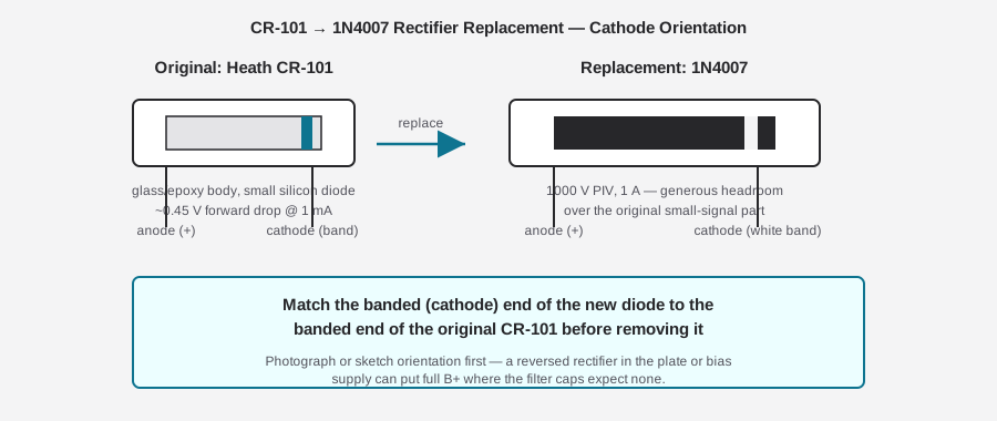
⚠ Danger — A reversed rectifier can present unfiltered AC or reversed DC to circuitry downstream that expects clean, correctly-polarized filtered DC — including, eventually, the socket pins a test tube sits in. Double-check polarity before power-up, every time.
5.5 The AC (Filament-Current) Capacitor — the Instrument’s Known Hazard
If there is one component on this instrument that deserves attention above all others, it is the 3-section AC capacitor that sets the constant-current filament/heater drive modes (300 / 450 / 600 mA, for series-string heater tubes). This is not a generic “recap while you’re in there” item — it is a known age-related failure mode with a real safety consequence for whatever tube happens to be socketed when it fails.
5.5.1 Why this capacitor is dangerous specifically as it ages
The TT-1’s constant-current heater drive works by putting this capacitor’s reactance in series with the heater circuit — the capacitance value, at line frequency, sets how much current the heater path can draw regardless of the tube’s own heater resistance. That is a clever piece of 1959 engineering for testing series-string (AC/DC set) tubes whose heaters are meant to run at a set current rather than a set voltage.
The problem is what happens to paper/foil AC capacitors as they age: capacitance tends to rise, not fall, as the dielectric degrades — and Kent Nickerson’s refurbishment notes describe values on real units rising enough to triple the intended filament current. A heater driven at three times its rated current will glow far brighter than normal, shorten (or destroy) the tube under test almost immediately, and can overheat the capacitor itself badly enough to cause visible bulging or venting.
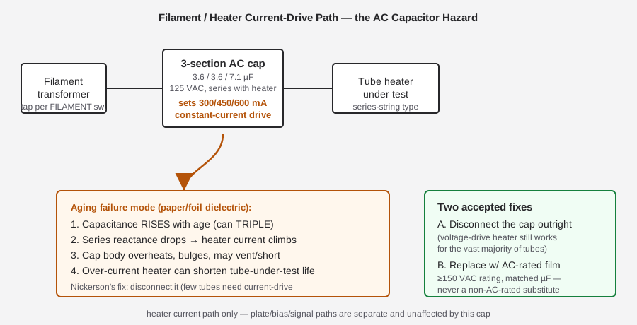
⚠ Danger — An aged AC filament capacitor is a hazard to the tube under test, not just to the instrument — a good, valuable NOS tube can be cooked in seconds by an over-current heater. If you are testing tubes on a TT-1 that has not had this specific component checked or serviced, treat every current-drive filament position with suspicion until verified.
5.5.2 Nickerson’s fix: disconnect it
The pragmatic fix used in the primary refurbishment report referenced throughout this volume is simply to disconnect the 3-section AC capacitor. The reasoning: the constant-current drive modes exist to serve a narrow category of series-string heater tubes, and the vast majority of tube types tested on a typical bench are handled fine by the instrument’s standard voltage-drive heater positions. Disconnecting removes the failure mode entirely at the cost of losing a feature that most users will rarely need.
5.5.3 If you want to keep the feature: AC-rated film replacement
If current-drive testing of series-string heater tubes matters to your bench work, replace the capacitor rather than deleting it — but only with a capacitor explicitly rated for AC service:
- Voltage rating ≥ 150 VAC — non-AC-rated (DC-only) film capacitors are not built to handle continuous AC ripple current and can themselves fail in the same overheating mode.
- Polystyrene or polypropylene film, matched as closely as practical to the original three section values (3.6 / 3.6 / 7.1 µF).
- Never substitute a generic DC electrolytic or a non-AC-rated film part “because the value is close” — this is exactly the kind of substitution that reintroduces the original hazard in a different form.
⚠ Danger — Do not “test and see” whether a suspect AC capacitor is still good by running current through it and watching for smoke. Measure its capacitance out of circuit against the original marked value first; if it has drifted meaningfully high, treat it as failed regardless of whether it looks physically intact.
5.6 Resistors, Switches, Pots, and Sockets
5.6.1 Resistors — check in situ, and watch for R20
Carbon composition resistors of this era drift high with age far more often than they drift low. Most of the resistors in the TT-1 are ordinary 10%-tolerance carbon parts; the precision (1%) resistors associated with the calibration circuit are generally still within spec even on tired units, because precision parts of this era were typically wound or selected to tighter, more stable construction.
- Check resistors in situ with power off before assuming a replacement is needed.
- Replace out-of-tolerance parts with metal-film resistors of equal or greater wattage — modern metal film is both more stable long-term and easier to source in tight tolerances than period-correct carbon composition.
- Recheck values after any nearby soldering — heat from an adjacent joint can shift a marginal resistor’s reading, so a resistor that measured fine before you touched the board next to it is worth a second look afterward.
A specific, commonly-reported casualty on this instrument is R20, which burns out often enough to be worth calling out by designator. The typical trigger is a shorting tube under test — a tube with an internal short can dump excess current through the measurement path, and R20 sits in a position that takes the brunt of it. If a TT-1 arrives with a specific function dead (rather than a general “everything’s weak” symptom), check R20 before assuming a more exotic fault.
Table 6 — 6.1 Resistors — check in situ, and watch for R20
| Failure trigger | What happens | What to check |
|---|---|---|
| Shorted or gassy tube inserted and tested | Excess current through the measurement path | R20 — check continuity/value before reinstalling any test tube |
| General age/drift, no specific event | Slow upward creep in 10% carbon resistors | Spot-check resistors in the plate/bias/signal paths against schematic values |
5.6.2 Switches and pots — the DeoxIT pass
The pin-selector rotary bank, the P/G/K bus switches, LEAKAGE selector, PLATE, BIAS RANGE, SIGNAL, METER, FILAMENT, and the SET LINE and METER pots all see mechanical wear and contact oxidation over decades of storage and use.
Procedure:
- Apply DeoxIT D5 to switch contacts and pot windings, working the control through its full range repeatedly to distribute the cleaner and mechanically scrub the contact surfaces.
- Follow with DeoxIT Gold on switches/contacts that see infrequent use, for longer-term protection.
- Gently scrub rheostat windings (LINE SET, METER) — these are wire-wound and can tolerate light mechanical cleaning better than a sealed pot, but avoid aggressive abrasives that could nick the winding.
- Exercise every switch and pot through its full range multiple times after cleaning, both to seat the cleaner and to catch any control that stays intermittent.
⚠ Danger — Replace, don’t just clean, any switch or pot that remains intermittent after a DeoxIT pass. An intermittent contact in the pin-selector or P/G/K bus can misroute plate or bias voltage to the wrong tube element mid-test — at best a bad reading, at worst damage to the tube under test.
5.6.3 Sockets
Worn 7-pin and 9-pin miniature sockets are a known cause of false low readings on this instrument — unsurprising given how much of the post-war tube population these two families cover, and therefore how much wear those two sockets accumulate relative to the less-used pin counts.
- Clean socket pins with isopropyl alcohol and a pipe cleaner sized to the socket.
- Check spring tension on each socket’s contacts by feel with a spare pin or a dead tube — a socket that doesn’t grip firmly is a candidate for contact or full socket replacement.
- Replace contacts or the full socket assembly on any position showing spread, corroded, or loose-fitting contacts, prioritizing the 7-pin and 9-pin miniature positions first.
5.6.4 A note for TT-1A units: the TTA-1-1 adapter
If the unit on the bench is a TT-1A — a TT-1 fitted with the TTA-1-1 socket adapter — remember what that designation actually means before treating it as a different circuit to service (Vol 1 covers this correction in full): it is a stock TT-1 with a 12-pin Compactron socket and a Nuvistor socket added, mounted in the case lid, tapping the existing pin-selector switch bus through minor added wiring. There is no separate power supply, oscillator, or measurement circuit associated with the adapter — every procedure in §1–§8 above applies identically to a TT-1A’s main chassis.
The only adapter-specific items to check during a refurb:
- The added wiring runs between the lid-mounted adapter sockets and the main switch bus — inspect these for the same cracked-insulation and cold-joint issues as the rest of the chassis wiring, since they were a later field/factory addition rather than part of the original 1959 build.
- The Compactron and Nuvistor sockets themselves — being a later addition, they’re less likely to show the same multi-decade wear as the original 7-pin/9-pin miniature sockets, but confirm spring tension and clean contacts the same way as §6.3.
- No separate calibration step — the adapter doesn’t add its own reference or require its own CALIBRATE pass; §8’s BIAS/SIGNAL/METER sequence covers the whole instrument, adapter included.
5.7 The Meter
The single large illuminated panel meter is, happily, one of the more durable subsystems in this instrument — the movement and the transformers feeding it are generally the parts most likely to have survived six decades intact. Service here is usually cleaning and mechanical adjustment rather than replacement.
- Clean the meter glass/bezel and check for any obstruction to needle movement.
- Re-zero mechanically — with the unit powered off and the meter level, use the mechanical zero adjust (typically a small screw below the meter face) to bring the needle to true zero.
- If the movement itself is sluggish, sticky, or shows visible damage to the pointer or scale, that is the exception to “usually fine” — a damaged movement is a parts-hunt problem, not a cleaning problem, and original TT-1 meters are not a trivial part to source. Exhaust cleaning and mechanical adjustment fully before concluding the movement itself is bad.
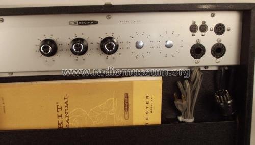
5.8 Calibration — the Self-Contained CALIBRATE Switch
This is the feature that sets the TT-1 apart from a simpler service-bench tube tester, and it is the step that makes the rest of this refurbishment meaningful: after the recap and repair work above, the instrument calibrates itself. There is no NOS reference tube to hunt down, no external precision voltmeter or signal generator required, and no factory-only adjustment that a home bench can’t perform.
5.8.1 Why no reference tube is needed
The CALIBRATE switch routes the meter to read against a set of precision components built into the instrument itself — anchored by the 0.22 µF, 2% capacitor discussed in §3.3, along with matched precision resistors. Because the reference is internal and precision-grade, the calibration procedure nulls the meter and the oscillator against known-good internal standards rather than against an external tube whose own characteristics could drift or vary between “reference” samples — a real limitation of tube-standard calibration schemes on other instruments.
5.8.2 BIAS / SIGNAL / METER procedure
The CALIBRATE switch has three positions, stepped through in sequence. Each step adjusts a specific subsystem against the internal precision reference until the meter reads at its index mark.
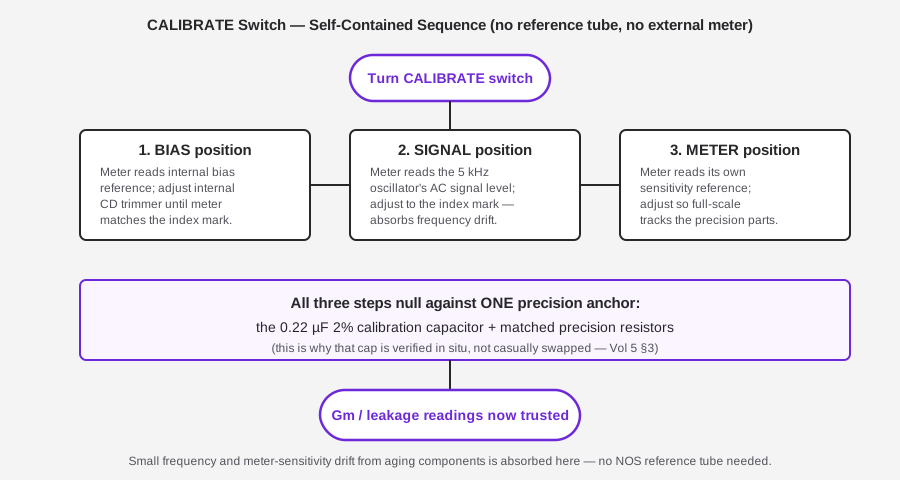
Table 7 — 8.2 BIAS / SIGNAL / METER procedure
| Step | CALIBRATE position | What it nulls | Adjustment |
|---|---|---|---|
| 1 | BIAS | Internal bias-supply reference against the precision cap/resistor network | Internal CD trimmer, adjusted until the meter matches the index mark |
| 2 | SIGNAL | The 5 kHz oscillator’s AC signal amplitude | Adjusted to the index mark — this is what compensates for the oscillator frequency-setting cap’s ±25% tolerance (§3.3) and for real-world frequency drift (Nickerson measured 7 kHz against a nominal 5 kHz on his own unit) |
| 3 | METER | The meter movement’s own sensitivity/scaling | Adjusted so the meter’s full-scale response tracks the precision reference |
Full transformer-voltage and instrument-tube (3A4, 12AV6) voltage check tables exist in the assembly and operating manuals for a deeper verification pass beyond the front-panel CALIBRATE steps — consult those directly if a calibration pass doesn’t resolve a suspected drift issue, since that points toward a supply or tube fault rather than a simple calibration adjustment.
5.8.3 What calibration can and cannot fix
Calibration absorbs small, expected drifts — a frequency that’s crept from 5 kHz toward 7 kHz, a meter sensitivity that’s shifted slightly, a bias reference that’s off by a small margin. It is not a substitute for the repair work in §3–§7. A unit with a genuinely failed rectifier, a leaky filter cap, or an out-of-tolerance resistor in the measurement path will not calibrate its way to accurate readings — the CALIBRATE switch has a limited adjustment range, and forcing it to compensate for a real component failure either won’t reach the index mark at all, or will “calibrate” against a moving target that drifts again as soon as the underlying fault progresses.
Practical order of operations: do the full recap and repair pass first (§3–§7), then run the CALIBRATE sequence as the final step before returning the instrument to service. Running CALIBRATE on a unit with unaddressed component faults wastes time and can mask a problem that will resurface later.
⚠ Danger — If the CALIBRATE switch cannot bring any of the three steps to its index mark within a reasonable adjustment range, stop and treat it as a symptom of an unrepaired fault upstream (§3–§7), not as a calibration-circuit problem to force through.
5.8.4 Verifying the precision components before you trust CALIBRATE
Because the whole self-calibration scheme leans on a handful of precision parts staying precise, it’s worth a direct verification pass on those specific components before relying on a clean CALIBRATE run as proof that everything is healthy:
Table 8 — as proof that everything is healthy
| Component | How to verify | What “good” looks like |
|---|---|---|
| 0.22 µF, 2% calibration cap | Out-of-circuit (or in-circuit, isolated) capacitance measurement | Reads within 2% of 0.22 µF — i.e., roughly 0.2156–0.2244 µF |
| Precision resistors in the calibration network | In-circuit resistance check against schematic values, powered off | Within the marked tolerance (typically 1%) — these are usually the most stable parts on the whole chassis |
| CALIBRATE switch contacts themselves | Visual + continuity check through each position | Clean, low-resistance contact at BIAS/SIGNAL/METER — a dirty CALIBRATE switch will itself cause a false “can’t hit the index mark” symptom that looks like a component fault |
If the 0.22 µF cap or the precision resistor network measure out of spec, that’s the rare case where replacing a precision part is warranted — but source a genuine 2%-tolerance replacement, not a generic-tolerance substitute, or the calibration circuit’s whole premise (a stable, known-good internal reference) is compromised.
5.9 Failure-Mode Reference
A consolidated table for triage and parts-buying, gathering the failure modes discussed above with their root cause and the accepted fix.
Table 9 — 9. Failure-Mode Reference
| Failure mode | Cause | Fix | Section |
|---|---|---|---|
| Weak, drifting, or absent plate/bias DC | Failed CR-101 silicon rectifier | Replace with 1N4007, matching cathode-band orientation | §4 |
| Ripple, hum, or pinning meter with power applied | Failed/leaky electrolytic filter cap | Replace all electrolytics, ≥ original V, up to ~2× µF, 105 °C parts | §3.1 |
| Erratic or drifting readings without an obvious hard fault | Leaky/drifted paper-wax coupling cap | Replace with film/ceramic, ≥ original V, within ~25% of value | §3.2 |
| Heater glows unusually bright / tube dies fast on current-drive settings | Aged 3-section AC filament capacitor risen in value (up to 3×) | Disconnect (Nickerson’s fix), or replace with AC-rated (≥150 VAC) film | §5 |
| A specific function goes dead after testing a bad tube | R20 burned out, triggered by a shorted/gassy tube | Check/replace R20; inspect the tube that triggered it | §6.1 |
| Slow overall accuracy drift across many tube types | General carbon-resistor drift (usually upward) | Spot-check resistors in situ; replace out-of-tolerance with metal film | §6.1 |
| Intermittent readings, worse when the case is tapped or a control is moved | Dirty/worn switch, pot, or socket contact | DeoxIT pass; exercise controls; replace any that stay intermittent | §6.2, §6.3 |
| Consistently low readings on 7-pin or 9-pin miniature tube types specifically | Worn/spread socket contacts on those two heavily-used families | Clean pins; replace contacts/socket if spring tension is gone | §6.3 |
| Meter reads off-zero with the unit powered off | Mechanical zero drifted | Adjust mechanical zero screw | §7 |
| Gm/leakage readings off by a small, consistent offset from chart figures | Normal aging drift in the oscillator frequency or meter sensitivity | Run the CALIBRATE BIAS/SIGNAL/METER sequence | §8 |
| CALIBRATE steps won’t reach the index mark | An unrepaired fault upstream (rectifier, filter cap, resistor) rather than a calibration-circuit problem | Re-check §3–§7 before re-attempting calibration | §8.3 |
5.10 Recap Parts List — Buying Notes
This is not a full bill of materials (exact quantities and designators are in the schematic/parts list referenced in the manual) — it is a shopping-list-shaped summary of what to have on hand before starting the teardown, organized by the sections above.
Table 10 — 10. Recap Parts List — Buying Notes
| Part class | Spec to buy | Approx. quantity needed | Notes |
|---|---|---|---|
| Electrolytic filter caps, plate supply | ≥350 V, ~20–40 µF, 105 °C | 3 (matching the original bank) | Verify physical fit against chassis mounting |
| Electrolytic filter cap, plate supply | ≥150 V, ~40–80 µF, 105 °C | 1 | |
| Electrolytic filter cap(s), bias supply | Per schematic, ≥ original V | As needed | |
| Film/ceramic coupling caps | Various values per schematic, ≥ original V | Whole-instrument sweep — expect a dozen-plus small caps | Within ~25% of original marked value is fine |
| Silicon rectifier diodes | 1N4007 (1000 V / 1 A) | Matches count of original CR-101s | Cheap enough to buy extras |
| AC-rated film capacitor (if replacing rather than disconnecting the filament cap) | ≥150 VAC, polystyrene/polypropylene, matching 3.6/3.6/7.1 µF sections | 1 (3-section, or 3 discrete) | Skip entirely if choosing the disconnect fix |
| Metal-film resistors | Values as measured out-of-tolerance during triage, equal or greater wattage | Variable — budget for R20 specifically | Don’t buy blind; measure in situ first |
| Contact cleaner | DeoxIT D5 + DeoxIT Gold | 1 can/bottle each | Covers the whole switch/pot/socket pass |
⚠ Danger — Do not substitute a lower-voltage-rated part anywhere in this list “because it’s what’s in the parts bin.” The voltage headroom recommendations above exist because this instrument’s plate supply reaches 225 VDC, and an undersized part is a latent failure waiting for the day someone leaves the PLATE switch at its highest position.
5.11 Post-Recap Bring-Up and Verification
Once the recap, rectifier, AC-cap, resistor, contact-cleaning, and calibration work is complete, bring the unit back into service methodically rather than immediately socketing an expensive NOS tube.
- Variac ramp-up again, watching current draw, smell, and heat exactly as in §2.2 — a post-recap unit deserves the same caution as an unknown one on its first power-up, because a cold solder joint or a reversed part from the rework itself is a real (if less likely) possibility.
- No tube inserted, verify plate DC at each PLATE switch position against the manual’s verification table (nominal 26 / 90 / 135 / 225 VDC at positions O/C/D/F) with a DMM at the socket bus — see the full position table below.
- Verify bias DC across its 0–20 V range on both the L and H BIAS RANGE positions.
- Run the CALIBRATE sequence (§8) and confirm all three steps reach their index marks within a normal adjustment range.
- Test a known-good tube first — something common and expendable, not the prize NOS bottle — and compare the Gm reading against the roll chart’s minimum figure for that type (Vol 4 covers the full setup-and-grading procedure). A reading in a sane, stable range confirms the instrument end-to-end.
- Only then move to valuable or unknown tubes.
PLATE switch verification points, for reference during step 2 — nominal values, no tube socketed, line voltage set to the SET LINE index mark:
Table 11 — socketed, line voltage set to the SET LINE index mark
| PLATE switch position | Nominal output | Type |
|---|---|---|
| O | 26 V | DC |
| C | 90 V | DC |
| D | 135 V | DC |
| F | 225 V | DC |
| A | 20 V | AC |
| B | 45 V | AC |
| E | 177 V | AC |
| G | 0–200 V, variable | DC (VR-tube test range) |
A reading meaningfully off any of these nominal figures with no tube in the socket — after the recap and rectifier work in §3–§4 — points back to that specific tap on the plate supply rather than to the instrument as a whole, which narrows the fault-finding considerably versus a blanket “readings are off” symptom.
5.12 The Two-Tester Bench, Post-Refurbishment
A refurbished, calibrated TT-1 earns its keep specifically because it measures something the companion Supreme 385 emission tester cannot: transconductance, the actual figure of merit for gain, rather than raw cathode emission. None of that matters if the instrument itself is drifting or lying — which is the whole case for treating this refurbishment as a real project rather than a “plug it in and see” exercise. A tube tester with an unrepaired rectifier, a leaky coupling cap, or an over-current filament drive isn’t just less accurate than a healthy TT-1 — it can actively damage the tubes it’s meant to be evaluating, undermining the entire premise of a two-tester bench. Vol 6’s cheatsheet ties the emission-vs-Gm comparison together once both instruments in the pair are trusted to read straight.
Sources
Primary / hands-on refurbishment reference:
- Kent Nickerson, “Refurbishment and Verification of the Heathkit TT-1 Tube Tester” — https://paulcarbone.com/blog/wp-content/uploads/2020/06/TT1_Refurbishment.pdf
Manuals and schematics:
- Heathkit TT-1 Operation/Assembly manual (OCR), rsp-italy.it mirror — https://www.rsp-italy.it/Electronics/Kits/_contents/Heathkit/Kits/Heathkit%20TT-1%20Tube%20tester%20Manual.pdf
- Internet Archive — Heathkit TT-1 Gm Tube Tester: https://archive.org/details/Heathkit_TT-1_Gm_Tube_Tester
- Internet Archive — Heathkit TT-1A schematic: https://archive.org/details/Heathkit_TT-1A_Tube_Tester_schematic
- Internet Archive — Heathkit TT-1A (TTA-1-1 socket-adapter assembly manual): https://archive.org/details/Heathkit_TT-1A_Tube_Tester
- Internet Archive — Heathkit TT-1 Tube Tester data: https://archive.org/details/Heathkit_TT-1_Tube_Tester_data
- Tube-data supplement (Nov 1978): https://www.pestingers.net/pdfs/heathkit-test/t1a-supplemental-78.pdf
Museum and reference:
- Heathkit Virtual Museum — TT-1: https://heathkit-museum.com/test/hkTT-1.html
- RadioMuseum — Heath Tube Tester TT-1: https://www.radiomuseum.org/r/heath_tube_tester_tt_1_tt.html
- Alan Douglas, Tube Testers and Classic Electronic Test Gear (ISBN 1886606145)
- RDF Products application note (VR_APL_004), TT-1A chassis figures: http://www.rdfproducts.com/vr_apl_004.pdf
Photo credit: front-panel and internals photography by radiomuseum.org (see figure captions).