Heathkit TT-1 Tube Tester · Volume 6
Heathkit TT-1 — Vol 6: Cheatsheet & Emission vs Gm — the Two-Tester Bench
The laminate-ready card — quick specs, the roll-chart-to-µmhos operating sequence, the refurb order, the safety envelope, and the emission-vs-Gm comparison that is the whole point of running this tester alongside the Supreme 385
6.1 What This Volume Is For
Vols 1–5 taught the instrument in depth: what it is and why it exists (Vol 1), how the dynamic Gm test actually works (Vol 2), what is inside this specific unit (Vol 3), how to set one up and grade a tube (Vol 4), and how to refurbish and self-calibrate it (Vol 5). This closing volume is the bench card — dense tables meant to be printed, laminated, and clipped next to the tester, plus the section that makes this a pair rather than two unrelated instruments: a rigorous comparison of the TT-1’s dynamic mutual-conductance (Gm) method against the Supreme 385’s DC emission method. Every row below carries a “detail: Vol N §” pointer back to the volume that derives it — this card is a summary, not a replacement, for that material.
6.2 Quick-Facts Panel
Table 1 — 1. Quick-Facts Panel
| Item | Value | Detail |
|---|---|---|
| Model | Heathkit TT-1 “Mutual Conductance Tube Tester” (TT-1A = TT-1 + TTA-1-1 socket adapter, not a circuit revision) | Vol 1 §1 |
| Maker | Heath Company, Benton Harbor, Michigan — solder-it-yourself kit | Vol 1 §1 |
| Era | Kit released circa 1959–1960; catalog presence through ~1973; tube-data supplements issued through Nov 1978 | Vol 1 §1 |
| Lineage | Kit-form redesign of the professional Weston Model 981 (Type 3 / 981-3); Daystrom owned both Weston and Heath | Vol 1 §2 |
| Test class | True dynamic mutual-conductance (Gm) tester — not an emission tester (compare Heath’s own TC-1/TC-2/TC-3 line, which are emission testers) | Vol 1 §3, Vol 2 §1 |
| Physical | Portable, wood/covered carrying case, ~17.75–18 in × 13.5 in × 7.5–8.5 in (sources vary slightly) | Vol 3 §1 |
| Power | AC line, 105–125 V, 60 Hz; fused | Vol 3 §4 |
| Primary readout | Gm directly in µmhos, 0–3000 direct scale, to ~24,000 µmhos with multipliers | Vol 2 §1, Vol 3 §1 |
| Instrument tubes (only two active devices besides the meter) | 3A4 — 5 kHz grid-signal oscillator; 12AV6 — grid-current/gas detector | Vol 2 §2, Vol 3 §4 |
| Rectifiers | Silicon, Heath part CR-101, in the plate and bias DC supplies — no selenium HV stack | Vol 3 §4, Vol 5 §3 |
| Setup mechanism | Illuminated roll chart built into the main panel (no separate drawer) + per-pin rotary selector switches + P/G/K bus switches | Vol 3 §3, Vol 4 §1 |
| Sockets, built-in | 4-, 5-, 6-, 7-pin large, 7-pin miniature, 7-pin sub-miniature, 8-pin sub-miniature (loctal region), octal, loctal, 9-pin miniature, plus blank/spare sockets | Vol 3 §2 |
| Sockets, TT-1A adds | 12-pin Compactron, Nuvistor (via the TTA-1-1 lid-mounted adapter, ~1962) | Vol 1 §1, Vol 3 §2 |
| Also tests | Shorts/leakage (0–10 MΩ) · grid current/gas (12AV6, ¼ µA sensitivity) · life test (heater −10%) · VR-tube regulation (0–200 V) · diode O.K./Reject | Vol 2 §3 |
| Calibration | Self-calibrating — CALIBRATE switch (BIAS/SIGNAL/METER positions); no reference tube or external test gear needed | Vol 5 §6 |
| Original kit price | NOT FOUND in any period catalog source consulted; a period Heathkit catalog ad (see figs/ad_catalog.jpg) shows $134.50 — cite that only as a period catalog figure, not a confirmed original list price, and never cite modern resale prices (~$499 seen at retro-sellers) as the original price | Vol 1 §1 |
6.3 What This Unit Tests
Table 2 — 2. What This Unit Tests
| Function | What it reads | Range / sensitivity | Detector / mechanism | Detail |
|---|---|---|---|---|
| Mutual conductance (Gm) | µmhos, direct | 0–3000 µmhos direct; to ~24,000 µmhos with multipliers | Tube biased at a real DC operating point (plate up to 225 V, filtered bias 0–20 V, rated heater); a 5 kHz AC signal from the 3A4 oscillator is injected on the grid; meter reads the resulting AC plate-current swing scaled to µmhos | Vol 2 §1–§2 |
| Shorts / leakage | Megohms, direct-reading ohmmeter | 0–10 MΩ | LEAKAGE switch selects 5 pin-pair combinations (e.g. 4-7, 2-7, 5-7, 6-7, 1-7) | Vol 2 §3 |
| Grid current / gas | GOOD/gassy indication | ¼ µA sensitivity | 12AV6 as dedicated grid-current detector tube; high grid current flags gas or grid emission | Vol 2 §3, Vol 3 §4 |
| Life test | Gm droop under stress | Heater cut ~10% (momentary switch) | A tube whose Gm collapses when the heater is knocked down is flagged as marginal even if it reads acceptable Gm at full heater | Vol 2 §3 |
| Voltage-regulator (VR) tubes | Regulation voltage | 0–200 V | PLATE switch position G (variable DC) feeds the VR tube; meter reads regulated output | Vol 2 §3 |
| Diode / rectifier | O.K. / Reject | Meter zone marked DIODES O.K. | Emission-style DC check specific to diode and rectifier tube types | Vol 2 §3 |
| Auxiliary provisions | — | — | Hybrid/auto-radio series-heater provision; space-charge-grid supply (26 V); handles low-power thyratrons and electron-ray (“magic eye”) tubes | Vol 2 §3, Vol 3 §4 |
⚠ Danger — Every function above except leakage/shorts runs the tube under real bias with plate voltages to 225 VDC present on exposed sockets, selector contacts, and test leads while a tube is seated. Treat any TT-1 with the cover off and line cord in as live. See §6 below and
../_shared/legal_ethics.md.
6.4 Operating Quick-Steps — Roll Chart to µmhos Reading
The condensed version of the full walk-through in Vol 4 §1–§2. Do the steps in order; do not skip the leakage/shorts check before applying Gm bias to an unknown tube.
┌──────────────────────────────────────────────────────────────────────────┐
│  TT-1 OPERATING SEQUENCE                                                  │
├──────────────────────────────────────────────────────────────────────────┤
│  1  SCROLL THE ROLL CHART (thumb-wheels, either side) to the tube type.   │
│     Read off: pin-selector code, P/G/K bus positions, PLATE, BIAS RANGE,  │
│     FILAMENT tap, SIGNAL level, METER range, and the reject/minimum Gm.   │
│  2  SET THE PER-PIN SELECTOR SWITCHES to the chart code — top row pins    │
│     1–5 (left→right), bottom row pins 6–9. Set the P / G / K bus          │
│     switches to route the element under test for THIS section.           │
│  3  SET FILAMENT (heater V/A tap), PLATE (voltage position A–G), BIAS     │
│     RANGE (L/H) + BIAS pot, and SIGNAL (2 / 1 / 0.5 / 0.25 V) per chart.  │
│  4  SEAT THE TUBE. Let the heater stabilize (tube warms up — do not rush  │
│     a Gm reading on a cold tube).                                         │
│  5  SET LINE — adjust the SET LINE control against the LINE CHECK meter   │
│     position until it reads on the reference mark. This calibrates the   │
│     line voltage the whole test depends on; skip it and every downstream  │
│     reading drifts with wall voltage.                                     │
│  6  CHECK LEAKAGE — step the LEAKAGE switch through its pin pairs; meter  │
│     should stay near 0 (infinite Ω) unless the chart calls for a normal   │
│     internal leakage path on that type.                                   │
│  7  PRESS/HOLD THE Gm TEST lever — read µmhos directly off the 0–3000     │
│     scale (apply METER multiplier if the chart calls for one).            │
│  8  COMPARE the reading to the chart's printed minimum-Gm reject figure.  │
│     At or above minimum = passes on Gm. Below = weak/reject.              │
│  9  FOR MULTI-SECTION TUBES (dual triodes, etc.) repeat from step 2 with  │
│     the P/G/K bus switches moved to the next section — the rest of the    │
│     panel settings usually carry over from the same chart line.          │
│ 10  OPTIONAL CHECKS per chart: GRID CURRENT (gas), LIFE TEST (heater      │
│     droop), DIODE O.K./Reject zone, VR regulation (PLATE pos. G).         │
└──────────────────────────────────────────────────────────────────────────┘
Note the shape of that flow: everything through step 6 is setup, and only step 7 is the actual Gm measurement. Most bad readings on this tester trace back to a chart-transcription slip in steps 1–3, not a fault in the tube — recheck the chart line before condemning a tube on a marginal reading. Detail: Vol 4 §1–§2.
6.5 Front-Panel Control Quick Reference
Table 3 — 4. Front-Panel Control Quick Reference
| Control | Purpose | Typical range / positions | Detail |
|---|---|---|---|
| Roll chart + thumb-wheels | Look up per-tube settings and the reject-Gm minimum | Illuminated, built into panel, free-rolling | Vol 3 §3 |
| Pin selector switches (×9) | Route filament/plate/screen/grid to the correct socket pins | One rotary switch per pin, top row 1–5 / bottom row 6–9 | Vol 3 §3 |
| P / G / K bus switches | Select which internal element (plate / grid / cathode) the measurement connects to, for testing one section of a multi-section tube | 3 switches | Vol 3 §3, Vol 4 §3 |
| SET LINE | Continuously variable line-voltage trim, checked against LINE CHECK | Calibrates test voltages to actual wall voltage | Vol 4 §1 |
| FILAMENT | Heater voltage/current tap, including constant-current 300/450/600 mA positions for series-string heaters | Multiple taps | Vol 3 §4 |
| PLATE | DC plate voltage selector (positions A–G) plus AC test positions | DC: 26 / 90 / 135 / 225 V (O/C/D/F); AC: 20 / 45 / 177 V (A/B/E); G = variable DC for VR test | Vol 3 §4 |
| BIAS RANGE + BIAS pot | Filtered negative DC grid bias | 0–20 V, two ranges (L/H) | Vol 3 §4 |
| SIGNAL | AC grid test-signal amplitude from the 5 kHz oscillator | 2 / 1 / 0.5 / 0.25 V AC | Vol 2 §2 |
| METER | Sensitivity / range multiplier for the Gm scale | Extends 0–3000 µmhos up to ~24,000 µmhos | Vol 3 §1 |
| LEAKAGE | Selects pin pair for the shorts/leakage ohmmeter | 0–10 MΩ, 5 selectable pairs | Vol 2 §3 |
| DISCONNECT | Isolates the tube-under-test circuit (safety/setup convenience) | On/off | Vol 4 §1 |
| LIFE TEST | Momentary heater-droop stress switch | ~10% heater reduction | Vol 2 §3 |
| GRID CURRENT | Engages the 12AV6 gas/grid-current detector | ¼ µA sensitivity | Vol 2 §3, Vol 3 §4 |
| Gm test lever | Momentary — takes the actual Gm reading | Press/hold to read | Vol 4 §1 |
| CALIBRATE | Self-calibration switch: BIAS / SIGNAL / METER positions | No reference tube or external meter needed | Vol 5 §6 |
6.6 Refurb Quick Order
Condensed from Vol 5, which cites Kent Nickerson’s hands-on TT-1 refurbishment report as the primary source. Work in this order; each step assumes the prior ones are done.
Table 4 — 5. Refurb Quick Order
| # | Step | What / why | Detail |
|---|---|---|---|
| 1 | Fuse first | Confirm the correct fuse rating is fitted before applying power to a long-stored unit — do not power up on a wrong or bridged fuse “to see what happens” | Vol 5 §1 |
| 2 | Recap the supplies | Replace all electrolytics (supply-filter types) with parts rated ≥ original voltage; up to ~2× original capacitance is acceptable; prefer 105 °C parts for longevity | Vol 5 §2 |
| 3 | Recap the coupling caps | Replace paper/wax (black plastic tubular) AC-coupling caps with film or ceramic, ≥ original voltage, within ~25% of the marked value | Vol 5 §2 |
| 4 | Leave the two precision caps alone unless proven bad | The 0.22 µF 2% calibration cap (behind CALIBRATE) and the 0.02 µF 600 V frequency-setting cap (sets the ~5 kHz signal) — verify in situ; the frequency cap’s ±25% tolerance is fine because the self-calibration step absorbs it | Vol 5 §2 |
| 5 | Replace the rectifiers: CR-101 → 1N4007 | The original Heath CR-101 silicon diodes in the plate/bias supplies are not rugged and commonly fail; swap to 1N4007, matching cathode orientation to the original’s red-banded end | Vol 5 §3 |
| 6 | Deal with the AC filament capacitor | The 3-section AC cap that sets the 300/450/600 mA constant-current filament drives can rise in value with age, tripling filament current and overheating/bulging under load — a real hazard, not cosmetic. Nickerson’s fix: disconnect it (few tubes on the bench need current-drive heaters). If you replace it instead, use an AC-rated (≥150 VAC) polystyrene film part — never a non-AC-rated substitute | Vol 5 §4 |
| 7 | Check resistors in situ | Carbon-comp resistors drift high with age; verify and replace out-of-tolerance 10% parts with metal-film of equal wattage; recheck values after nearby soldering heat. Precision 1% parts are usually still in spec. Watch for R20, a known casualty often triggered by a shorting tube under test | Vol 5 §5 |
| 8 | Deoxit the switches, pots, sockets | Clean and exercise the slide switches, rotary pin selectors, and pots (LINE SET, METER); gently scrub rheostat windings; clean socket pins with a pipe cleaner. Replace anything that stays intermittent — an intermittent switch under a tube-under-test can damage the tube | Vol 5 §5 |
| 9 | Zero and clean the meter | Clean and mechanically re-zero; the movement itself generally survives decades of storage without replacement | Vol 5 §5 |
| 10 | Self-CALIBRATE | Run the CALIBRATE switch through BIAS / SIGNAL / METER positions — this is fully self-contained (no reference tube, no external voltmeter) and is what absorbs the small drifts left over from steps 4–9 (e.g. Nickerson measured his oscillator running closer to 7 kHz than the nominal 5 kHz — calibration, not a frequency-cap chase, is what corrects for that) | Vol 5 §6 |
⚠ Danger — Steps 2, 3, 5, and 6 require the chassis out of the case with the line cord capable of being reconnected for verification. Accessible points on this instrument carry up to a few hundred volts DC even during routine bench work. Discharge and verify filter caps with a meter before touching anything in the supply section — do not assume “unplugged” means “safe.”
6.7 Safety DON’Ts
This is a mains-powered, tube-era instrument with exposed high-impedance nodes at up to 225 VDC during normal use, not just during repair. Full bench-safety discipline is in ../_shared/legal_ethics.md; the TT-1-specific don’ts:
⚠ Danger — Do NOT power up after long storage without first checking the fuse and doing a slow variac ramp-up if the unit’s history is unknown — old electrolytics can fail explosively on a cold, full-voltage start.
⚠ Danger — Do NOT assume the AC filament capacitor is safe merely because the unit “worked last time.” Its known failure mode (rising capacitance → tripled filament current → overheating/bulging) develops with age and is present on this tester’s design regardless of use history. Verify or disconnect it per §5 step 6 before extended use.
⚠ Danger — Do NOT probe inside the chassis with the line cord plugged in “just to check one thing.” The plate supply reaches 225 VDC; the meter and switch bus carry it to multiple accessible points on the panel side of the chassis, not only deep inside.
⚠ Danger — Do NOT trust “switched off” as “safe.” Filter capacitors in the plate/bias supplies can hold a charge after power-down. Verify near-zero volts with a meter before reaching into the supply section, exactly as with any tube-era HV gear on this bench.
⚠ Danger — Do NOT leave an intermittent switch or pot in service. On this tester an intermittent P/G/K bus or pin-selector contact can dump unintended plate voltage onto the wrong tube element while a tube is seated — that risks the tube under test, not just the instrument.
⚠ Danger — Do NOT treat a shorting tube casually. A shorted tube under test is the documented trigger for the R20 resistor failure (§5 step 7); if a tube shows a dead short on LEAKAGE, resolve that before proceeding to Gm/plate voltages.
Do NOT swap the CR-101 replacement for a lower-voltage part “because it’s silicon anyway” — match or exceed the original PIV/current rating (1N4007 is the documented, verified substitute).
Do NOT skip the leakage/shorts check (§3 step 6) on an unknown tube before running Gm — it is cheap, fast, and catches the one failure mode (element-to-element short) that can otherwise damage the tester itself when full plate voltage is applied.
6.8 Emission vs Gm — The Two-Tester Bench
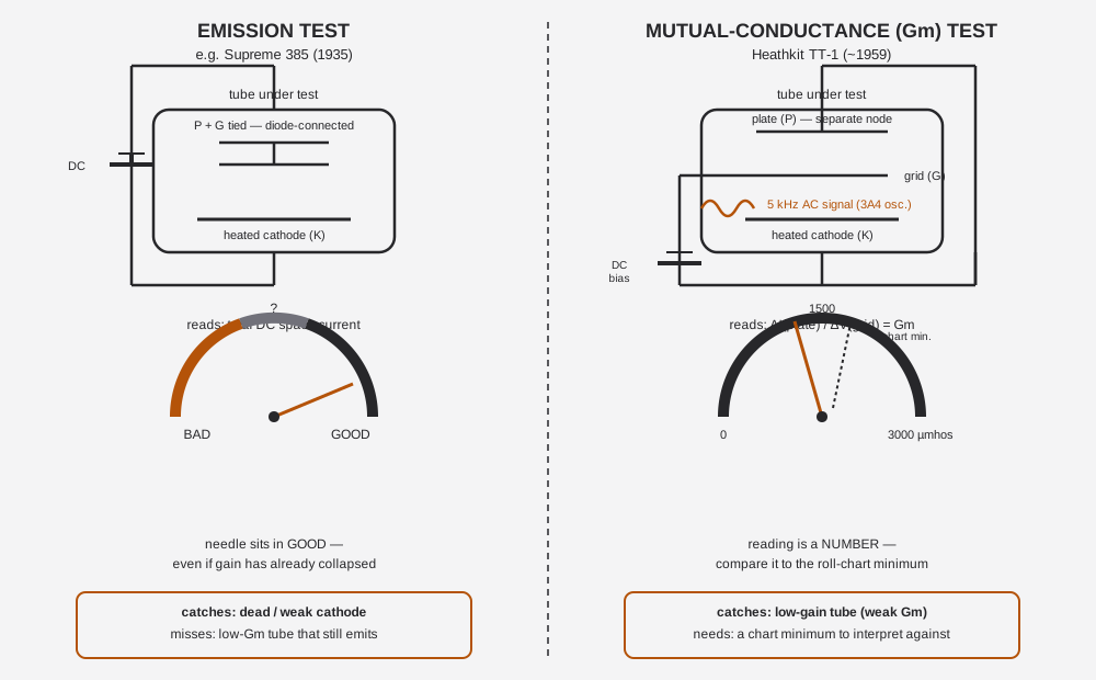
This is the section that makes Jeff’s pair of testers a matched set rather than two unrelated pieces of gear: the Supreme Instruments 385 Automatic (1935, DC emission) sitting next to the Heathkit TT-1 (~1959, dynamic Gm). Every vacuum-tube service bench of the mid-20th century eventually had to answer the same question the pair poses here — is a cheap, fast, operator-proof emission check good enough, or do you need the extra cost and complexity of a true transconductance test? The 1935 Supreme manual itself argues against building a Gm tester on cost/complexity grounds; twenty-four years later Heath shipped one as a kit anyone could solder together. That argument, and its resolution, is the whole point of running both testers on the same bench.
6.8.1 The core distinction
- Emission test (Supreme 385’s method): the tube under test is run diode-connected — plate and grid tied to one node — under approximately its rated load, with a single DC source. The meter reads the total DC cathode/space current flowing between that tied node and the cathode, and grades it against a GOOD/?/BAD arc. It answers one question: is the cathode still emitting electrons at roughly its rated rate?
- Mutual-conductance test (TT-1’s method): the tube is biased at a realistic separate operating point — DC plate voltage, DC negative grid bias, rated heater — with the plate and grid kept as distinct nodes. A small AC signal (5 kHz, from the 3A4 oscillator) is then injected onto the grid, and the meter reads the resulting AC swing in plate current, scaled directly to µmhos. It answers a different question: for a small wiggle on the grid, how much does the plate current actually respond — which is the direct definition of transconductance, Gm ≡ ΔI(plate)/ΔV(grid), and is the real figure of merit for gain.
The figure below sketches both signal paths side by side.
6.8.2 The comparison table
Table 5 — 7.2 The comparison table
| Dimension | EMISSION (Supreme 385) | Gm / mutual-conductance (Heathkit TT-1) | Detail |
|---|---|---|---|
| Era | 1935 | ~1959–1960 | Vol 1 §1 |
| What is physically measured | Total DC space current through a diode-connected tube under ~rated load | AC plate-current response to a small AC grid signal, at a real DC bias point | Vol 2 §1 |
| Signal path | DC only, single source | DC bias (plate + grid, separate) plus an injected 5 kHz AC test signal from a dedicated oscillator (3A4) | Vol 2 §1–§2 |
| Readout | GOOD / ? / BAD arc (qualitative zones) | Direct numeric scale, 0–3000 µmhos (to ~24,000 µmhos with multipliers) | Vol 3 §1 |
| How a result is judged | Read the needle’s zone directly off the meter face | Compare the number to the roll-chart’s printed minimum-Gm reject figure for that tube type — requires the chart and a lookup, not just a needle position | Vol 4 §2 |
| What it correctly catches | A cathode that has genuinely stopped emitting (dead or badly weakened tube) — fast, and hard for an inexperienced operator to misread | A tube whose gain (transconductance) has fallen, even though the cathode is still emitting current fine | Vol 2 §1 |
| What it misses | A tube with collapsed transconductance that still emits near its rated space current — this is the exact failure mode that reads falsely “GOOD” on emission but is already a weak/noisy/low-gain tube in a real circuit | Behavior at the tube’s true full-power operating current/dissipation (Gm testers measure small-signal response at a bench point, not full-load stress); microphonics, HF performance, and intermittents are not directly revealed either | Vol 2 §5.2 |
| Complexity of the test circuit | Low — one DC supply, one meter, diode-connected socket wiring | Higher — separate plate and bias supplies, a dedicated 5 kHz oscillator (3A4), a grid-signal injection path, and a meter circuit that must resolve a small AC component riding on the DC operating point | Vol 2 §2, Vol 3 §4 |
| Operator skill / interpretation load | Low — read a zone, done. Genuinely “operator-proof” as advertised | Higher — operator must set plate/bias/signal/filament correctly from the chart before the reading means anything, then compare the number against a printed minimum rather than trust a colored zone | Vol 4 §1–§2 |
| Relative speed on the bench | Fast — minimal setup once the socket is dialed in | Slower — full chart lookup and multi-control setup per tube, repeated per section on multi-section tubes | Vol 4 §3 |
| Relative cost / build complexity (period) | Cheap — the 1935 Supreme design explicitly argues against building a Gm tester on cost/complexity grounds | More expensive to build — Heath’s flagship kit-tester tier, with the oscillator, extra supply rails, and roll-chart mechanism the Supreme’s era considered not worth the cost | Vol 1 §2, Supreme 385 Vol 2 §1 |
| Self-calibration | Not a feature of the emission-tester class in general (period-dependent) | Built-in, switch-operated (CALIBRATE: BIAS/SIGNAL/METER) — no reference tube or external meter needed | Vol 5 §6 |
| Best use on the bench today | Fast go/no-go triage on a stack of pulled tubes, or a sanity check before a Gm test | The authoritative call on a tube that emission passed but a circuit still misbehaves with, or on any tube where gain (not just “is it dead”) is the question | §7.3 below |
6.8.3 What each catches, what each misses — in plain terms
- Emission passes tubes Gm would reject. A tube can still shove close to its rated DC current through a diode-connected test — enough to land the Supreme 385’s needle in “GOOD” — while its actual transconductance, the ΔI(plate)/ΔV(grid) that determines how much gain a real amplifier stage gets from it, has already fallen well below the chart minimum the TT-1 would flag. This is not a fringe case; it is the textbook failure mode that mutual-conductance testing was invented to catch, and it is exactly why Heath built the TT-1 as its flagship kit tester rather than another emission tester in the TC-1/TC-2/TC-3 line.
- Gm needs a chart and a number, emission doesn’t. The TT-1’s payoff (catching the low-Gm-but-still-emitting tube) comes with a cost the Supreme 385 does not have: the reading is meaningless on its own. 1800 µmhos is fine for one tube type and a reject for another — the operator must scroll to the correct roll-chart line, dial in the exact plate/bias/signal/filament settings the chart specifies, and then compare the resulting number to that chart’s printed minimum. Set up the wrong line, or misread the pin-selector code, and you get a wrong number with no colored zone to warn you something is off — a failure mode the diode-connected, zone-read Supreme 385 largely avoids by design.
- Neither catches everything. The Gm test is a small-signal measurement at one bench operating point; it does not stress the tube at its true full-power plate dissipation, so a tube marginal only under real load can still pass. Neither tester reveals microphonics, RF/HF performance, or intermittent faults directly — both are DC/low-frequency bench tools, not a substitute for in-circuit performance under the tube’s actual operating conditions.
- The historical argument the pair embodies. The 1935 Supreme manual makes an explicit cost/complexity case against building a dynamic Gm tester — extra oscillator, extra supply rails, extra operator training, for a test most service benches of the era judged not worth it against a fast, cheap, “good enough” emission check. The Weston 981-3 (1957) and its Heathkit-kit descendant, the TT-1 (~1959), are the industry’s answer a generation later: as tube circuits got more gain-critical and service techs got more sophisticated, the extra complexity became worth paying for. Running both testers side by side reproduces that debate on one bench, with both sides’ actual hardware.
6.8.4 Quick decision table
Table 6 — 7.4 Quick decision table
| If the question is… | Reach for | Why | Detail |
|---|---|---|---|
| ”Is this pulled tube stone dead or obviously weak?” | Supreme 385 (emission) | Fast, operator-proof, correct for gross cathode failure | §7.1 above |
| ”This circuit still misbehaves and the tube passed emission — is it actually the tube?” | Heathkit TT-1 (Gm) | Catches the low-Gm-but-still-emitting case emission cannot see | Vol 2 §1 |
| ”I need the transconductance figure to compare against a datasheet/roll-chart spec” | Heathkit TT-1 (Gm) | Only the TT-1 gives a µmhos number at all | Vol 3 §1 |
| ”I’m sorting a large box of pulls and just need a fast triage pass” | Supreme 385 first, TT-1 on the survivors | Emission is the cheaper first filter; Gm is the more expensive second opinion | §7.2 above |
| ”The tube passed both — am I done?” | Neither, fully | Both are bench small-signal/DC tests; neither confirms full-load, RF, or microphonic behavior in the actual circuit | §7.3 above |
Sources
- Heathkit TT-1 Operation/Assembly manual (OCR mirror): rsp-italy.it — https://www.rsp-italy.it/Electronics/Kits/_contents/Heathkit/Kits/Heathkit%20TT-1%20Tube%20tester%20Manual.pdf
- Internet Archive — Heathkit TT-1 Gm Tube Tester: https://archive.org/details/Heathkit_TT-1_Gm_Tube_Tester
- Internet Archive — Heathkit TT-1A schematic: https://archive.org/details/Heathkit_TT-1A_Tube_Tester_schematic
- Internet Archive — Heathkit TT-1A (TTA-1-1 socket-adapter assembly manual, 8-29-69): https://archive.org/details/Heathkit_TT-1A_Tube_Tester
- Internet Archive — Heathkit TT-1 Tube Tester data: https://archive.org/details/Heathkit_TT-1_Tube_Tester_data
- Tube-data supplement (Nov 1978): https://www.pestingers.net/pdfs/heathkit-test/t1a-supplemental-78.pdf
- Kent Nickerson, “Refurbishment and Verification of the Heathkit TT-1 Tube Tester” (PDF): https://paulcarbone.com/blog/wp-content/uploads/2020/06/TT1_Refurbishment.pdf
- Heathkit Virtual Museum — TT-1: https://heathkit-museum.com/test/hkTT-1.html
- RadioMuseum — Heath Tube Tester TT-1: https://www.radiomuseum.org/r/heath_tube_tester_tt_1_tt.html
- Alan Douglas, Tube Testers and Classic Electronic Test Gear (ISBN 1886606145)
- RDF Products application note (VR_APL_004), TT-1A chassis figures: http://www.rdfproducts.com/vr_apl_004.pdf
- Weston 981: http://www.vacuumtubes.com/981.html
- Weston 981 Type 3: https://vintagetubeelectronics.com/weston-981-type-3-tube-tester/
- Antique Radio Forums / narkive rec.antiques thread on the Weston 981-3 vs Heathkit TT-1 lineage: https://rec.antiques.radio-phono.narkive.com/idZqSxCH/weston-981-3-vs-heathkit-tt-1-tube-testers