PACO Z-80 Audio-RF Signal Tracer · Volume 1
PACO Z-80 — Vol 1: Overview — What the PACO Z-80 Is
A tube-era audio + RF signal tracer from PACO, and why it still earns bench space
1.1 The one-sentence version
The PACO Z-80 is a tube-era audio + RF signal tracer: a portable, high-gain amplifier with its own speaker and a magic-eye level indicator that you carry, probe in hand, through a live radio or TV chassis to find out where the signal still exists — and, by extension, where it has died. It is a diagnostic listening post, not a source. It does not make a signal; it follows one. That distinction is the whole point of the instrument, and it is worth nailing down on page one because the single most common mistake with this box is to expect it to inject a tone. It cannot. Signal generation lives in an entirely separate PACO product line — the G-30 / G-34 generators — and the Z-80 has none of it.
Everything else in this dive builds on that frame. This volume establishes what a signal tracer is, what the Z-80 specifically is, where it came from, how the core method works, and why a 1957-era kit box with five tubes still earns a spot on a working restoration bench in 2026.
1.2 What a signal tracer does
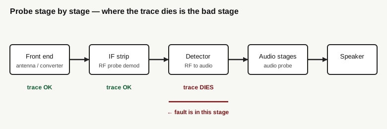
A radio or television receiver is a chain of stages, each handing a processed version of the signal to the next: antenna and front-end converter, an intermediate-frequency (IF) strip, a detector that recovers the audio, then one or more audio stages driving the speaker. When such a set goes dead or weak, the fault is almost always somewhere in that chain — one stage has stopped passing signal, and every stage downstream of it is starved as a result.
Two complementary techniques localize that fault fast:
- Signal injection feeds a known test signal into the chain at successive points and listens at the set’s own speaker for it to come through. You inject, and the set is the indicator.
- Signal tracing does the mirror image. You leave the set running on a real (or externally supplied) signal and carry a portable amplifier-plus-indicator through the chain, probing point by point, listening and watching for the signal to still be present. You are the mobile indicator; the set under test is left as-is.
The Z-80 is a pure tracer. You move its probe from stage to stage. As long as you hear the program material on the Z-80’s speaker (and see the magic eye respond), the signal is alive up to that point. The moment you step to a probe point where the trace goes silent and the eye goes dark, you have bracketed the fault: it lies between the last good point and the first dead one. That is the entire diagnostic loop, and it is remarkably quick — often minutes to isolate a fault that would take far longer to chase by measuring DC voltages against a schematic.
1.2.1 Why “tracer,” emphatically not “generator” or “injector”
It bears repeating because it governs how you use the instrument and because catalog shorthand and casual descriptions blur the line constantly: the Z-80 generates nothing. It has no oscillator, no marker source, no tone injector, no built-in test-signal output of any kind. If a stage is dead and you want to know whether the stages downstream of it are healthy, the Z-80 alone cannot help — you would need a signal source to inject after the dead stage. That source is a different tool. In the PACO catalog it is the G-30 / G-34 generator series (RF and TV-FM marker generators). The Z-80 and a G-series generator are natural bench partners — tracer plus injector — but they are two separate boxes doing two opposite jobs. Anyone who tells you the Z-80 “injects a signal on some models” is describing a machine that does not exist.
1.3 What the Z-80 specifically is
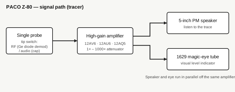
Reduced to a block sketch, the Z-80 is:
probe → high-gain amplifier (with a 1× to 1000× step attenuator) → 5-inch permanent-magnet speaker AND a 1629 magic-eye indicator tube, in parallel.
A few specifics that distinguish it from the generic idea of “a tracer”:
- A single switched probe. The factory Z-80 shipped with one probe carrying a tip switch. In its RF position the probe demodulates — a germanium crystal rectifier (diode) in the probe recovers the audio envelope off an RF or IF carrier — so the amplifier downstream only ever sees audio. In its audio position the probe is essentially a blocking capacitor that passes audio-frequency signal straight through. One probe, both jobs, selected at the tip. (Because original probes are frequently missing or incomplete on surviving units, owners commonly substitute a two-piece set — one RF/demodulator probe with the diode, one audio probe with a cap — but that is an owner workaround, not the factory configuration.)
- A magic eye, not a meter. The Z-80’s visual indicator is a 1629 electron-ray “magic-eye” tube — the glowing wedge whose shadow angle closes up as signal level rises. There is no moving-coil (D’Arsonval) panel meter on this instrument. When older notes call it a “meter,” they mean the eye. The eye is a relative level indicator you read alongside your ears, not a calibrated voltmeter.
- A speaker you actually listen on. The signal is presented audibly on a built-in 5-inch permanent-magnet dynamic speaker, in parallel with the eye. In practice you use both senses at once: the ear tells you what the signal is (program audio, hum, hiss, distortion, nothing), the eye tells you how much of it there is.
- A wide-range attenuator. The internal amplifier is high-gain, fronted by a 1× to 1000× range attenuator, so it can handle everything from a whisper of signal at a high-impedance grid to a robust level at a speaker terminal without overloading.
Beyond straight tracing, the Z-80 carries a few service extras that come up again in later volumes: output-transformer and speaker substitution terminals (bring the set’s audio out to the Z-80’s own transformer and speaker to prove out a suspect output transformer or speaker), an AC wattmeter load outlet (plug the set under test into it to read its AC power draw), and general amplifier-input testing of phono pickups, microphones, and tuners. None of those are generation either — they are substitution and measurement functions.
1.4 Where it came from: PACO and Precision Apparatus
PACO was not a standalone company in the ordinary sense — it was the kit-line brand of the Precision Apparatus Company, a long-established American test-equipment maker. PACO Electronics Co. operated as a division of Precision Apparatus, and the Z-80’s own nameplate says exactly that: “PACO Electronics Co., Glendale, L.I., N.Y., a division of Precision Apparatus.” The address on record is 70-31 84th Street, Glendale 27, Long Island, New York.
The corporate lineage runs Precision Apparatus Co. → the PACO division → later Pacotronics → eventually a division of Dynascan Corp. PACO’s stock-in-trade was affordable test gear and hi-fi, sold in both kit and factory-assembled form — a smaller player alongside the era’s better-known kit names, but a real one with a full catalog: signal tracers (the “Z” series), the G-30 / G-34 signal generators, the 660 / 910 / T-6x tube testers, the V-70 VTVM, the S-50 / S-55 oscilloscopes.
Dates. The Z-80’s Assembly and Operating Manual is dated 1957; catalog references put the build year around 1960. That places the instrument squarely in the late-1950s-to-early-1960s kit era — the golden age of the home-service and hobbyist test bench, when a technician or a serious amateur could buy capable instruments as a bag of parts and a manual and wire them up over a few evenings.
Kit or factory-wired. The Z-80 was sold both ways: as a kit to assemble and as a factory-wired unit. The kit was the more common, catalogued form (PACO’s whole reason for being was the kit price point), but a wired version existed for buyers who wanted it built.
1.4.1 One naming caution
“Z-80” here is purely a PACO model number. It has nothing to do with the Zilog Z80 microprocessor, which did not exist until 1976 — nearly two decades after this manual. The overlap is a coincidence of alphanumerics. In PACO’s scheme the “Z” prefix designates the signal-tracer series; this is simply the Z-80 tracer.
1.5 The core method in practice
The workflow the instrument is built around is the same every time, and it is the reason a tracer is such a fast diagnostic:
- Power the set under test and give it a signal. Either it is receiving a live station, or you feed it a known signal from a separate generator (a PACO G-30 or any RF/marker source). The set must be running — tracing is a live-circuit technique.
- Probe from the front end toward the speaker. Start at the antenna/converter, work through the IF strip, then the detector, then the audio stages. In the RF and IF sections the probe’s RF position demodulates the carrier so you hear the recovered audio; past the detector you switch to the audio position.
- At each point, listen and watch. Signal present on the speaker and a responsive magic eye means everything up to that point is passing signal.
- Find where it dies. The first probe point at which the trace goes silent — where the stage before it was alive and this one is not — brackets the fault. The bad stage is the one between the last good point and the first dead one.
That is the “where the trace dies is the bad stage” method in full. It localizes to a stage in one pass down the chain. From there the ordinary stage-level work begins — checking the tube, the coupling caps, the resistors, the alignment — but you have already spent your diagnostic time where it counts, on the one stage that matters, instead of measuring every node in the set.
The Z-80’s range of service targets follows directly: aligning and troubleshooting AM and FM radios and TV (IF, video/detector, and audio sections), plus checking speakers, output transformers, phono pickups, microphones, and tuners through the substitution terminals and the amplifier input.
1.6 Why it earns bench space
Jeff owns one, and it lives on a bench that also carries modern instruments. The reasons a 1957 tracer is not a shelf ornament:
- It matches the era of the work. This bench restores tube-era radios and TVs. A tracer is the fastest way into a dead tube-set signal chain, and the Z-80 speaks that circuitry natively — high-impedance probing, RF demodulation, audio, all in one box tuned to the voltages and levels of the gear it was built to service. You are diagnosing 1950s-1960s receivers with a 1950s-1960s instrument that was designed for exactly them.
- The method beats brute force. For a signal-path fault — the most common failure in a receiver that powers up but is dead, weak, or distorted — tracing localizes to a stage in minutes. Chasing the same fault by measuring DC operating voltages node-by-node against a schematic is far slower.
- Ear plus eye is a genuinely good interface. The speaker tells you the character of the trouble — hum, hiss, distortion, motorboating, silence — which a bare number never will; the magic eye gives you the relative level at a glance. Together they read faster than a meter for this job.
- The extras are useful. Speaker and output-transformer substitution lets you prove a suspect transducer or transformer in seconds by swapping the Z-80’s own known-good parts in; the wattmeter outlet gives a quick read on a set’s power draw. These fold naturally into a restoration session.
- It is serviceable and knowable. Five tubes, a handful of stages, a probe, a speaker, an eye. Nothing about it is a black box. It is exactly the kind of instrument this project exists to understand, restore, and keep running — and, being tube-era, it is itself a candidate for the same recap-and-restore discipline covered in Vol 5.
The counterweight, stated plainly so the frame is honest: the Z-80 is a tracer only. A complete tube-era service bench pairs it with a signal source (the injector/generator side — Vol 2 draws that line and places the Z-80 against its EICO and Heathkit contemporaries), and any live-chassis work on the AC-DC “hot chassis” sets of the era demands isolation-transformer discipline (Vol 5). Used for what it is, though, it remains one of the quickest paths into a dead vintage receiver.
1.7 How this dive is organized
This is Volume 1 of six. The rest:
- Vol 2 — Signal tracing and where the Z-80 fits. The tracer-vs-injector/generator distinction in full (and why the generator is PACO’s separate G-30 / G-34, not this box); the tube-era radio/TV service bench; how the Z-80 stacks up against the EICO and Heathkit tracers of the day.
- Vol 3 — Hardware and circuit. The single switched RF/audio probe and its germanium demodulator; the high-gain amplifier and 1×-1000× attenuator; the parallel speaker and 1629 eye; the five tubes (12AV6, 12AU6, 12AQ5, 12X4 rectifier, 1629 magic eye); 117 V AC mains; and the substitution and wattmeter functions in detail.
- Vol 4 — Operating it. Tracing a dead AM/FM radio or TV chassis stage by stage; reading the eye and listening on the speaker together; using the substitution outputs to swap a suspect speaker or output transformer; the wattmeter.
- Vol 5 — Refurbishing. Tube-era restoration — recapping wax and electrolytic caps, the aging 1629 eye, probe and cable repair, and the safety discipline for 117 V mains and hot-chassis AC-DC sets under test.
- Vol 6 — Cheatsheet and context. Quick-reference tables (tube complement, functions), where the Z-80 sits versus signal generators and injectors and modern approaches, and owner figure slots for Jeff’s unit.