PACO Z-80 Audio-RF Signal Tracer · Volume 2
PACO Z-80 — Vol 2: Signal Tracing & Where the Z-80 Fits
Tracer vs injector, the tube-era service bench, and PACO’s kit line
2.1 The one distinction that defines this instrument
Everything the Z-80 is — and everything it is not — comes down to which way the signal moves through the chassis on the bench.
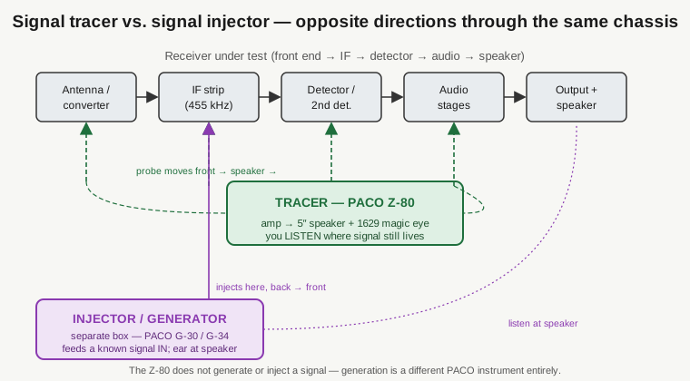
A signal tracer is a portable, self-contained amplifier with its own indicator. You carry its probe into a live circuit and ask, at each point, “is the signal still here?” The Z-80 takes whatever it finds at the probe tip, runs it through a high-gain internal amplifier with a 1×–1000× step attenuator, and presents the result two ways at once: audibly on a 5-inch permanent-magnet dynamic speaker, and visually on a 1629 magic-eye tube. Nothing about that chain originates a signal. The Z-80 is a listening post you can plant anywhere in a working receiver.
A signal injector (or, when it produces a calibrated, tunable output, a signal generator) is the mirror image. It originates a known signal and feeds it into the circuit at a chosen stage, while you listen at the far end — usually the receiver’s own speaker. Where the injected tone stops coming out the back is the clue.
These are dual techniques, and the two together localize almost any signal-path fault in a tube receiver in minutes. But they are opposite operations performed by different boxes. The Z-80 is squarely, and only, the tracer half.
2.1.1 Why this matters enough to hammer on it
The Z-80’s own front panel invites the confusion. It has an internal amplifier, a speaker, output-transformer terminals, and an AC power outlet — the same furniture you’d find on a small generator or an amplifier-in-a-box. It is tempting to read “audio output transformer connections” and picture the Z-80 driving a tone into the radio under test. It does not.
The catalog feature list for the Z-80 is explicit and finite: 1× to 1000× range attenuator, internal speaker, transformer connections, AC wattmeter, magic-eye. There is no oscillator, no marker, no modulated RF, no audio tone source anywhere in the design. When the manual and the catalogs list the functions — signal tracing in the RF and audio sections, noise testing, speaker-substitution testing, speaker verification, and microphone/pickup/tuner testing — every one of them is an act of receiving and amplifying something that already exists, or of substituting a known-good component. None of them is signal generation.
If you need to inject, that job belongs to a different instrument on the bench (Section 3), and in PACO’s own catalog it belonged to a different product line entirely (Section 4).
2.2 What “tracing stage by stage” actually looks like
The method the Z-80 is built for is simple enough to state in one sentence and powerful enough to have defined a service era: with the receiver powered and receiving — either off the air or fed a signal from a separate generator — you probe from the front end toward the speaker, one stage at a time, and where the trace dies is the bad stage.
Concretely, on an AM broadcast set the path runs antenna/converter → IF strip (at the conventional AM-broadcast IF, typically 455 kHz — a property of the receiver, not of the Z-80) → detector → audio voltage amplifier → audio output → speaker. You start at or near the front and walk the probe downstream:
- In the RF and IF sections, the signal is a modulated carrier the ear can’t use directly. Here the probe’s germanium crystal rectifier demodulates it — strips off the carrier and hands the recovered audio envelope to the Z-80’s amplifier. You hear the station’s program material and watch the magic eye close on modulation peaks.
- At the detector and beyond, the signal is already audio. The probe’s audio position passes it straight through a blocking capacitor to the amplifier, no demodulation needed.
- At every tap, the magic eye gives you a relative level and the speaker gives you the character of the signal — clean program, hum, hash, distortion, or dead silence.
The diagnosis is differential, not absolute. You are not reading a calibrated voltage; you are comparing “signal present and healthy” against “signal gone or degraded” as you step through the chain. The stage before the point where the trace vanishes is working; the stage across which it disappears is the fault. That is faster than chasing DC voltages against a schematic node by node, because you follow the actual signal instead of inferring it.
The reason a single instrument can do this from antenna to speaker is that the Z-80 carries both front ends into one probe. The RF position gives you a detector so the IF and RF stages become audible; the audio position gives you a flat, direct path for everything past the detector. Vol 3 covers that switched probe and the amplifier behind it in circuit detail; Vol 4 walks a real dead-chassis trace end to end.
2.2.1 The factory probe: one switch, both jobs
It is worth being precise here because owners’ setups vary. The factory Z-80 shipped with a single probe carrying a tip switch that swaps the demodulator element in and out, so the one probe serves both RF/IF (crystal-rectifier demodulation) and audio (straight-through) work. Because original probes are frequently missing or damaged after sixty-odd years, owners commonly rebuild to a two-probe set — one RF/demodulator probe with the germanium diode, one audio probe with just a blocking capacitor. That two-piece arrangement is a practical substitution, not the original configuration. Functionally the two are equivalent; the factory simply put both modes under one thumb.
2.3 The tube-era service bench, and the four questions
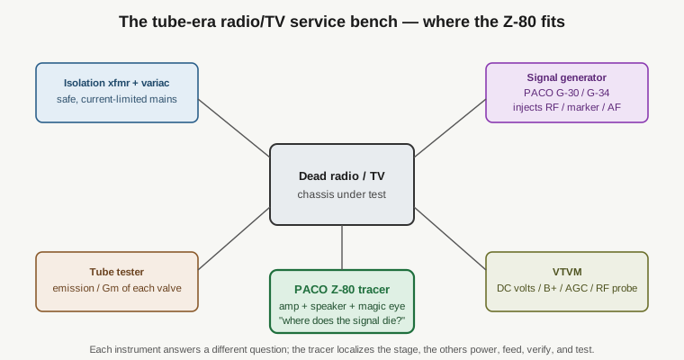
The Z-80 never worked alone. A postwar radio/TV service bench was a small constellation of single-purpose instruments, each answering one question about a dead set. Understanding the neighbors is the fastest way to understand what the tracer is for — and what it deliberately leaves to others.
The four questions, and who answers them:
- “Is it getting safe power?” — the isolation transformer and variac. Most of these radios are transformerless AC/DC “hot chassis” designs; you bring them up slowly on a variac through an isolation transformer, never straight off the wall. (The Z-80 itself runs from 117 V AC mains and includes an AC wattmeter outlet so you can read how much the set under test is drawing — a power-consumption check, not a power source.)
- “Are the tubes good?” — the tube tester (in Jeff’s stable, the Heathkit TT-1 and the Supreme 385). It grades emission or transconductance valve by valve. A weak tube and a bad coupling cap can present identically to a tracer, so the tube tester rules out the tubes first.
- “Are the DC operating points right?” — the VTVM. B+, screen and plate voltages, AGC/AVC bias, and — with an RF probe — signal amplitudes are its department. The VTVM tells you the stage is biased to work.
- “Where does the signal actually stop?” — the signal tracer. This is the Z-80’s question, and only the Z-80’s. It doesn’t measure voltage, grade tubes, or supply power; it follows the audio/RF signal and tells you which stage killed it.
A generator sits in that constellation too, and it’s the instrument most often confused with the tracer, so it gets its own treatment below.
2.3.1 Tracer and generator are partners, not substitutes
On a completely dead set — one that isn’t receiving anything off the air — the tracer has nothing to follow. That is exactly when you reach for a generator: feed a known modulated RF signal into the antenna or a chosen stage, then trace it downstream with the Z-80. The generator supplies the signal; the tracer finds where it disappears. They are complementary halves of one workflow, which is precisely why it’s a mistake to expect one box to do both. The Z-80 assumes a signal exists — from the air or from a generator — and its whole job is to tell you where that signal lives and dies.
The Z-80’s amplifier input also does useful non-tracing duty in the same “listen to what’s really there” spirit: feed it a phono pickup, a microphone, or a tuner output and it becomes a test amplifier to prove those sources are alive. Again — amplifying an existing signal, never making one.
2.4 PACO, the kit line, and where the generator lives
The Z-80 came from PACO Electronics Co., the kit/lower-cost brand line of the Precision Apparatus Company, offered both as a kit and factory-wired in the late-1950s-to-early-1960s (manual dated 1957, catalogued around 1960). Vol 1 gives the full treatment — the Precision Apparatus → PACO division → Pacotronics → Dynascan lineage, the nameplate wording, and the naming caution that this “Z-80” long predates and has nothing to do with the Zilog Z80 microprocessor. What matters here is a narrower point about PACO’s catalog: where the signal-generation function actually lives.
Crucially, PACO’s catalog was a family of single-purpose instruments, and that family is where the “does it generate a signal?” question gets its cleanest answer: it doesn’t, because PACO built a separate product for that. The signal-generation function the Z-80 is sometimes wrongly credited with lived in PACO’s G-series — the G-30 / G-30PC / G-34 RF signal and TV-FM marker generators, covering roughly 160 kHz to 240 MHz. Those are the injectors; the Z-80 is the tracer. The two were meant to sit side by side on the bench, not to be one instrument.
For orientation, the rest of PACO’s line around the Z-80 sorted the same way — one box, one job:
Table 1 — For orientation, the rest of PACO's line around the Z-80 sorted the same way — one box, one job
| PACO model(s) | Class | What it does |
|---|---|---|
| Z-80 | Signal tracer | Audio + RF tracing; the instrument of this dive |
| G-30 / G-30PC / G-34 | Signal / marker generators | Originate RF and TV-FM marker signals (~160 kHz–240 MHz) |
| 660 / 910 / T-60 / T-61 / T-62 / T-63 | Tube testers | Grade emission / transconductance |
| V-70 | VTVM | High-input-impedance voltage measurement |
| S-50 / S-55 | Oscilloscopes | Waveform display |
The takeaway from the table is the same as the takeaway from the bench: PACO expected you to own several of these, each doing one thing well. The Z-80 traces. If you wanted to inject, you bought a G-30.
2.4.1 How the Z-80 compares to EICO and Heathkit tracers
In the budget-kit signal-tracer market, PACO’s principal rivals were EICO and Heathkit, and the Z-80 sat toward the more-featured end of that field. The comparison worth drawing is not one of raw performance — these are all modest tube amplifiers with a probe — but of how the result is presented and what extras ride along.
- The indicator. Many contemporary tracers relied on the ear alone or on a small moving-coil meter for a relative-level read. The Z-80 uses a 1629 magic-eye (electron-ray) tube as its visual level indicator — the shadow angle closes as signal rises — in parallel with the speaker. You get eyes and ears at once. This is also the single most-corrected fact about the Z-80: it has no D’Arsonval panel meter; the “indicator” everyone means is the magic eye. The 1629 is a wartime-surplus staple with a 12.6 V / 150 mA heater and an octal base, which is why it drops neatly into a chassis whose other tubes are already 12-volt types.
- The bundled extras. Beyond tracing, the Z-80 folds in an output-transformer / speaker substitution function (terminals expose the set’s own center-tapped audio output transformer and speaker so they can stand in for a suspect transformer or speaker in the radio under test) and an AC wattmeter load outlet (plug the set under test into it to read its AC power draw). Both are diagnostic conveniences that save reaching for another instrument — but note neither is a signal source. The substitution terminals can carry full B+ (on the order of 270 V), so they are handled with the same respect as any live plate circuit.
- What it pointedly lacks. No built-in generator, no injector, no marker. That omission is deliberate and consistent with the whole PACO catalog philosophy: generation is the G-series’ job.
Set against an EICO or Heathkit tracer of the same years, then, the Z-80’s personality is “tracer plus a couple of bench-saving extras, read out on a magic eye.” It is not trying to be a signal source, and reading it as one — the recurring error this instrument attracts — misses both what it is and how PACO intended it to be used.
2.5 Where this leaves us
The Z-80 is a signal tracer: a probe, a high-gain amplifier with a 1×–1000× attenuator, and a dual speaker-plus-magic-eye indicator, built to be carried stage by stage through a live receiver until the trace dies at the bad stage. It powers nothing into the circuit and generates no signal of its own — that is the G-30/G-34’s job, on a different part of the bench. It came from PACO, the kit line of Precision Apparatus, as a 1957/~1960 kit or factory-wired unit, with speaker-substitution terminals and an AC wattmeter folded in as diagnostic extras.
Vol 3 opens the case: the switched RF/audio probe and its germanium demodulator, the five-tube complement — a three-stage amplifier (12AV6, 12AU6, 12AQ5) plus the 12X4 rectifier and 1629 magic eye — the parallel speaker-and-eye output, and the substitution and wattmeter circuitry. Vol 4 puts a probe in hand and traces a dead AM/FM/TV chassis end to end.