PACO Z-80 Audio-RF Signal Tracer · Volume 3
PACO Z-80 — Vol 3: Hardware & Circuit
The switched probe, the high-gain amp, the 5″ speaker and the 1629 magic eye
3.1 The whole box in one sketch
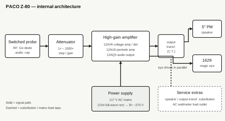
Strip the Z-80 to its signal path and it is short enough to hold in your head:
probe → 1×–1000× attenuator → high-gain amplifier → 5-inch permanent-magnet speaker AND a 1629 magic-eye tube, in parallel.
Everything else on the chassis is either the power supply that feeds that chain or a service extra hung off it — the speaker/output-transformer substitution terminals and the AC wattmeter load outlet. Five tubes do the work: a 12AV6, a 12AU6, a 12AQ5, a 12X4 rectifier, and the 1629 magic eye. One germanium crystal diode lives out in the probe. The set runs from 117 V AC mains.
None of this generates a signal. There is no oscillator, no marker source, no injector anywhere in the box. The Z-80 is an amplifier with an ear and an eye on its output; the probe is how you tap the circuit under test, and the two indicators are how you read what the probe found. This volume walks that chain from the probe tip to the speaker cone and back to the mains cord.
3.2 The switched probe
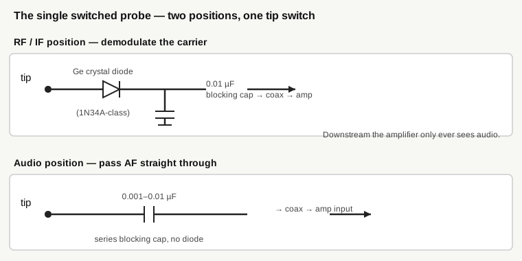
The probe is the front door, and on the factory Z-80 it is a single probe with a tip switch. That one detail is worth getting right, because it governs everything downstream: the amplifier inside the box is an audio amplifier and only an audio amplifier. It never sees RF. The job of turning an RF or IF carrier into something the audio amplifier can handle is done out at the probe tip, before the signal ever travels down the cable.
The tip switch selects between two configurations of the same probe.
3.2.1 RF / IF position — demodulation at the tip
In its RF position the probe is a crystal-diode demodulator. A germanium crystal rectifier — the PACO manual calls for exactly that, a “crystal rectifier,” the part a modern rebuild fills with a 1N34A / 1N48 / 1N60 / 1N270-class germanium diode — rectifies the modulated carrier and a small blocking capacitor (on the order of 0.01 µF) strips the RF, leaving the recovered audio envelope. That envelope is what runs down the cable to the amplifier.
This is the same envelope-detector trick the receiver’s own detector stage performs, done in miniature in the probe so that you can listen to modulation anywhere upstream of the set’s detector — at the antenna and converter, all through the IF strip — and hear the program material the carrier is carrying. Germanium is the right device for it: its low forward drop (a few tenths of a volt, against ~0.6 V for silicon) rectifies the small RF and IF signals you are probing where a silicon diode would barely conduct. The probe is a passive demodulator — it needs no power of its own — and it is the reason a plain audio amplifier can trace an RF chain at all.
3.2.2 Audio position — a blocking cap and nothing else
Flip the tip switch to the audio position and the diode drops out. What is left is essentially a series blocking capacitor (roughly 0.001–0.01 µF) and a straight path to the amplifier. The capacitor blocks the DC operating voltage present at whatever node you are touching — control grids, plates, coupling points all sit at some DC potential — while passing the audio riding on it. No rectification happens because none is wanted: past the set’s detector the signal is already audio, and you simply want to couple it into the tracer and listen.
So one probe, two jobs, chosen at the tip: demodulate an RF/IF carrier, or capacitively couple an existing audio signal. In both positions the amplifier downstream sees the same thing — audio.
3.2.3 The two-probe substitution owners run
Original probes are frequently missing, broken, or gutted on surviving Z-80s — the cables perish, the tip switch corrodes, the diode gets lost. A very common owner fix is to give up on the single switchable probe and run a two-piece set instead: one dedicated RF/demodulator probe carrying the germanium diode and its blocking cap, and one dedicated audio probe carrying just a coupling capacitor. Functionally it is identical — you swap probes instead of flipping a switch — but it is worth stating plainly that this is the owner workaround, not the factory configuration. The Z-80 left the factory with one switched probe.
3.3 The attenuator: 1× to 1000×
Between the probe input and the amplifier proper sits the range control: a 1× to 1000× step attenuator. It exists because the levels you probe span an enormous range. At a high-impedance control grid deep in the front end you may be chasing microvolts of recovered audio; at a speaker or output-transformer terminal you have volts. A single fixed-gain amplifier cannot serve both — it would be deaf at one end and slammed into gross overload (and a blown-open, useless indication) at the other.
The 1×–1000× span is three decades of range. At 1× the full amplifier gain is available for the faintest traces up near the antenna; at 1000× the input is knocked down by a factor of a thousand so a robust signal at the back end of the set drives the eye and speaker to a sensible level instead of pinning them. In practice you set the attenuator for a comfortable indication at each probe point and read changes as you step through the stages — the attenuator is what lets a single instrument stay on-scale across the whole receiver.
3.4 The high-gain amplifier and its tubes
Everything past the attenuator is a conventional tube audio amplifier — the same architecture as the audio section of a table radio of the period, which is exactly the point: it is built to reproduce, cleanly and loudly enough to judge, the audio the probe hands it. Three tubes carry the signal.
3.4.1 12AV6 — input voltage amplifier / detector
The 12AV6 is a twin-diode / high-mu triode — the classic detector-and-first-audio tube from millions of AM radios. In the Z-80 it sits at the front of the amplifier as the high-gain input voltage-amplifier stage, taking the small signal from the probe and attenuator and bringing it up. Its diodes and high-mu triode are the same elements that did detection and first-audio duty in the very receivers the Z-80 is built to service, so the tube is entirely at home amplifying a weak recovered-audio signal to a usable level.
3.4.2 12AU6 — pentode voltage amplifier
The 12AU6 is a sharp-cutoff pentode running as the next voltage-amplifier stage, adding the gain needed to drive the output tube hard from a small input. A pentode here gives high gain per stage with good isolation between input and output; cascaded after the 12AV6 it is what makes the amplifier genuinely high-gain — sensitive enough to hear microvolt-level traces up in the front end when the attenuator is wide open at 1×.
3.4.3 12AQ5 — audio output pentode
The 12AQ5 is a beam-power / audio-output pentode — a miniature 7-pin relative of the 6V6 family — and it is the tube that actually drives the speaker. It takes the amplified audio from the voltage-amp stages and delivers the power to move a 5-inch cone at a listenable volume through the output transformer. It is the one tube in the signal chain running real plate current into a load rather than just developing voltage gain.
The chain, then, is 12AV6 (voltage amp / detector) → 12AU6 (pentode voltage amp) → 12AQ5 (audio output) → output transformer → speaker, with the 1629 eye taken in parallel off that output. Three signal tubes, a plain and serviceable topology, nothing exotic.
3.5 The output: speaker and magic eye in parallel
The amplifier’s output does two things at once, and the “at once” matters.
3.5.1 The 5-inch speaker — the ear
The signal is presented audibly on a built-in 5-inch permanent-magnet dynamic speaker, driven through the output transformer off the 12AQ5. This is not a token beeper — it is a real speaker you listen on, and listening is half the instrument. The ear reports the character of the trace in a way no meter ever will: clean program audio versus hum versus hiss versus distortion versus motorboating versus dead silence. When you are tracing a set that is “weak and distorted,” it is the speaker that tells you distorted, and where in the chain the distortion first appears. The PM (permanent-magnet) construction means no field-coil supply is needed — the magnet does the work — which keeps the speaker circuit simple and the whole box lighter (the Z-80 runs about 2.9 kg / 6 lb 7 oz in a roughly 295 × 195 × 150 mm case).
3.5.2 The 1629 magic eye — the eye
In parallel with the speaker, the output also drives the 1629 electron-ray “magic-eye” indicator tube — the visual level indicator, and emphatically not a moving-coil panel meter. There is no D’Arsonval movement anywhere on this instrument. The 1629 is a tuning-eye tube: a fluorescent target whose glowing wedge (its “shadow angle”) closes as the applied signal grows, so the eye opens and closes with the level of the trace. You watch the wedge, not a needle.
The 1629 itself is a specific and slightly unusual choice. Electrically it is close kin to the familiar 6E5 / 6U5 magic-eye tubes, but it carries a 12.6 V / 150 mA heater on an octal base rather than the 6.3 V, 6-pin arrangement of the common eyes. That 12.6 V heater is the tell: it matches the 12-volt heaters of every other tube in the box. The 1629 was a WWII-surplus staple — the VT-138, used as a tuning indicator in ARC-5 command sets — which made it cheap and plentiful in the postwar kit era, and it dropped straight into a 12.6 V heater string alongside the rest of the Z-80’s tubes without a separate winding. It is exactly the sort of pragmatic, surplus-friendly part choice that defined kit-era design.
Using both indicators together is the intended workflow: the eye gives you relative level at a glance — how much signal is present, and whether it grows or collapses as you step from stage to stage — while the ear tells you what that signal actually is. Neither alone is as fast as the two together, and neither is a calibrated measurement. The eye is a relative-level indicator, not a voltmeter; you read trends and presence, not volts.
3.6 Power: 117 V mains and the 12X4
The Z-80 runs from 117 V AC line (a 220 V option is noted). The fifth tube, the 12X4, is the full-wave rectifier that makes the B+ rail — the high-voltage DC that the amplifier tubes’ plates and screens run on. A 12X4 is a compact 7-pin full-wave rectifier with a 12.6 V heater, and its full-wave configuration works from a center-tapped high-voltage secondary to produce a B+ of roughly 270 V. That B+ figure is not incidental trivia — it shows up at the substitution terminals, and it is a shock hazard you handle deliberately (Vol 5 covers bleeding it down and the general mains/HV discipline).
Two things about the power design are worth pulling out. First, the heater lineup is deliberately coherent: every tube is a 12-volt type — 12AV6, 12AU6, 12AQ5, 12X4, and the 12.6 V 1629 — so they share one heater voltage rather than needing a mix of 6.3 V and 12.6 V windings. That is why the 12.6 V/octal 1629 was chosen over the more common 6.3 V eyes, and why the 12X4 was chosen over a 6.3 V rectifier like a 6X4: heater commonality. Second, the 12X4’s full-wave rectification and the presence of B+ out at the substitution terminals both point to a mains power transformer with a high-voltage secondary feeding the rectifier — a transformer-supplied set, not a raw line-connected “hot chassis.” (The hot-chassis caution in this project is about the AC-DC radios under test, not the Z-80 itself — see Vol 5.)
3.7 The service extras
Past the tracer proper, the Z-80 carries a handful of measurement and substitution functions that share the same speaker, transformer, and eye. None of them is signal generation. They are ways to use the audio output and the mains to test parts of a receiver directly.
3.7.1 Output-transformer and speaker substitution
The catalog line “transformer connections” refers to substitution terminals that bring the Z-80’s own center-tapped audio output transformer and its speaker out to binding posts. The idea is direct: when you suspect a receiver’s output transformer or speaker is the fault, you connect the set’s audio output stage to the Z-80’s transformer and speaker and listen. If the audio comes through clean on the Z-80’s known-good transducer, the set’s own transformer or speaker was the culprit; if it is still bad, the trouble is further upstream. It is proof-by-substitution using parts you already trust because they are inside the tracer.
One hazard to flag, because it is a real trap: these substitution terminals can carry the full B+ — on the order of 270 V — since a tube output stage’s transformer primary sits at the plate supply. They are not low-level speaker terminals in the modern sense. Treat them as live HV points when the set (or the Z-80) is powered.
3.7.2 The AC wattmeter outlet
The Z-80 also provides an AC wattmeter function in the form of a load outlet: you plug the receiver (or other device) under test into the Z-80’s outlet, and the instrument reads the AC power the device draws from the line. It is a quick sanity check on a set’s mains consumption — a shorted or badly loaded set pulls abnormal power, and an open one pulls none. What the exact readout mechanism is — whether the power is indicated on the magic eye, on a marked scale, or worked out from another reading — is not something I can pin down from the sources at hand, and I am not going to assert a mechanism the manual would settle. The function is documented and real; the specific way it presents the number is a detail to confirm against the manual before relying on it.
3.7.3 Noise and input testing
Finally, the amplifier front end is useful in its own right for checking phono pickups, microphones, and tuners — plug a source into the amplifier input and listen/watch as you would any trace. The catalog’s “noise testing” belongs in the same category: it is a diagnostic listening mode — tap or flex a suspect component and listen for the noise it makes through the tracer’s amplifier — not a noise generator. There is no injection source of any kind in the Z-80, noise or otherwise. If a description implies the box can inject noise into a circuit, that capability is not there; “noise testing” means listening for noise the circuit itself produces, amplified by the tracer.
3.8 Reading the whole thing as a circuit
Put end to end, the Z-80 is an honest, legible instrument with nothing hidden:
- The probe does the only frequency-domain work in the box — germanium-diode demodulation in the RF position, plain capacitive coupling in the audio position — so that everything inside the chassis can be a plain audio amplifier.
- The 1×–1000× attenuator keeps that amplifier on-scale from the microvolt front end to the volt-level back end.
- Three signal tubes — 12AV6 input voltage amp/detector, 12AU6 pentode voltage amp, 12AQ5 audio output — build the gain and drive the load.
- The output feeds two indicators in parallel: the 5-inch PM speaker for the character of the signal, the 1629 magic eye for its level. No meter movement exists; the eye is the “meter.”
- The 12X4 and the 117 V supply make the ~270 V B+ everything runs on, with a deliberately all-12-volt heater lineup that is why the octal 1629 and the 12X4 were chosen over their 6.3 V cousins.
- The substitution terminals and the wattmeter outlet reuse the transformer, speaker, and mains to test suspect transducers and power draw directly — substitution and measurement, never generation.
That is the complete hardware picture. Vol 4 puts it to work — probing a dead AM/FM or TV chassis stage by stage, reading the eye and the speaker together, and driving the substitution and wattmeter functions in a real service session.