PACO Z-80 Audio-RF Signal Tracer · Volume 4
PACO Z-80 — Vol 4: Operating It
Tracing a dead chassis stage by stage — magic eye, speaker, and substitution
4.1 The job the Z-80 actually does at the bench
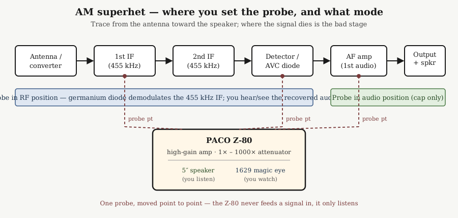
The Z-80 is a listening instrument. You move its single switched probe through a live receiver, point by point, and at every point you find out — by ear on the 5-inch speaker and by eye on the 1629 magic-eye tube — whether the signal is still alive there. It never puts a signal into the circuit. That distinction is the whole method: the chassis under test has to be doing its own work (receiving a station, or being driven by a separate generator such as PACO’s G-30), and the Z-80 simply reports where along the chain the signal is still present and where it has gone. Where the trace dies is the bad stage. Everything in this volume is a way of making that one sentence pay off faster.
Two things follow from that immediately. First, the receiver has to be powered and, ideally, actually receiving something — a strong local AM station tuned in is the cheapest test signal there is. Second, because you are working on a powered, often AC-DC “hot chassis” receiver while touching it with a grounded probe, the isolation-transformer discipline covered in Vol 5 is not optional; skimming it before your first trace is the right order of operations. This volume assumes the set under test is already on an isolation transformer and that you have read the safety material.
The signal path inside the Z-80 — probe → high-gain amplifier with a 1× to 1000× attenuator → speaker and magic eye in parallel — is the hardware covered in Vol 3. Here it is only the instrument you hold; the receiver on the bench is the patient.
4.2 Front-panel orientation before the first probe touch
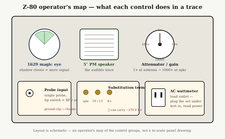
There are only a handful of things to set, and they map cleanly onto the trace.
4.2.1 The two indicators, read together
The 1629 magic-eye tube is the visual level indicator — an electron-ray “tuning eye,” electrically in the 6E5/6U5 family but with a 12.6 V / 150 mA heater on an octal base. Its shadow angle narrows as the signal driving the amplifier grows. You read it the way you read any magic eye: a wide-open shadow means little or no signal at the probe tip; a shadow that closes toward a thin wedge means a strong signal. It is not a calibrated meter — there is no moving-coil movement anywhere on this instrument — so treat it as a fast relative indicator. Its real value is that your eyes catch a change in the eye faster than your ears settle on a change in loudness, and it works on signals too weak or too distorted to be pleasant to listen to.
The 5-inch PM dynamic speaker is the audible half of the same output. This is where the character of the fault lives: a clean station, a hum, a rasp, intermittent crackle when you tap a stage, motorboating, or dead silence. The magic eye tells you how much; the speaker tells you what kind. In practice you keep one eye on the tube and listen the whole time, and you learn to trust the combination.
4.2.2 The attenuator is your altitude control
The 1× to 1000× step attenuator ahead of the high-gain amplifier is the single most important operating control. The signal you are chasing spans an enormous range as you walk the chain: microvolts of RF at the antenna and converter, tens of millivolts by the last IF, volts of audio at the output-tube grid, and speaker-level audio at the very end. If you leave the attenuator at high gain when you probe an audio stage you will overload the Z-80’s amplifier, slam the magic eye shut, and blast the speaker — telling you nothing except that there is a lot of signal there.
The working rule is: the closer you probe to the antenna, the more gain you want (toward 1×, i.e. no attenuation, full amplifier gain); the closer you probe to the speaker, the more you attenuate (toward 1000×). Set gain for a partly-closed magic eye and a comfortable listening level at each point, then compare stages at like settings. A stage that needs noticeably more gain than the one before it to reach the same eye deflection is telling you it is losing signal, even if it is not yet dead.
4.2.3 The single switched probe
The factory Z-80 ships with one probe carrying a tip switch, not a two-piece set. The switch selects between the two modes the trace needs:
- RF position — a germanium crystal diode (the manual’s “crystal rectifier,” a 1N34A-class part in modern rebuilds) demodulates the RF/IF signal at the tip, so what reaches the amplifier is the recovered audio — the demodulated envelope, with residual RF filtered off. This is the mode for everything from the antenna through the last IF and the detector input.
- Audio position — essentially a blocking capacitor with no diode, passing audio-frequency signals straight through. This is the mode from the detector output onward, through the audio stages to the speaker.
Because original probes are frequently missing, many owners substitute a two-probe set — one RF/demodulator probe, one audio probe — and simply swap probes where the factory unit would flip the tip switch. The procedure is identical either way; only the hardware in your hand differs. The probe’s ground clip goes to the receiver chassis (its actual signal ground — again, mind the hot-chassis warning), and it stays there for the whole trace.
4.3 The core procedure: tracing a dead AM chassis
This is the bread-and-butter use and the one every other trace is a variation on. Assume a table-radio superhet that powers up but is silent, hissing, or badly distorted.
4.3.1 Establish a signal to chase
Tune the receiver to a strong local AM station (or, if the front end is suspect and can’t pull one in, feed a modulated RF signal into the antenna from a separate generator — the Z-80 does not generate anything). You want a known-good, steady signal present at the antenna so that the only variable as you move down the chain is the receiver’s own stages.
4.3.2 Walk the chain front-to-back
Set the probe to RF and the attenuator near minimum attenuation (high gain), and start at the front and move toward the speaker:
- Antenna / converter (mixer) output. Probe the signal side of the converter. On a working set you should hear the station — weak, because you are early in the chain and the Z-80’s diode-demodulated RF is low-level — and see the magic eye react. Bring the gain up as needed.
- First IF (typically 455 kHz). Probe the plate/output of the first IF stage. The station should be noticeably louder / the eye more closed than at the converter, because the IF stage added gain. That increase is the point: each good stage should hand you a bigger signal than the one before.
- Second IF (455 kHz). Same again — louder still. You are watching the signal grow stage by stage.
- Detector. Probe the detector’s input (RF side, still in RF mode) and then its output (audio side — switch the probe to audio here). At the detector the signal changes character from “demodulated-in-the-probe” to “already-audio-in-the-circuit.”
- First audio (AF) amplifier. In audio mode, probe the AF amplifier’s grid and plate. Big jump in level — back the attenuator off toward 100× or more.
- Output stage and speaker. By the output-tube grid and the primary of the output transformer you are at the strongest audio in the set; attenuate hard (toward 1000×). The Z-80’s own speaker should be reproducing the station loudly and cleanly.
4.3.3 Read where it dies
The fault announces itself as the place where the pattern breaks:
- Signal present, then gone between two adjacent probe points → the stage between them is the suspect. Present at the first IF, absent at the second IF plate → the second IF stage (tube, its plate/screen supply, a coupling cap, an open IF transformer winding) is where to dig.
- Signal present all the way but never grows → a stage that passes signal without amplifying it (a weak or starved tube, a bad bypass, a wrong operating point). The magic eye is what catches this: equal deflection at like gain across a stage that should have added 20–30 dB is a stage doing no work.
- Signal present and clean up to a point, then distorted / hum-laden / intermittent past it → the character on the speaker localizes it. Hum riding in from one stage on tells you where a filter or cathode bypass has failed; a rasp that starts at one stage points at that stage’s coupling. Tapping components while you listen (the “noise testing” use — a diagnostic, not an injected signal) flushes out intermittents: an intermittent that crackles on the speaker only when you tap C or the tube at one stage has found itself.
Two or three stage jumps usually bracket the fault to a single stage in under a minute — far faster than DC-voltage-charting the whole chassis against the schematic.
4.4 FM and TV chassis — the same method, a few cautions
The stage-by-stage logic is unchanged for FM and TV; what differs is frequency and what the demodulated result sounds like.
- FM front ends and IF (10.7 MHz) run far above the AM IF. The germanium-diode RF probe will still show you presence of signal as you walk the FM IF strip — the eye reacts and you get an indication that RF is getting through each stage — but an envelope-detecting diode does not recover FM audio the way a proper discriminator/ratio detector does, so do not expect clean program audio out of the RF probe on the FM IF. Use the tracer there as a presence/level indicator stage to stage, and switch to the audio probe past the FM detector, where the recovered audio behaves exactly like the AM audio chain above.
- TV chassis are the same drill on multiple chains: the sound IF and audio stages trace exactly like a radio (find where the sound dies), and the tracer is genuinely useful on the audio side of a TV. The video/sync side is a scope job, not a signal-tracer job; keep the Z-80 to the RF-presence and audio roles it is built for. And a TV chassis is a high-voltage environment well beyond the radio cautions — Vol 5’s HV discipline governs.
Across all of it the attenuator habit is the same: high gain up front, attenuate as you approach the audio output.
4.5 Substitution: swapping in the Z-80’s own speaker and transformer
Beyond tracing, the Z-80 carries speaker / output-transformer substitution terminals — the catalog’s “transformer connections.” These expose the Z-80’s own audio output transformer (center-tapped) and its 5-inch speaker so they can stand in for a suspect one in the set under test.
The use is direct. If your trace reaches the output-tube grid with clean, strong audio but the receiver’s own speaker is silent or buzzy, the fault is downstream of that grid: the output transformer or the speaker itself. Rather than guess, substitute:
- Suspect speaker. Disconnect the receiver’s speaker (its voice coil) and bring the output-transformer secondary out to the Z-80’s speaker-substitution terminals so the Z-80’s known-good 5-inch speaker carries the set’s audio. If it now plays cleanly, the original speaker (open voice coil, rubbed/torn cone, fouled gap) was the fault.
- Suspect output transformer. Bring the output-tube plate and B+ to the transformer-substitution terminals so the Z-80’s known-good center-tapped output transformer (and its speaker) replace the set’s output transformer. Restored audio condemns the original transformer (open primary is the classic failure).
Two operating cautions that are easy to forget in the moment:
- These terminals can carry the set’s full B+ — on the order of 270 V. The transformer primary and the plate connection are at plate potential. Treat the substitution terminals as live HV: connect with the set off and B+ bled, observe the one-hand rule, and route the leads so they can’t flop onto you or the chassis. This is not a low-voltage speaker jack.
- Match the load sensibly. The substitution is meant to prove a stage good or bad, not to run the set indefinitely into a mismatched impedance. Make the swap, confirm the verdict, power down.
Substitution turns “the audio is dead past the output tube” from a two-part guess into two clean one-part tests.
4.6 The AC wattmeter outlet
The Z-80 also provides an AC wattmeter function as a load outlet: you plug the receiver (or other appliance) under test into the Z-80’s outlet, and the Z-80 reads the AC power the set is drawing from the 117 V line. In service, real-time power draw is a fast, non-invasive health check on the whole chassis before you ever pull the back off:
- A set drawing far more than its rated power points at a shorted filter capacitor, a shorted power transformer, or a shorted output tube pulling excess current — the classic “why is the transformer getting hot” case, caught in seconds.
- A set drawing far less than rated, or nothing, points at an open in the primary/heater string — a dead power transformer primary, an open fuse or line cord, or (in an AC-DC set) an open heater chain.
- Watching the draw as the set warms up distinguishes a healthy inrush-then-settle from a draw that climbs and keeps climbing (a leaky filter cap heating and drawing more) — the latter is a “shut it off now” signal.
The exact readout mechanism on this outlet isn’t documented in detail; read it against the set’s nameplate wattage and use it as a comparative, go/no-go power check rather than a precision power measurement. As a first-touch triage on an unknown chassis — before signal tracing even begins — it is genuinely useful: it tells you whether it is safe to leave the set powered while you probe.
4.7 Putting a session together
A typical dead-radio session on the Z-80 runs in this order:
- Wattmeter triage. Plug the set into the Z-80’s outlet, power up, watch the draw. Grossly wrong power → find the short/open before probing. Sane power → proceed.
- Establish a signal. Strong local AM station, or a generator into the antenna.
- RF trace, front to back. Probe in RF mode, high gain, walk converter → IF → detector, watching the eye grow stage to stage and listening for where it dies or degrades.
- Audio trace. Switch to audio mode past the detector, attenuate progressively, walk the AF and output stages.
- Substitution, if the trace reaches the output grid clean but the set is still silent. Swap the Z-80’s speaker and/or output transformer to split “bad transformer” from “bad speaker.” Mind the ~270 V.
- Localize and hand off. You now have a single suspect stage (or a specific speaker/transformer); the actual component-level repair — recapping, tube swap, transformer replacement — is Vol 5 territory.
The instrument’s contribution is entirely in steps 1 and 3–5: it makes an invisible signal audible and visible at any point you choose, and it lets you borrow a known-good speaker and transformer on the spot. It does not generate, it does not inject, and it does not measure to a calibrated scale. Used inside those honest limits — front-to-back, gain managed, eye and ear read together — it brackets almost any signal-path fault in a tube receiver faster than any other single tool on the bench.