PACO Z-80 Audio-RF Signal Tracer · Volume 5
PACO Z-80 — Vol 5: Refurbishing
Recapping, the aging magic-eye tube, and living with a hot chassis
5.1 What “refurbishing” means for this box
A Z-80 that has been in a closet since the Kennedy administration is not broken so much as it is stale. Nothing in it is exotic: five tubes (12AV6, 12AU6, 12AQ5, 12X4, 1629), a 5-inch permanent-magnet speaker, a high-gain amplifier with a 1×–1000× attenuator, a single switched RF/audio probe, and a mains supply feeding roughly 270 V of B+. What ages are the parts that always age in tube gear of this vintage — the electrolytic filter capacitors, the wax-and-paper coupling and bypass capacitors, the rubber on the probe cable, and the phosphor on the 1629 magic-eye indicator. The chassis metal, the transformer iron, the speaker magnet, and the tube sockets are almost always fine.
So this is not a rebuild. It is a disciplined bring-up: make the box safe to touch, replace the parts that are known to have drifted or gone leaky, verify the one active indicator that will lie to you (the eye), and only then apply power — through a current limiter, once — and watch.
The one thing worth saying up front, because it colors everything below: the Z-80 is a signal tracer. It contains no signal generator and injects nothing. Refurbishing it is entirely about restoring an amplifier-plus-indicator — a listening instrument — not about calibrating an output. There is no oscillator to align, no output level to trim to a standard. That makes the job simpler than restoring a generator, and it moves almost all of the risk into one place: safety.
5.2 Safety first — the two hazards that will hurt you
There are two independent shock hazards on this bench, and they are worth separating because people conflate them and then get bitten by the one they weren’t thinking about.
5.2.1 Hazard one: the Z-80’s own mains and B+
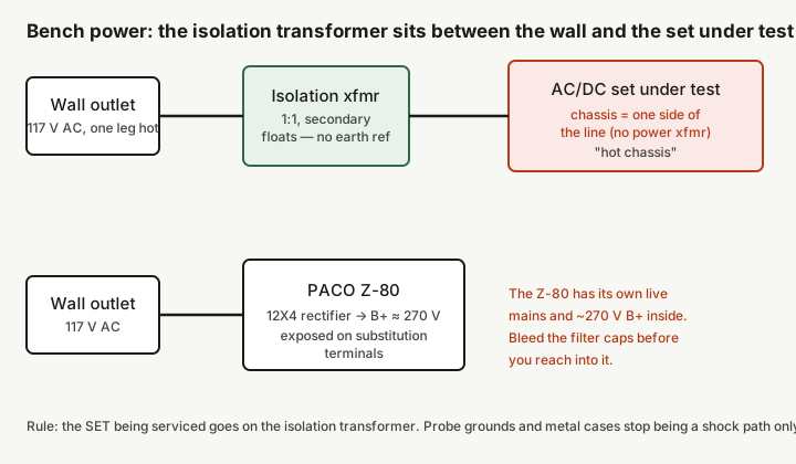
The Z-80 runs on 117 V AC mains (a 220 V option existed). Its 12X4 full-wave rectifier develops a B+ of roughly 270 V, and — this is the part that surprises people — that B+ is deliberately brought out to the speaker/output-transformer substitution terminals. Those terminals exist so you can swap the Z-80’s own audio output transformer and speaker in for a suspect one in a radio under test, which means they carry the full plate supply of the output stage. Treat every substitution terminal as a live ~270 V point whenever the box is powered, and treat the filter capacitors as charged to that voltage for a while after you switch off.
Standard tube-era discipline applies without exception:
- Bleed the B+ before you reach in. The filter electrolytics hold charge. Clip a bleeder resistor (10 kΩ, a couple of watts) across the main filter cap after power-down and confirm 0 V with a meter before your fingers go anywhere near the terminal strips. Do not trust “I turned it off a minute ago.”
- One-hand rule. When the box is live, keep one hand in your pocket. Current across the chest is what stops hearts; current from one hand to a probe tip is survivable far more often.
- Respect the substitution terminals specifically. They are the least obvious ~270 V point because they look like innocuous speaker screws.
5.2.2 Hazard two: the hot chassis on the other side of the bench
This is the bigger and more insidious risk, and it has nothing to do with the Z-80’s internals. Many of the AM radios and TV chassis you will trace with this instrument are AC/DC “hot-chassis” sets — no power transformer, the chassis tied directly to one side of the incoming line. Depending on how the set is plugged in, that chassis can be sitting at full line potential relative to earth.
The moment you clip the Z-80’s probe ground to a hot chassis, everything conductive on the Z-80 — its own metal case, its terminal screws — can go to line potential too. Now you have two boxes on the bench, both potentially hot, and you standing between them. This is the classic way a careful person gets hurt: they were being cautious about the instrument and never thought about the victim.
5.2.3 Isolation-transformer discipline
The fix is old and non-negotiable: the set under test goes on an isolation transformer. A 1:1 isolation transformer floats the secondary so that neither leg is referenced to earth. With the DUT floating, its chassis is no longer a shock path to ground, and clipping the tracer’s ground to it stops being a way to electrify the tracer.
Practical rules:
- The radio or TV under test is what goes on the isolation transformer. The Z-80 does not strictly need to be on it, but running both the DUT and the tracer through a metered isolation source (a Variac-plus-isolation unit) is the calmest way to work — it lets you bring the DUT up slowly and keeps ground references sane.
- Do not defeat the safety-ground on your own bench wiring to “solve” a hum problem. Fix the ground reference at the DUT with isolation, not by lifting grounds on the instruments.
- If you only own one isolation transformer, it belongs under the hot-chassis set, every time.
5.2.4 Assume hazardous materials until proven otherwise
Everything in this box predates modern materials rules. The original filter electrolytics and any wax/paper capacitors are of an era where PCB-bearing dielectrics and other nasties turn up. Do not cut, burn, or heat old capacitors to open them for curiosity; bag and bin the ones you remove. If the transformer runs hot or smells, stop — old transformer potting compounds are not something to cook in a poorly ventilated space.
5.3 Recapping: what to replace and how
Recapping is 90% of what “refurbishing” a Z-80 actually is. Old wax/paper coupling and bypass capacitors leak DC; old electrolytics lose capacitance and gain equivalent series resistance. Both faults degrade an amplifier’s gain, add hum, and — for the coupling caps — can shift the operating point of the next tube badly enough to redplate or distort. In a signal tracer, a leaky coupling cap shows up as hum you can’t null, a mushy or asymmetric magic-eye response, and audio that sounds wrong on the speaker. Since the whole value of a tracer is that you trust what it tells you, drifted caps are not cosmetic here — they make the instrument lie.
5.3.1 The capacitor census
Before pulling anything, map the box. Photograph the wiring, then list every capacitor by location, marked value, and marked voltage. Three families:
- The main filter electrolytics — the reservoir and smoothing caps immediately after the 12X4 rectifier. These see the full ~270 V B+ and do the most thermal work. They are the first suspects for hum and for a slow-rising or unsteady B+.
- The wax/paper coupling and bypass caps — the small tubular units between and around the 12AV6, 12AU6, and 12AQ5 stages. In a 60-plus-year-old instrument, plan to replace all of them on principle; they are cheap, and testing each one in-circuit is slower than just swapping it.
- Small mica/ceramic caps — these are typically stable and rarely need replacement unless a specific fault points at one. Leave them unless measurement condemns them.
5.3.2 Electrolytics — reform or replace
Two defensible approaches:
- Replace outright. Modern radial electrolytics of equal or slightly higher capacitance and equal-or-higher voltage rating (a 350 V or 400 V part for a ~270 V rail) drop in fine. If the original is a multi-section can, you can gut and restuff it to preserve the look, or mount modern caps underneath and leave the can as a dummy. Match or modestly exceed the marked µF; do not wildly over-size the reservoir cap or you stress the 12X4 with a bigger inrush charge current at each power-on.
- Reform, then decide. If you want to try saving the originals, reform them: bring the voltage up slowly (a Variac, or a current-limited supply) over tens of minutes while watching leakage current fall. A cap that reforms to low leakage and holds its rated voltage may be serviceable. In practice, for an instrument you intend to trust, reforming is a diagnostic step — if a filter cap needs coaxing to behave, replace it.
Record before/after: “reservoir electrolytic measured 22 µF / ESR 9 Ω against 40 µF marked — replaced with 47 µF / 400 V, ESR <1 Ω.” That line in the log is worth more later than any amount of “recapped the supply.”
5.3.3 Wax/paper coupling and bypass caps
These are the ones that will actually bite the circuit’s behavior. A wax/paper coupling capacitor that leaks even a fraction of a microamp of DC puts a positive bias on the grid of the following tube, dragging its operating point off and, in an output stage like the 12AQ5, potentially into excessive dissipation. Replace them with modern film capacitors — polyester/polypropylene, sometimes sold as “orange drops” or WIMA MKS/MKP-class parts — at the same capacitance and a voltage rating comfortably above the local B+ (400 V or 600 V film parts are common and cheap).
Values in this box are the ordinary small ones of the era — coupling caps in the low nanofarads to ~0.05 µF range, cathode and screen bypasses larger. Match the marked value; the exact dielectric does not matter for audio-frequency service as long as voltage rating and capacitance are right. Leakage is the enemy, and any modern film cap has essentially none.
5.3.4 Method and measurement
- Work one capacitor at a time, and put the new part in before you cut the next old one out — that keeps you from losing track of the wiring.
- Keep leads short on the coupling caps around the high-gain input stage (the 12AV6/12AU6 side). This is a high-gain amplifier; sloppy long leads there invite hum and instability.
- After the coupling caps, re-check DC bias at each tube if you can — the point of replacing leaky couplers is to restore clean grid bias, so verify it landed where it should.
- Log every part: location, old value/condition, new part number.
5.4 The 1629 magic-eye tube
The Z-80’s only visual indicator is a 1629 electron-ray “magic-eye” tube — there is no moving-coil meter in this instrument. The eye and the speaker run in parallel off the amplifier output: you hear the traced signal on the 5-inch speaker and see its level as the shadow angle of the eye closes. When the 1629 is tired, the instrument still works by ear, but the visual half of it becomes untrustworthy, and since the eye is often how you judge relative level from stage to stage, a weak eye quietly degrades the whole workflow.
5.4.1 Why the eye fades
A magic-eye tube is a tiny CRT: a fluorescent target coated in phosphor, driven by a triode section that controls where the “shadow” falls. Two things age:
- The phosphor dims. The target’s fluorescent coating loses brightness with hours of use, so a fully driven eye that once glowed a sharp green now looks pale and washed-out even at full deflection. This is the classic worn magic-eye symptom and it is not repairable — it is wear of the coating.
- The triode section loses emission, so the shadow no longer closes fully or no longer opens the way it should. That can mimic phosphor wear but is a different failure.
Either way, a 1629 that has been running for decades is commonly the single most degraded active device in the box.
5.4.2 The 1629 specifically — sourcing and substitution
The 1629 is a WWII-surplus staple: it is the electron-ray indicator used in ARC-5 command sets (military type VT-138) and it turned up in a lot of postwar kit gear precisely because it was cheap and plentiful as surplus. Electrically it behaves like the familiar 6E5/6U5 family of eyes, but with two differences that matter when you go shopping:
- Heater: 12.6 V at 150 mA — not 6.3 V. That 12.6 V heater is a natural fit for this set: it matches the 12-volt heaters of the other tubes (12AV6, 12AU6, 12AQ5) so the whole complement strings together on one heater voltage. Do not drop a 6.3 V 6E5/6U5 into the 1629 socket expecting it to work — the heater voltage is wrong.
- Base: octal. The 1629 uses an octal base, so it is not pin-compatible with the 6-pin-based 6E5/6U5 eyes without an adapter and a heater-voltage change.
Good NOS 1629s still exist because so many were made for the war, and they are among the more available vintage eyes. Buy from a seller who will guarantee the eye actually lights and deflects — a “tests good” tube tester reading on an eye does not tell you the phosphor is still bright. When you get one, run it a while and look at it.
5.4.3 Living with a dim eye
If a bright replacement isn’t on hand, the instrument is still fully usable by ear. Two honest coping tactics, neither of which “fixes” a worn eye:
- Judge signal presence and relative level by the speaker and use the eye only as a coarse confirm.
- Do not chase eye brightness by pushing more drive at it — you cannot restore worn phosphor with voltage, and over-driving an already-weak eye just wears the remaining coating faster.
Replace the eye when you can, and treat it as a consumable — it is the one tube in this box that is genuinely expected to wear out.
5.5 The probe and its cable
The single switched probe is the business end of the whole instrument, and on a stored unit it is often the most degraded accessory — original PACO probes are frequently missing, incomplete, or cracked. The factory probe carried a tip switch that put the RF demodulator element in or out of circuit, so one probe served both RF (crystal-rectifier demodulation) and straight audio. Many owners who have lost the original substitute a two-probe set instead — one RF/demodulator probe, one audio probe — which is a practical equivalent, not the factory arrangement.
5.5.1 The germanium demodulator diode
In the RF position, the probe demodulates by running the RF/IF signal through a germanium crystal diode — the manual calls for a crystal rectifier. Germanium diodes of that age can go leaky or open. If the RF trace is dead or weak while the audio side works, suspect the diode first. Replacements are ordinary small-signal germanium parts — 1N34A, 1N48, 1N60, or 1N270-class diodes all serve. Use germanium, not silicon: the ~0.2–0.3 V forward drop of germanium is what lets the probe demodulate small signals; a silicon diode’s ~0.6 V threshold will swallow weak traces.
5.5.2 The blocking capacitor
The demodulator diode works with a small blocking capacitor — about 0.01 µF — that passes RF/AF while keeping any DC on the circuit under test out of the tracer. On the audio side the probe is essentially just a blocking cap (in the ~0.001–0.01 µF range) with no diode, passing audio straight through to the amplifier. If you are rebuilding a probe, these are film or ceramic parts rated well above any voltage you might touch — and remember you may be probing points sitting on B+, so give the blocking cap plenty of voltage margin.
5.5.3 The cable and the sheath
The rubber on 60-year-old probe cable goes hard and cracks; the shield can short to the center conductor where the insulation has failed, which shows up as intermittent, crackly, or dead traces that change when you flex the lead. If the sheath is perished, re-cable the probe with modern shielded lead rather than trying to nurse crumbling rubber. Keep the shielded return intact all the way to the probe body — an unshielded run into a high-gain amplifier front end will pick up hum and hash that looks like a circuit fault in whatever you are testing.
5.6 The rest of the box — tubes, speaker, and mechanicals
- The other four tubes (12AV6, 12AU6, 12AQ5, 12X4) are common, cheap types. Test them, but do not reflexively replace them — unlike the magic eye, these are not expected to be worn out just from age. Replace on evidence: low emission on a tester, or a fault that traces to a specific tube. Keep a spare 12X4 rectifier around, since a soft rectifier is a common cause of low or slow-rising B+ and reveals itself as weak overall gain and heavy hum.
- The 5-inch PM speaker is worth a look and a listen. Cones of this age can be dried, torn at the surround, or rubbing at the voice coil. A rubbing or torn speaker colors everything you hear on the tracer — which matters, because the speaker is half the readout. Re-cone or replace if it buzzes or rubs.
- Sockets and switches. Decades of oxidation make for intermittent contacts. Clean tube-socket pins and exercise the attenuator/mode switch with a proper contact cleaner; scratchy attenuator action or a trace that comes and goes as you wiggle a tube is almost always dirty contacts, not a dead part.
- The wattmeter outlet and substitution terminals. These are passive — an outlet in series with the wattmeter sense, and terminals across the output transformer/speaker. There is nothing to recap here, but confirm the wiring is intact and, again, remember the substitution terminals are a live ~270 V point in use.
5.7 First power-up: do it once, through a limiter
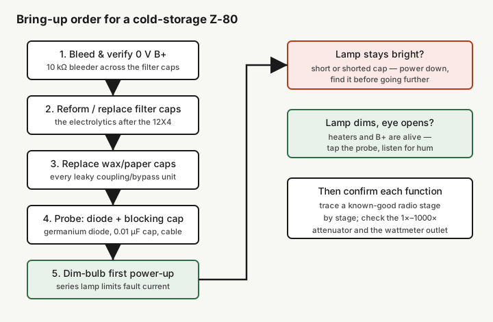
After the caps are in and the probe is sound, resist the urge to just plug it in. A box that has been cold for decades can have a marginal cap or a wiring error, and the safe way to find out is a dim-bulb tester — an incandescent lamp in series with the mains. If something inside is shorted, the lamp lights fully and drops the voltage, limiting the fault current instead of letting it blow the rectifier or cook the transformer.
Bring-up sequence:
- Bleeder confirmed, B+ reads 0 V, hands clear.
- Power through the dim-bulb tester (and, ideally, up a Variac so you can raise the line slowly).
- Lamp stays bright → there is a short or a shorted new cap. Power down and find it before going further. This is exactly what the dim-bulb tester is for.
- Lamp settles to a dim glow, heaters light, the magic eye opens → heaters and B+ are alive. Let it warm, then tap the probe tip with a finger and listen for the amplified hum/buzz on the speaker as a first sign the amplifier is passing signal.
- Confirm the attenuator sweeps gain smoothly across its 1×–1000× range, then trace a known-good radio stage by stage to prove the RF and audio paths and to see the eye deflect on real signal.
Only after that trust-building pass is the Z-80 a bench instrument again rather than a box you hope works. Operating it in earnest — front end to IF to detector to audio, reading the eye and listening on the speaker, and using the substitution outputs and wattmeter — is covered in Vol 4; the tube complement, functions, and where this box sits against the generators and injectors it is so often confused with are collected in the Vol 6 cheatsheet.