PACO Z-80 Audio-RF Signal Tracer · Volume 6
PACO Z-80 — Vol 6: Cheatsheet + Context
Quick reference, the tube complement, and where the tracer sits
6.1 The bench-side sheet
This is the reference to keep near the unit: the tube complement, the function list, the numbers worth remembering, and — the part most people get wrong — an honest placement of the Z-80 against the instruments it is constantly confused with. When the chassis is open and the schematic is on the other side of the room, this is the sheet to glance at.
Two facts anchor the whole reference and are worth stating before anything else, because almost every misdescription of this instrument violates one of them:
- The Z-80 is a signal tracer. It does not generate or inject a signal. Its only job is to take a signal that is already present in a live circuit and make it audible and visible. When you read that “the Z-80 injects a signal,” the source is wrong.
- The visual indicator is a 1629 magic-eye tube, an electron-ray device. There is no moving-coil (D’Arsonval) panel meter on this instrument. The “meter” is the eye.
6.2 At-a-glance quick reference
Table 1 — At-a-glance quick reference
| Item | Value / detail |
|---|---|
| Manufacturer | PACO Electronics Co. — kit-line brand / division of Precision Apparatus Co. |
| Nameplate address | 70-31 84th St., Glendale 27, Long Island, N.Y. |
| Model | Z-80 (PACO “Z” = signal-tracer series; unrelated to the Zilog Z80 CPU) |
| Class | Audio + RF signal tracer, tube-era |
| Era | Manual dated 1957; cataloged build approx 1960 |
| Sold as | Kit and factory-wired (kit was the common/cataloged form) |
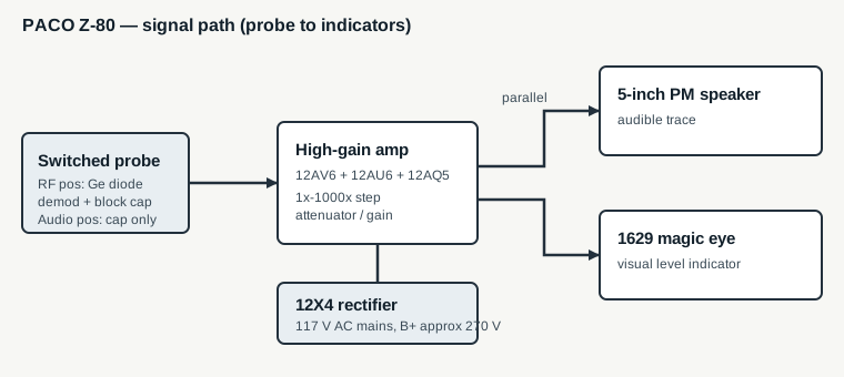
| Tubes | 12AV6, 12AU6, 12AQ5, 12X4 (rectifier), 1629 (magic eye) — five total |
| Solid-state device | One germanium crystal diode (RF-demod, in the probe) |
| Probe (factory) | Single probe with a tip switch: RF (diode-demod) + audio |
| Amplifier | Internal high-gain amp with a 1x-to-1000x step attenuator / gain control |
| Audible indicator | 5-inch permanent-magnet dynamic speaker |
| Visual indicator | 1629 electron-ray “magic eye” tube (in parallel with the speaker) |
| Extra functions | Output-transformer / speaker substitution terminals; AC wattmeter load outlet; noise / mic / pickup / tuner input testing |
| Power | 117 V AC mains (220 V option noted) |
| B+ | Full-wave rectified, approx 270 V (present on some substitution terminals) |
| Case | Approx 295 x 195 x 150 mm (11.6 x 7.7 x 5.9 in) |
| Weight | Approx 2.9 kg (6 lb 7 oz) |
| What it is NOT | Not a signal generator, not a signal injector, not a moving-coil meter |
6.3 Tube complement
Five tubes, and every one earns its socket. Four of the five run 12-volt heaters, which is why the 1629 — with its 12.6 V / 150 mA heater — was chosen over the more familiar 6-volt 6E5/6U5 magic eyes: its 12.6 V heater matches the Z-80’s other 12-volt tubes, so it runs straight off the same 12.6 V heater supply.
Table 2 — Tube complement
| Tube | Type | Role in the Z-80 |
|---|---|---|
| 12AV6 | Twin-diode / high-mu triode | Voltage-amplifier / detector stage at the front of the audio chain |
| 12AU6 | Sharp-cutoff pentode | High-gain amplifier stage |
| 12AQ5 | Beam-power output pentode | Audio output — drives the 5-inch speaker and the output transformer |
| 12X4 | Full-wave rectifier | Produces the approx 270 V B+ supply from the mains transformer |
| 1629 | Electron-ray indicator (“magic eye”) | The visual level indicator; octal base, 12.6 V / 150 mA heater |
A note on the 1629 that matters for restoration: it is electrically similar to the 6E5/6U5 pattern but is an octal-based, 12.6-volt part that saw heavy WWII use (VT-138, ARC-5 gear) and then flooded the postwar surplus market — which is exactly why a budget kit maker reached for it. It is the tube most likely to be dim or dead on a unit that has sat, and it is the one to source ahead of a restoration. Aging and replacement of the 1629 are covered in Vol 5.
The germanium crystal diode is not a tube but belongs in any parts count: it lives in the probe and does the RF/IF demodulation when the probe’s tip switch is in the RF position. Common owner replacements are 1N34A / 1N48 / 1N60 / 1N270-class germanium diodes with an approx 0.01 uF blocking capacitor. The circuit detail is in Vol 3.
6.4 Function list
The Z-80 is a tracer first and a small collection of service conveniences second. The complete, verified function set:
- RF signal tracing. Probe in the RF position; the germanium diode demodulates the modulation envelope off an RF or IF carrier, and you hear/see the recovered audio.
- Audio signal tracing. Probe in the audio position (blocking cap, no diode); audio passes straight into the amplifier.
- High-gain amplification with a 1x-to-1000x attenuator. The same amplifier serves every mode; the step attenuator keeps a strong detector-stage signal from pinning the eye and a weak antenna-stage signal from vanishing.
- Speaker / output-transformer substitution. The “transformer connections” terminals expose the Z-80’s own output transformer and speaker so they can stand in for a suspect transformer or speaker in the set under test. Caution: these terminals can carry the full approx 270 V B+ — see the safety note.
- AC wattmeter. A load-outlet function: plug the set under test into it to read its AC power draw. The exact readout method — whether the magic eye, a marked scale, or a calculation — isn’t clear from surviving catalog material, so the function is certain but the way you read the value is not.
- Noise / input testing. Amplifier-input checks of phono pickups, microphones, and tuners, plus listening for noise in a circuit under test. This is a diagnostic listening mode, not a noise-generator — the Z-80 does not source noise.
Operating detail for each of these lives in Vol 4; the circuit behind them is Vol 3.
6.5 Where the tracer sits
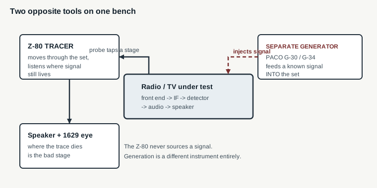
This is the section that keeps the instrument from being mislabeled. A signal tracer and a signal generator are mirror images, and the Z-80 is firmly on the tracer side.
6.5.1 Tracer versus generator / injector
A signal generator / injector produces a known signal and feeds it into a circuit. You inject at one stage and listen at the set’s own speaker; if it comes through, everything downstream is good. In the PACO catalog that job belongs to a separate product line — the G-30 / G-34 RF and marker generators (roughly 160 kHz to 240 MHz). It is a different box on the bench.
A signal tracer — the Z-80 — is a portable amplifier with its own speaker and indicator that you move through a live circuit to find where a signal that should be present has stopped. You probe stage by stage from the front end toward the speaker; where the trace dies is the bad stage. The Z-80 never sources anything. It only listens.
The two techniques are complementary, and a well-equipped tube-era bench had both: a generator to supply a clean signal at the antenna (or to align IF cans on frequency) and a tracer to walk that signal through the chassis. The Z-80 is the listening half of that pair, not the whole pair.
6.5.2 Against the sibling PACO line
The Z-80 is one instrument in a broad PACO / Precision Apparatus test-gear catalog. Knowing the neighbors keeps the model numbers straight:
Table 3 — The Z-80 is one instrument in a broad PACO / Precision Apparatus test-gear catalog. Knowing the neighbors keeps the model numbers straight
| PACO model(s) | What it is | Relationship to the Z-80 |
|---|---|---|
| G-30 / G-30PC / G-34 | RF signal / marker generators | The generator function people wrongly attribute to the Z-80 lives here |
| 660 / 910 / T-60 / T-61 / T-62 / T-63 | Tube testers | Different job entirely |
| V-70 | VTVM | The bench voltmeter, not a tracer |
| S-50 / S-55 | Oscilloscopes | The visual-analysis instrument |
Within its own series, the Z-80 does not appear to split into feature-differentiated sub-variants; the meaningful distinction is kit versus factory-wired, not a model fork.
6.5.3 Against the competition of its day
PACO and EICO were the two dominant names in budget signal-tracer kits in the late 1950s, with Heathkit and other kit makers also in the field. The Z-80 is PACO’s higher-end tracer, and its distinguishing traits against the field are the magic-eye-plus-speaker dual indication, the wide 1x-to-1000x attenuator range, and the bundled substitution and wattmeter conveniences — features that pushed it past a bare probe-and-speaker tracer.
6.5.4 Against the modern bench
Signal tracing did not disappear; the instrument changed. Today the same “walk the signal until it dies” method is done with an oscilloscope (with a demodulator or detector probe for RF/IF work) or a spectrum analyzer, both of which show far more than an eye tube and a speaker can. What the Z-80 still offers is speed and directness on exactly the gear it was built for: a tube AM/FM radio or a tube TV audio strip, where a trained ear on the speaker and a glance at the eye localize a dead stage faster than setting up a scope. On a period chassis, it remains a genuinely useful first-reach instrument, not a museum piece.
6.6 Safety quick note
Full mains and HV discipline is Vol 5; the one-line reminders that belong on the bench card:
- 117 V AC mains inside the case, and roughly 270 V B+ on the substitution terminals. Bleed B+ before reaching in; one-hand rule above about 50 V.
- The substitution terminals can be live at B+ — treat them as hot, not as harmless speaker lugs.
- The radios and TVs under test are often AC/DC “hot-chassis” sets. Use an isolation transformer on the equipment under test as a matter of routine, not as an afterthought.
6.7 Owner’s unit
6.8 Cross-references
- Vol 1 — Overview: what a signal tracer is, the Z-80’s provenance, why it is on the bench.
- Vol 2 — Signal tracing and where the Z-80 fits: the tracer-versus-injector distinction in depth, the tube-era service bench, comparison to EICO/Heathkit.
- Vol 3 — Hardware and circuit: the switched probe, the amplifier and attenuator, the tube-by-tube circuit, the substitution and wattmeter functions.
- Vol 4 — Operating it: stage-by-stage tracing of a dead AM/FM/TV chassis, reading the eye and the speaker, using the substitution outputs and the wattmeter.
- Vol 5 — Refurbishing: recapping, the aging 1629, probe and cable repair, mains/HV/hot-chassis safety.