Simpson 260 Series 8 · Volume 3
Simpson 260 — Vol 3: How It Works — Movement, Circuit & Reading the Scales
Inside the 100 MΩ ladder, the two-battery ohmmeter, and the mirror that makes a needle honest.
3.1 Scope of this volume
Vol 1 made the case for keeping an analog VOM on the bench; Vol 2 walked the nine series and what changed between them. This volume is the schematic-grade middle layer — how a Series 8 (or 8P, or any series sharing the same architecture back to the 1970s) actually turns a voltage, a current, or a resistance into a needle position, and how to read what the needle is telling you once it gets there.
Everything here traces back to one part: a 50 µA D’Arsonval moving-coil movement. Every function — DC volts, AC volts, DC current, ohms, dB — is a different piece of analog electronics arranged to push somewhere between 0 and 50 µA through that one coil. Understand the movement and the rest of the instrument is “how do I get exactly 50 µA through this coil when the input is at full scale,” six different ways.
Note — Facts below are drawn from Simpson’s own 260-8 and 260-8P instruction manuals (the two primary sources with a full Table 1-1) plus the collector literature at simpson260.com. Where the manuals don’t publish a number — the individual multiplier-resistor values, for instance — that gap is stated rather than guessed at.
3.2 The movement — 50 µA D’Arsonval core
3.2.1 What a D’Arsonval movement does
A D’Arsonval (moving-coil, permanent-magnet) movement is the mechanical heart of every function on the 260. A lightweight coil of fine wire sits in the radial field of a permanent magnet; current through the coil produces a torque proportional to that current, which the coil’s suspension (see §1.2) converts into a rotation, which a pointer converts into a deflection across the scale. Restoring torque comes from the suspension itself — spiral hairsprings on a pivot-and-jewel movement, or torsional stiffness of the ribbon itself on a taut-band movement — so deflection is (ideally) linear in coil current.
The 260’s movement is specified as 50 µA full scale, with a 250 mV drop across it at that current [CONFIRMED — primary, 260-8/8P Table 1-1, DC Microamperes range]. Dividing gives a movement resistance on the order of
$$ R_{movement} \approx \frac{250\text{ mV}}{50\text{ }\mu\text{A}} \approx 5{,}000\ \Omega $$
This is a derived, order-of-magnitude figure [LIKELY — not published by Simpson as a coil-resistance spec; back-calculated from the two published numbers above]. Every other range on the meter — every DC volt range, every AC volt range, every current range, every ohms range — is built by adding some external network in series or in parallel with this one 50 µA / 250 mV movement so that “full scale” on that network corresponds to exactly full-scale current through the coil.
Damping and mechanical zero. Two mechanical details finish off the movement picture, both of which resurface in Vol 4’s operating procedure and Vol 5’s calibration section. The coil’s own motion in the magnet’s field induces a small back-EMF that opposes rapid movement — an intrinsic form of electromagnetic damping that keeps the pointer settling smoothly rather than overshooting and oscillating around the true reading, the same principle that makes the needle smooth out a noisy or fluctuating signal rather than jitter with it (Vol 1’s opening argument for keeping an analog meter on the bench). Independent of any electrical input, the pointer also has a mechanical zero adjustment — a small screw-slot control below the meter face that lets the user re-center the pointer at true zero with no leads connected, compensating for the suspension settling slightly out of true over years of use and handling. Checking (and if needed resetting) mechanical zero is the first step of Vol 4’s operating procedure, before any measurement is attempted.
Table 1 — 1.1 What a D'Arsonval movement does
| Movement parameter | Value | Confidence |
|---|---|---|
| Type | D’Arsonval moving-coil, permanent-magnet | [CONFIRMED] |
| Full-scale current | 50 µA | [CONFIRMED — primary] |
| Full-scale voltage drop | 250 mV | [CONFIRMED — primary] |
| Approximate coil resistance | ≈ 5,000 Ω | [LIKELY — derived] |
| Suspension | pivot-and-jewel (orig.–Series 5) → taut band (5M option, standard Series 6+) | [CONFIRMED] |
| Dial | plain (orig.–Series 3A/4) → mirrored option (4M–7-series) → mirrored standard (Series 8+) | [CONFIRMED] |
| Damping | intrinsic (electromagnetic, back-EMF of coil motion) | [LIKELY — general D’Arsonval principle] |
| Zero adjustment | external screw-slot, mechanical | [LIKELY] |
3.2.2 Pivot-and-jewel vs. taut-band suspension
The 260 line spans two suspension technologies, and getting the history right matters — this is, per the genealogy research, the single most commonly mangled 260 fact online.
- Pivot-and-jewel: the coil assembly rides on a pair of steel pivots seated in jeweled bearings (like a wristwatch), restrained by spiral hairsprings that also carry current into and out of the coil. This is the original 260’s suspension and remains the base-model suspension through Series 5 [CONFIRMED]. From Series 3A on, the pivot-jewel movement is additionally self-shielding with spring-loaded jewels — a shock-tolerance improvement that keeps the pivot-and-jewel technology but cushions it against drops [CONFIRMED].
- Taut-band: the coil is suspended on a pair of thin, tensioned metal ribbons instead of pivots — no bearings to wear, stick, or shock-damage, and no jewels to chip. Restoring torque comes from the ribbons’ torsional stiffness.
The trap to avoid — taut-band suspension did not debut on Series 8. It first appears on the Series 5M (~1969) as an “M” option layered onto the Series 5 platform, and becomes the standard suspension starting with Series 6 (~1973) [CONFIRMED — simpson260.com: “The Simpson 260-5M has Taut Band Suspension and a mirrored dial”; radiomuseum: “the difference between 4M and 5M is that the 5M has Taut Band Suspension”]. Series 6, 7, and 8 are all taut-band. What is true of Series 8 is that taut band is standard on it (as it is on 6 and 7) — see Vol 2 §“Movement evolution” for the full walk.
The 4M is the trap inside the trap: it has the mirrored dial (see §1.3) but is still pivot-and-jewel — mirror and taut band arrived one series apart, mirror first (4M, ~1963–66), taut band second (5M, ~1969) [CONFIRMED]. An unwary author (or eBay listing) conflates the two because they read “mirrored dial, has an M in the name” and assumes taut band comes along for free. It doesn’t, on a 4M.
Practically, on the bench: a taut-band movement (Series 6 on, including both of Jeff’s units — the 8 and the 6P) tolerates rougher handling and won’t develop the sticky, jewel-wear symptoms an older pivot-and-jewel movement can. See Vol 5 §“Meter-movement issues” for the failure-mode detail.
3.2.3 The mirror-backed dial and parallax
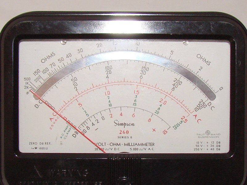
Starting with the 4M (~1963–66), Simpson began offering a mirror-backed scale — a narrow strip of mirror running behind the arc of the pointer, between the printed scale and the pivot. The mirror does not change the electronics at all; it exists purely to defeat parallax, the apparent shift in a pointer’s position against a scale caused by viewing it from an angle instead of dead-on. On a non-mirrored dial, two people looking at the same needle from slightly different angles can read slightly different numbers, and neither is provably wrong.
Mirror status by series, in one line: optional from the 4M (~1963–66) through Series 7 (an “M” suffix model, layered onto whichever suspension that series otherwise has), standard from Series 8, which is exactly why “Series 8” carries no trailing “M” — the M-feature became universal and the letter was retired [CONFIRMED — simpson260.com: “the mirrored scale is standard on the Series 8, note there is no ‘M’ in the series number”]. See §5 below (“Reading the Scales”) for how to actually use the mirror.
3.3 The rotary switches — range and function
The 260’s controls are two rotary (wafer) switches, not a lever mechanism of any kind — a distinction worth stating plainly because “lever-style selector” shows up in enough secondhand descriptions of analog VOMs that it’s worth killing here.
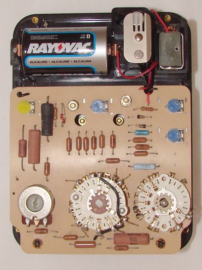
- The RANGE switch — the large front-panel knob — selects which tap on the internal resistor network (voltmeter multiplier bank, current shunt, or ohms range) is connected between the input jacks and the movement. It is a wafer-type rotary switch: a stack of phenolic or PCB wafers, each carrying a ring of fixed contacts, wiped by a spring contact riding on a common rotating shaft. Later series (Series 3 on) mount these wafers on a printed circuit board rather than hand-wiring them [CONFIRMED — primary: Series-1 page notes “extensive hand-wiring, no PCB”; later-series manuals describe “most parts on a printed circuit board”].
- The Function switch (labeled +DC / −DC / AC on most series) sets polarity and rectifier routing — whether the movement sees the raw DC current directly (with a chosen polarity) or the rectified output of the AC path (§4 below). From Series 7 on this switch adds an “OFF/transit” position that disconnects the movement entirely for safe carrying [CONFIRMED — Vol 2 §“Series-identification guide”].
Both switches are wafer contacts riding under spring pressure — which is exactly the mechanism that oxidizes with age and disuse and needs periodic DeoxIT + cycling. See Vol 5 §“Range-selector wafer / contact oxidation” for the service procedure.
Mechanically, a wafer switch stacks several flat, disc-shaped wafers (phenolic on the earliest hand-wired series, PCB material from Series 3 on) on a common center shaft, each wafer carrying a printed or etched ring of fixed copper/brass contact pads around its circumference. A spring-loaded wiper — a small leaf-spring contact riding under its own tension — sits on the same shaft and sweeps across that ring of pads as the shaft rotates, making contact with exactly one pad (or, momentarily, bridging two adjacent pads mid-rotation) at each click-stop. Detents — small spring-loaded ball or leaf catches engaging notches on the shaft — give the switch its tactile click and hold it precisely on each contact rather than letting it drift between positions. Multiple wafers stacked on the same shaft let one switch knob simultaneously make or break several independent circuits at once — which is exactly how a single RANGE knob can reconfigure the voltmeter ladder, the current shunt, and the ohms-range battery selection all in the same rotation, each on its own wafer, without the user ever needing to think about which internal network is being switched.
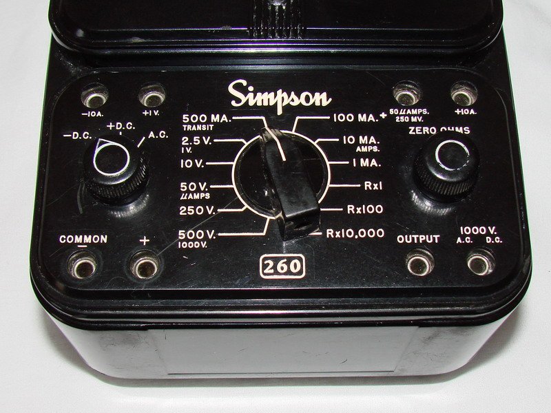
Note — the 5000 V range is not a switch position at all. There is no “5000 V” click-stop on the RANGE switch. Instead, the panel carries a dedicated “5000 V.” jack, and 5000 V DC/AC measurements are made by plugging in an external high-voltage probe and reading the meter on one of its normal high-range positions (the probe itself does the additional attenuation). See §3.3 below and Vol 4 §“Output and dB” / Vol 5 §“Parts sourcing” for the probe.
3.4 DC voltmeter — the series-multiplier ladder
3.4.1 The idea: a fixed ohms-per-volt, at every range
Every DC voltmeter is built from the same two-part recipe: a sensitive current movement, plus enough series resistance ahead of it that the movement reads full scale at exactly the voltage you want that range to represent. Because the movement always needs the same 50 µA to hit full scale, and Ohm’s law says $R = V/I$, the total resistance the meter presents (multiplier bank + movement) at any DC volt range is simply:
$$ R_{range} = \frac{V_{FS}}{50\ \mu\text{A}} = V_{FS} \times 20{,}000\ \Omega $$
That constant — 20,000 Ω per volt of range — is the 260’s headline DC sensitivity figure, and it is not a marketing number; it falls straight out of the 50 µA movement. Simpson states the identical derivation from the top of the ladder [CONFIRMED — primary theory-of-operation, 260-8/8P manuals]: the multiplier bank plus movement together total 100 MΩ measured from the “5000 V.” jack to COMMON−, and
$$ \frac{100{,}000{,}000\ \Omega}{5{,}000\text{ V}} = 20{,}000\ \Omega/\text{V} $$
— the same 20 kΩ/V figure, derived from the top of the ladder instead of from the movement, as a consistency check. Both routes to the number agree because they describe the same physical resistor chain.
Cross-reference — this 20 kΩ/V figure is also why the 260 loads circuits far more than a modern DMM’s ~10 MΩ input, and why Vol 1 opens with a counter-intuitive point: that loading is a feature on low-impedance power and filament work, because it rejects phantom/induced voltages that fool a DMM — but it is the wrong tool for a high-impedance grid, screen, or AVC node. Reach for the B&K 375 VTVM (≈10 MΩ input) or the Simpson 311-2 VTVM (≈11 MΩ input) on those nodes instead — see Vol 1 §“What it is NOT.”
3.4.2 The ladder, tap by tap
The DC voltmeter is a classic series-multiplier chain: a string of precision resistors, tapped at several points, with the RANGE switch wiper selecting which tap feeds the movement’s COMMON− return. Each additional tap adds resistance so that the same 50 µA movement reads full-scale at a higher input voltage the further up the chain the wiper sits.
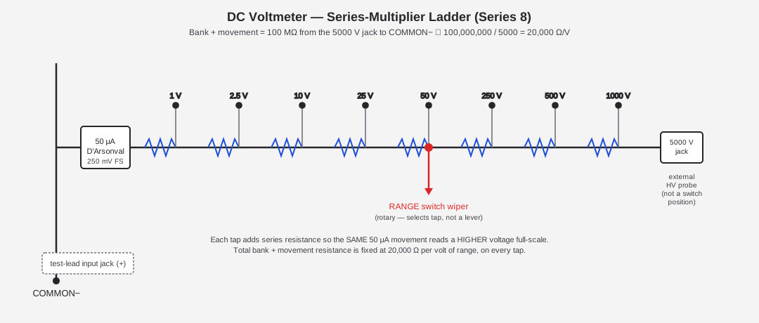
Simpson’s published DC volts ladder for Series 8/8P is:
0 – 1 – 2.5 – 10 – 25 – 50 – 250 – 500 – 1000 V [CONFIRMED — primary, Table 1-1], plus 0–250 mV on a dedicated DC-millivolts range, at 2% of full scale accuracy throughout.
The 0–25 V step is itself a series marker worth flagging here (Vol 2 covers it as part of the genealogy): it is a new range introduced with the Series 8/8P [CONFIRMED — primary, 260-8 §1.1 “New Features … 0-25V AC/DC Range”]. Earlier series ran the classic 2.5–10–50–250–1000 V ladder without the intermediate 25 V and 500 V steps that Series 8 adds.
The individual multiplier resistor values are not published in a clean table in either the 260-8 or 260-8P operator’s manuals [NOT FOUND — the surviving legible fragments of an older-series manual scan show partial figures like 15 MΩ, 150 kΩ, and 48 kΩ, plus unreadable low-value shunts, but no complete per-tap resistance table could be captured for this dive]. The complete component-level table exists in Simpson’s printed service/repair literature (the “260-3 to 6 repair instructions” document and period factory manuals) rather than the operator’s manual — a follow-up worth flagging for anyone doing component-level bench repair rather than functional-block understanding.
Worked example — sizing a hypothetical 250 V tap. Even without the exact per-resistor table, the governing math is simple enough to reconstruct for any range, and it’s worth walking through once so the “100 MΩ ⇒ 20,000 Ω/V” relationship stops being an abstraction. At the 250 V range, the total resistance the ladder must present, movement included, is $$ R_{250V} = 250\text{ V} \times 20{,}000\ \Omega/\text{V} = 5{,}000{,}000\ \Omega = 5\ \text{M}\Omega $$ Since the movement itself contributes only its own ≈5 kΩ (§1.1) — a rounding error against 5 MΩ — very nearly all of that 5 MΩ has to be added as series multiplier resistance between the 250 V jack (or the 250 V tap on a shared jack, depending on the specific jack layout for that series) and the movement. At full-scale input (250 V across ≈5 MΩ), the current through the chain is $$ I = \frac{250\text{ V}}{5{,}000{,}000\ \Omega} = 50\ \mu\text{A} $$ — exactly the movement’s own full-scale current, as it must be by construction. Every other DC volts tap follows the identical pattern: multiply the range’s full-scale voltage by 20,000 Ω/V to get the total resistance that tap must present, and the difference between adjacent taps (e.g., the 250 V tap vs. the 50 V tap) is the individual multiplier resistor value switched in or out between them.
The reason this matters beyond arithmetic bookkeeping: it’s also the source of the loading effect flagged in the cross-reference above. At the 250 V range the meter presents 5 MΩ — high enough to be a rounding error against most power-supply and filament-circuit source impedances, which is why the 260 is a fine choice there. On a lower range against a high-impedance source, though, the same math cuts the other way: at the 2.5 V range the meter presents only $2.5 \times 20{,}000 = 50{,}000\ \Omega$ — a 50 kΩ load that can measurably pull down a grid-bias or AVC node whose own source impedance is in the same neighborhood or higher, silently reporting a lower voltage than the node actually sits at when undisturbed. This is precisely the scenario Vol 1 flags as the 260’s blind spot and the VTVM’s home turf.
3.4.3 The top of the ladder — the 5000 V jack and the external HV probe
⚠ Danger — the 5000 V jack is not a “safe” high-range tap by virtue of being labeled — it exists specifically because 1000 V is the meter’s own rated ceiling (see below), and anything above that requires additional external attenuation before it ever reaches the meter’s internal ladder.
The panel carries a “5000 V.” jack at the top of the multiplier chain. This is not a RANGE-switch position — there is no click-stop labeled “5000 V.” Reaching 5000 V DC (or the extended AC range) means plugging in Simpson’s external HV probe, which contains its own additional attenuation ahead of the meter’s internal 100 MΩ bank, and reading the result off one of the meter’s ordinary high-voltage scale positions per the probe’s instructions [CONFIRMED — primary; the theory-of-operation for the ladder is explicitly written “from the ‘5000 V.’ jack to COMMON−,” describing the internal bank’s endpoint, not a switch click]. The 260’s own rated circuit-to-ground voltage is 1000 V AC/DC (per ANSI C39.5, April 1974) — everything above that is the HV probe’s job, not the meter body’s.
Note — the HV probe’s exact Simpson part number could not be confirmed against Simpson’s current accessory list during this research; do not cite a specific catalog number for it. See Vol 5 §“Parts sourcing today.”
3.5 DC current ranges — the Ayrton (ring) shunt
Current ranges work the opposite way from voltage ranges: instead of adding resistance in series to limit current into the movement, a current range adds a low-value shunt resistor in parallel with the movement, diverting most of the input current around the coil so only 50 µA ever flows through it at full scale. The 260 uses an Ayrton shunt (also called a ring shunt) — a single resistive ring tapped at several points, with the RANGE switch selecting which tap the movement bridges across. The Ayrton topology’s advantage over a bank of separate parallel shunts is that switch-contact resistance sits in series with the whole ring rather than in the signal path itself, so contact wear and oxidation on the switch don’t directly corrupt the shunt ratio the way they would on a naively-switched shunt bank.
The 260-8/8P current ranges, per Table 1-1:
Table 2 — The 260-8/8P current ranges, per Table 1-1
| Function | Ranges | Accuracy | Voltage drop at FS |
|---|---|---|---|
| DC Microamperes | 0–50 µA | 1.5% of FS | 250 mV |
| DC Milliamperes | 0–1 mA | 2% of FS | ≈250 mV |
| DC Milliamperes | 0–10 mA | 2% of FS | ≈255 mV |
| DC Milliamperes | 0–100 mA | 2% of FS | ≈300 mV |
| DC Milliamperes | 0–500 mA | 2% of FS | ≈500 mV |
| DC Amperes | 0–10 A | 2% of FS | ≈255 mV |
[CONFIRMED — primary, 260-8/8P Table 1-1]
How the ring shunt works, mechanically. Picture the Ayrton shunt as a closed loop of resistance wire with several tap points soldered along its circumference, like stops on a circular track. The movement is permanently connected across two fixed points on that ring (rather than being switched in and out directly), and the RANGE switch’s wiper selects which tap on the ring the external input current jacks connect to. Current entering at the wiper’s tap splits between two parallel paths around the ring back to the movement’s fixed connection points — most of it taking the low-resistance short way around (bypassing the coil almost entirely), a small controlled fraction taking the path that includes the movement itself. Moving the wiper to a different tap changes the ratio of ring resistance on either side of the movement’s connection, which changes the fraction of input current that reaches the coil — that’s the whole range-selection mechanism. Because switch-contact resistance at the wiper sits in series with the entire ring (both current paths pass through it) rather than in series with just the coil branch, ordinary wafer-contact wear and light oxidation don’t skew the current-division ratio the way they would if each range used its own individually-switched shunt resistor.
Two points worth flagging for anyone using these figures as bench-test values:
- The 0–50 µA range is the movement itself, unshunted — its 250 mV drop is simply the movement’s own natural full-scale drop from §1.1, not a shunt calculation. Every heavier current range then adds a shunt tap that keeps the terminal voltage drop in the same rough 250–500 mV neighborhood while diverting proportionally more current around the coil.
- The 0–10 A range is not internally fused. The shunt for this range is wired directly to the ±10 A jacks — there is no fuse Simpson intends you to rely on for over-current protection here. Never break a 10 A-range lead connection while the circuit is energized; the sudden current interruption across an unfused, low-impedance path is an arc hazard. See Vol 4 §“Safety” and Vol 6’s DON’T table for the operator-facing version of this warning.
3.6 AC voltmeter — rectifier feeding the DC microammeter
3.6.1 Why a DC movement can read AC at all
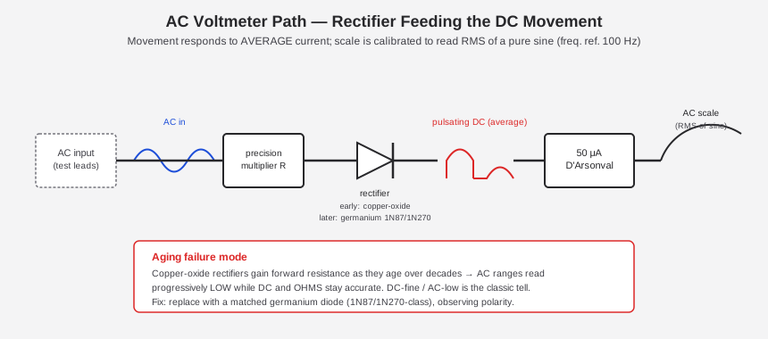
The D’Arsonval movement is fundamentally a DC device — a steady coil current produces a steady deflection; drive it with 60 Hz AC directly and the coil simply tries to follow the alternating torque, which (above a few Hz, given the movement’s mechanical inertia) it can’t — the pointer sits near zero, vibrating slightly, rather than deflecting usefully. The 260 solves this the same way essentially every analog AC-reading meter of its era did: rectify the AC first, then feed the resulting pulsating DC into the same 50 µA movement used for everything else.
3.6.2 Average-responding, RMS-calibrated
Because the movement’s mechanical inertia averages out the rectified waveform’s ripple, what the pointer actually settles on is proportional to the average value of the rectified current — not its true RMS value. Simpson’s own footnote states this plainly: the AC voltmeter “responds to the average value of an AC current, and is calibrated to indicate the RMS value of a pure sine wave” [CONFIRMED — primary footnote, 260-8/8P manuals], with the reference frequency of 100 Hz for the accuracy specification.
The practical consequence: the AC scale is only strictly accurate for a pure sine wave. Feed it a square wave, a heavily clipped waveform, or SCR-chopped AC and the reading will be off from the true RMS value by an amount that depends on the waveform’s crest factor — because the meter was never measuring RMS in the first place, it was measuring average current and multiplying by a fixed sine-wave form-factor constant baked into the scale printing. This is the same caveat that applies to essentially every average-responding analog AC meter, VOM or VTVM alike, and it’s worth remembering before trusting an AC-volts reading on anything but line-frequency sine or a clean audio sine tone.
Table 1-1’s AC volts specification:
Table 3 — Table 1-1's AC volts specification
| Function | Ranges | Accuracy | Sensitivity |
|---|---|---|---|
| AC Volts | 0–2.5–10–25–50–250–500–1000 V | 3% of FS | 5,000 Ω/V |
[CONFIRMED — primary, Table 1-1]
Note on a stray figure — one ManualsLib-hosted scan of an early 260 operator’s manual page labels the AC voltmeter circuit “1000 Ohms Per Volt” rather than 5,000. Every modern-series data table located for this dive — including both the 260-8 and 260-8P Table 1-1 — states 5,000 Ω/V AC, and that is the figure to use for Series 5 through 8. Treat the 1,000 Ω/V figure as [UNCERTAIN] — either an OCR/label error on that one scanned page or a genuine artifact of a very early, lower-sensitivity AC arrangement predating the mainstream series — but do not repeat it as the 260’s general AC sensitivity.
3.6.3 The rectifier itself — copper-oxide to germanium
The identity of the rectifying element changed over the 260’s production life, and this is directly relevant to service work because it’s a common failure point (see §5.4 and Vol 5).
- Early series (including the original 260) used a copper-oxide (metal-oxide) rectifier [CONFIRMED — primary: the early 260 operator’s manual states outright, “A.C. is rectified by a copper oxide rectifier in order to supply the microammeter with direct current”; corroborated independently by a 1955 manual].
- Later series moved to germanium diodes. The Series 5 manual specifies a 1N87 germanium diode [LIKELY — forum/collector consensus, corroborated against the Series 5 manual]; common modern substitutes cited by collectors are 1N270, 1N100, 1N276, and 1N34A-class germanium small-signal diodes, all chosen for the same reason: a low (~0.2–0.3 V) forward drop that keeps the low AC ranges reasonably linear even close to zero, where a silicon diode’s ~0.6 V knee would badly compress the bottom of the scale.
- The exact copper-oxide → germanium transition series (and any later transition to silicon) is [NOT FOUND / UNCERTAIN] in the sources available for this dive. The best-supported synthesis: copper oxide on the earliest series, germanium documented by Series 5, and the modern 260-8 using a semiconductor (germanium or silicon) diode rectifier. Do not assert a precise cutover series number — the manuals simply don’t spell one out, and the Series 7 manual in particular doesn’t name its diode type at all.
3.6.4 The “AC reads low as it ages” diagnostic
Copper-oxide rectifiers are not a “set it and forget it” component: they age, and the mechanism is a slow rise in forward resistance as the oxide junction degrades over decades of shelf/service life [LIKELY — collector consensus; this is the textbook copper-oxide-rectifier aging failure, not unique to Simpson]. Because that rising resistance sits in series with the AC signal path ahead of the movement, the symptom is specific and diagnostic:
Note — the classic tell: on an aging original-era 260, DC volts and ohms stay accurate while AC volts reads progressively low, and the error is not perfectly linear across the AC range set (it’s worse at low-signal, small-deflection readings than near full scale, because forward resistance is a larger fraction of the total circuit resistance at low current). If a 260’s DC and ohms check out against a reference but the AC volts range reads consistently low against a known-good AC source, the rectifier — not the movement, not the multiplier resistors — is the first suspect.
The fix is a straightforward like-for-like swap: replace the aged copper-oxide element with a matched germanium diode (1N87/1N270-class), observing polarity carefully, since a reversed diode simply won’t conduct on the intended half-cycle at all rather than degrading gracefully. See Vol 5 §“Rectifier, resistor drift, fuses” for the full refurb writeup, including how to confirm the fix against a reference before closing the case back up.
3.7 The ohms circuit — two batteries, one movement
3.7.1 Why an ohmmeter needs its own power
Voltage and current ranges are passive as far as the meter is concerned — the circuit under test supplies all the energy, the 260 just measures it. Resistance is different: an unpowered resistor produces no signal on its own, so the meter has to supply a small, known current through the unknown resistance itself and read the resulting voltage drop (or, equivalently, read how much of the meter’s own internal current makes it through the external resistance). That means the ohms function needs its own onboard power source — and the 260 carries two of them.
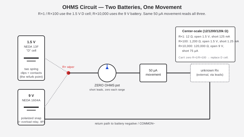
3.7.2 The two-battery arrangement (Series 6 / 6P / 8 / 8P — Jeff’s units)
On Series 6 and later — which covers both of Jeff’s instruments, the 6P and the 8 — the ohms circuit uses:
Table 4 — uses
| Battery | NEDA type | Serves | Notes |
|---|---|---|---|
| 1.5 V “D” cell | NEDA 13F | R×1, R×100 | Held by two spring-steel clips that are themselves the contacts |
| 9 V battery | NEDA 1604A | R×10,000 | Held by a spring clip plus a separate, polarized snap connector; on 8P this battery also feeds the overload relay |
[CONFIRMED — primary, 260-8/8P §1.3: “There are two batteries in the ohmmeter circuits. One is a NEDA 13F size D cell that furnishes 1.5-volts for the R×1 and R×100 ranges. A NEDA 1604 battery furnishes 9-volts for the R×10,000 range. The 1.5-volt D cell is held in place with two spring clips which also serve as battery contacts … The 9-volt battery is held in place with a spring clip, but contact is made with a separate connector that is polarized.”]
This is precisely the hardware Jeff serviced on his 6P — see Vol 5’s lead section, “Corroded battery holders.” A leaking cell in this compartment dumps electrolyte directly onto the spring-clip contacts that are the circuit path, which is why corrosion here reads as an intermittent or dead ohms function long before it becomes a visible mess.
Battery combo as a coarse dating tell — this D-cell + 9 V pairing is itself a series marker: it’s the arrangement Simpson introduced with Series 6 (~1973), replacing an earlier ~6 V pack (roughly four AA cells or two 3 V cells, depending on series) used for the high-ohms range on Series 1 through ~5. See Vol 2 §“Series-identification guide” and Vol 6’s battery-complement table for the full era-by-era progression. Do not cite 15 V or 30 V for any 260 high-ohms battery — both figures turn up in forum discussion but were not found in any primary Simpson source for the 260 and are almost certainly confusion with a different Simpson (or other manufacturer’s) meter.
3.7.3 Range, center-scale reading, and battery behavior
Table 1-1’s resistance specification for Series 8/8P:
Table 5 — Table 1-1's resistance specification for Series 8/8P
| R × 1 | R × 100 | R × 10,000 | |
|---|---|---|---|
| Range | 0–2,000 Ω | 0–200,000 Ω | 0–20 MΩ |
| Center (mid-scale) reading | 12 Ω | 1,200 Ω | 120,000 Ω |
| Nominal open-circuit voltage | 1.5 V | 1.5 V | 9 V |
| Nominal short-circuit current | 125 mA | 1.25 mA | 75 µA |
| Arc accuracy | 2.5° | 2° | 2° |
[CONFIRMED — primary, Table 1-1]
Two things worth reading carefully off this table:
- Center-scale is the meter’s own sweet spot, not an arbitrary number. An ohmmeter’s needle response is inherently non-linear (see §7.3), and it’s steepest — meaning most sensitive to small changes in the unknown resistance — right around the middle of the arc, where the meter’s own internal resistance and the unknown resistance under test are roughly matched. That’s why “aim for a mid-scale reading, switch ranges if you’re pinned at either end” is standard ohmmeter practice, and why Simpson publishes a specific center-scale value (12 Ω / 1,200 Ω / 120,000 Ω) for each range rather than leaving it implicit.
- Open-circuit voltage and short-circuit current are exactly what the two batteries and the internal resistance chain produce, and they double as bench test points: with the leads open, you should read the battery voltage (1.5 V on R×1/R×100, 9 V on R×10,000) across the jacks; with the leads shorted (and ZERO OHMS at midrange or better), you should be able to measure the corresponding short-circuit current. Both figures are usable sanity checks when troubleshooting a suspect ohms function — see Vol 5 §9, “Known-good values / test points.”
3.7.4 ZERO OHMS as a built-in battery test
Before every ohms measurement, standard procedure is to short the leads together and rotate the ZERO OHMS control until the pointer reads exactly 0 Ω (the right-hand end of the ohms scale — see §8.3 below for why it’s reversed) [CONFIRMED — primary §4.20/§4.21]. This step is not merely calibration housekeeping — Simpson’s own manual turns it into a built-in battery-health test:
Note — the manual’s own diagnostic: if you cannot zero the R×1 or R×100 range, replace the 1.5 V D cell; if you cannot zero the R×10,000 range, replace the 9 V battery [CONFIRMED — primary §4.20d, §5.3a]. A weak cell simply can’t push enough current through the ZERO OHMS pot’s full adjustment range to reach the zero mark, so the failure to zero is the low-battery symptom, with the range that fails to zero telling you which of the two batteries is the culprit.
This is elaborated as an operating step in Vol 4 §“Resistance” and forms the backbone of the battery-health check discussed in Vol 5’s refurbishing volume — the same mechanism Jeff would have hit first, before ever opening the case, when the corrosion on his 6P’s battery clips started interfering with contact.
Worked example — reading an unknown resistor on R×100. Suppose an unknown resistor produces a pointer deflection that lands on the “470” mark of the ohms arc, with the RANGE switch set to R×100. The printed ohms scale is always read at “×1” face value and then scaled by whatever multiplier range is selected — so the actual resistance is $$ 470 \times 100 = 47{,}000\ \Omega = 47\ \text{k}\Omega $$ That deflection sits well clear of both ends of the arc (§9.3 below covers why the middle of the arc is the legible zone), and 47 kΩ is comfortably inside the R×100 range’s 0–200,000 Ω span (§6.3’s table) — both signs this is a well-chosen range for the component under test, rather than one that should be stepped up or down for a cleaner reading. Had the same resistor instead pinned the needle hard against the left (high-Ω) end of the R×1 arc, or barely twitched off zero on R×10,000, either would be the cue to switch to R×100 and read again — exactly the “aim for the legible middle of the arc” discipline §6.3 and §9.3 both describe.
The center-scale values from §6.3 give a quick sanity check on which range to reach for first, given a rough guess at the unknown’s magnitude: anything expected in the tens-of-ohms neighborhood belongs on R×1 (center-scale 12 Ω), anything in the low-thousands belongs on R×100 (center-scale 1,200 Ω), and anything from the tens-of-thousands up into the megohms belongs on R×10,000 (center-scale 120,000 Ω).
3.8 Movement protection — diodes, fuses, and (on P models) the relay
The movement is a delicate instrument — a few milliamps through a coil built for 50 µA full scale can bend a pointer or damage the suspension permanently. The 260’s protection scheme is layered, and which layers are present depends on both the series (Vol 2 §4 walks the historical rollout) and whether the specific unit is a base model or a “P” model.
Base Series 8 [CONFIRMED — primary, 260-8 §1.2]:
- Two diodes connected across the meter movement shunt excess current around the coil once the voltage across it exceeds their forward-conduction threshold — a passive clamp that engages automatically on any overload, with no reset needed, protecting the coil itself even though it does nothing to protect the rest of the circuit or the fuses.
- F1 (1 A/250 V 3AG) and F2 (2 A/600 V) fuses protect the broader circuit; see Vol 5 §“Fuse replacement” for exact replacement part numbers.
8P adds, on top of all of the above [CONFIRMED — primary, 260-8P §1.2]:
- An electronic (transistorized) overload protection circuit with a resettable relay, sensing the voltage drop across the movement through a bridge network (so it works regardless of input polarity) and tripping at approximately 3× rated full scale. Relay contacts sit in the −COMMON circuit and latch open until the front-panel reset button is pressed; on a significant overload the reset button visibly pops up roughly 3/16″ above the panel — a mechanical, at-a-glance overload indicator, not just an electrical one.
- Ranges the electronic protection does not cover: 1 V, 10 A, 50 µA, 250 mV, and 500 V/1000 V AC and DC — these remain reliant on the fuses and diodes alone [CONFIRMED — primary, 260-8P §1.2]. An overload on these specific ranges can still blow a fuse or (in extremis) damage the movement even on a “P” model.
- The 9 V battery powers the relay circuit in addition to the R×10,000 ohms range — one more reason Simpson calls for an alkaline 9 V specifically, and one more reason a dead 9 V shows up as two symptoms at once (no R×10,000 zero, no overload protection) rather than one.
Cross-reference — the historical rollout of this layered protection — fuses first (Series 6 base), the diode network arriving with Series 8, and the resettable relay itself debuting all the way back on the 5P (1968) — is Vol 2 §4’s subject in full; don’t read “8P” protection as the origin of the feature, only its most complete implementation. Service and self-test procedures for the relay live in Vol 5 §“Overload-protection service on P models.”
Why the movement-protection diodes work the way they do. A silicon or germanium diode conducts essentially no current until the voltage across it climbs to roughly its forward-conduction threshold (≈0.6 V for silicon, ≈0.2–0.3 V for germanium — the same threshold behavior discussed for the AC rectifier in §5.3), then conducts heavily with very little further voltage rise. Wiring two diodes back to back across the movement (one oriented each direction, so the clamp works on either polarity) means that under normal operation — where the movement’s own drop never exceeds its rated 250 mV full-scale — neither diode conducts at all, and the clamp is invisible to the circuit. Only when an overload pushes the movement’s drop up past the diodes’ threshold does current start bypassing the coil through whichever diode is forward-biased for that polarity, capping the voltage the coil itself ever sees regardless of how much larger the fault current becomes. This is a purely passive, always-armed safeguard — no battery, no relay, no reset needed — which is exactly why it’s present even on the base, non-”P” Series 8, as a baseline protection layer under whatever fuses and (on 8P) relay circuitry sit above it.
A rough sense of the 8P relay’s trip point. The relay senses the voltage drop across the movement itself (via the bridge network noted above) and is specified to trip at ≈3× rated full scale [CONFIRMED — primary] — that is, ≈3× the movement’s own 250 mV full-scale drop from §1.1, or roughly 750 mV across the movement, essentially independent of which covered range the RANGE switch is sitting on, since the movement’s own drop never normally exceeds its own 250 mV FS regardless of the external range in use. That 750 mV figure is a useful sanity check if bench-testing the relay’s response against a calibrated source — but remember the 250 mV DC-millivolts range itself is on the not-protected list two paragraphs above, so it is not a range on which to expect the relay to trip at all. Simpson’s own overload self-test procedure (260-8P §1.4: set R×10,000 and −DC, touch the black lead to the +1 V jack) is the documented, no-damage-risk way to confirm the circuit trips at all without needing a calibrated overload source. See Vol 4 §“Output and dB” and Vol 5 for the full self-test writeup.
3.9 Output and dB functions
3.9.1 The Output jack — AC-coupled, DC-blocked
The Output function is an AC voltmeter range wired through a series blocking capacitor, letting a technician measure the AC component of a signal riding on a DC bias — the classic use case being audio output-stage or line-level measurements where a coupling network or plate/collector supply puts a significant DC offset on the node you actually want the AC value of. Table 1-1 lists:
Table 6 — significant DC offset on the node you actually want the AC value of. Table 1-1 lists
| Function | Ranges | Notes |
|---|---|---|
| Output Voltage (AC) | 0–2.5–10–25–50–250 | AC component only; blocking capacitor rated to 350 VDC max |
[CONFIRMED — primary, Table 1-1]
The 350 VDC figure is a hard ceiling on the blocking capacitor’s own voltage rating, not a measurement-range spec — connect the Output jack across a DC bias above 350 V and the capacitor itself is at risk, independent of whatever the AC component you’re actually trying to read amounts to. See Vol 4’s safety section and Vol 6’s DON’T table for the operator-facing version of this limit.
3.9.2 The dB scale — 0 dB referenced to 1 mW into 600 Ω
The 260 also carries a decibel (dB) function, which is really just the AC voltmeter re-scaled logarithmically against a standard reference: 0 dB is defined as 1 mW dissipated in a 600 Ω load, the traditional telephone/audio-line reference impedance. Table 1-1’s dB ranges:
Table 7 — the traditional telephone/audio-line reference impedance. Table 1-1's dB ranges
| Function | Ranges (dB) |
|---|---|
| Decibels | −20 to +10 · −8 to +22 · 0 to +30 · +6 to +36 · +20 to +50 |
[CONFIRMED — primary, Table 1-1]
Where 0 dB = 1 mW / 600 Ω comes from. The decibel is fundamentally a power ratio: $\text{dB} = 10 \log_{10}(P / P_{ref})$. Fixing the reference power at 1 mW and the reference impedance at 600 Ω pins down a corresponding reference voltage, since $P = V^2/R$:
$$ V_{ref} = \sqrt{P_{ref} \times R} = \sqrt{0.001\text{ W} \times 600\ \Omega} \approx 0.775\text{ V} $$
So 0 dB on the 260’s dB scale corresponds to 0.775 V RMS across a 600 Ω load — the once-ubiquitous telephone/broadcast-audio reference level, still commonly labeled “0 dBu” or “0 dBm into 600 Ω” in audio literature. Every other dB marking on the scale is simply $20 \log_{10}(V/0.775\text{ V})$ for whatever sine-wave RMS voltage the AC-volts side of the circuit is actually reading — which is why the dB arc can share dial real estate with the linear AC-volts arcs while reading out logarithmically: the underlying rectified current is identical, only the printed graduation differs.
Because the dB scale is derived from the same rectified-AC signal path as the ordinary AC volts function (§5 above), it inherits the same average-responding, sine-calibrated caveat — the dB reading is only strictly meaningful against a sine-wave source into (or referenced to) 600 Ω, the same way the AC-volts scale is only strictly RMS-accurate on a pure sine. A dB reading taken across a load that isn’t actually 600 Ω is still a legitimate voltage-ratio-in-dB reading, but it is no longer a legitimate power level against the 1 mW reference unless the technician does the impedance correction by hand.
3.10 Reading the scales
The 260’s dial is famously busy — five or six printed arcs sharing one pointer, several of them non-linear, one of them running backward relative to the others. This section is the practical “how do I actually get a number off this thing” companion to the circuit theory above.
3.10.1 The mirror — killing parallax before you read anything
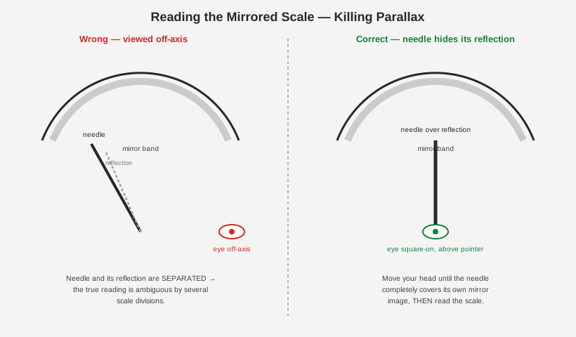
The technique, in one sentence: move your head (not the meter) until the needle visually covers its own reflection in the mirror band, and only then read the number the needle sits over. Any viewing angle where you can see daylight between the needle and its reflection is an angle where you’ll misread the scale by some number of divisions — how many depends on how far off-axis you are and how far the pointer tip sits from the mirror band. On the earlier non-mirrored series (pre-4M, and any 4M/5M/6M/7M unit sold without the “M” mirror option), there is no such self-check available — the only defense against parallax is disciplined dead-on viewing, which is precisely the problem the mirror was introduced to solve.
3.10.2 The cascaded V/mA scales
Above the ohms arc, the 260 dial carries several linear arcs sharing the same pointer travel — a 0–50, a 0–10, sometimes a 0–250 or similar, printed one above another. These are not separate movements; they are the same 50 µA-at-full-scale pointer sweep, re-labeled for each range’s own full-scale value. Reading one of these scales is a two-step act: first note which arc corresponds to the RANGE switch’s current position (the panel range legend and the scale’s own printed full-scale number should agree — e.g., a 0–1000 V range reads off the “0–10” arc with the decimal point moved two places, or off a dedicated 0–1000 arc, depending on the specific scale-plate layout), then read the pointer position against that arc alone, ignoring the others.
This is the reason a 260’s face looks intimidating to a first-time user and is completely mechanical once internalized: the pointer never lies about its own physical angle — the ambiguity is entirely in knowing which printed arc that angle should be read against, which is simply “whatever arc matches the RANGE switch’s numeral.” Vol 4’s operating-procedure volume works through this selection process as part of the step-by-step measurement recipes.
3.10.3 The reversed, non-linear OHMS scale
The ohms arc is printed backward relative to every other scale on the dial: 0 Ω sits at the right-hand end (full pointer deflection) and ∞ (infinite resistance) sits at the left-hand end (zero deflection, no current flowing). This is the direct, inevitable consequence of how the ohms circuit works: more resistance in the unknown under test means less current flows through the movement (recall §7 — the meter’s own battery pushes current through both its internal resistance and the external unknown in series), so a higher unknown resistance produces a smaller deflection, the opposite sense from every voltage or current range, where a bigger input produces a bigger deflection.
The scale is also strongly non-linear — the spacing between, say, “10 Ω” and “20 Ω” near the right-hand (low-resistance) end of the arc is much wider than the spacing between “10 kΩ” and “20 kΩ” crowded near the left-hand (high-resistance) end. This non-linearity is exactly why §6.3’s center-scale readings (12 Ω / 1,200 Ω / 120,000 Ω) matter so much in practice: the scale is most legible — divisions most widely and evenly spaced — near its middle, and increasingly compressed and hard to read precisely as you approach either end. Reading a resistance pinned near the left (very high Ω, small deflection) or jammed against the right (very low Ω, near-full deflection) is both imprecise and a cue to switch ranges rather than trust the number.
3.10.4 The dB scale
The dB arc is a third distinct printing convention: it runs linearly in decibels, which — because dB is itself a logarithmic function of the underlying AC voltage — means the dB arc is compressed relative to the linear AC-volts arcs it shares dial space with, spreading a wide dynamic range of actual signal levels across a single scale run. As with the ordinary AC-volts function, treat dB readings as accurate against a sine-wave source referenced to 600 Ω (§8.2); reading dB off a non-sinusoidal or arbitrarily-terminated signal is a convenience approximation, not a calibrated measurement.
3.11 Full range set — Series 8 / 8P
The complete Table 1-1 range set, reproduced in full as the reference table for this volume:
Table 8 — The complete Table 1-1 range set, reproduced in full as the reference table for this volume
| Function | Ranges | Accuracy | Sensitivity / notes |
|---|---|---|---|
| DC Volts | 0-1-2.5-10-25-50-250-500-1000 V | 2% of full scale | 20,000 Ω/V |
| DC Millivolts | 0-250 mV | 2% of FS | 20,000 Ω/V |
| AC Volts | 0-2.5-10-25-50-250-500-1000 V | 3% of FS | 5,000 Ω/V; responds to average, calibrated to RMS of a pure sine; freq. ref. 100 Hz |
| Output Voltage (AC) | 0-2.5-10-25-50-250 | — | AC component only; limited to 350 VDC blocking |
| DC Microamperes | 0-50 µA | 1.5% of FS | 250 mV drop |
| DC Milliamperes | 0-1-10-100-500 mA | 2% of FS | drop ≈ 250 / 255 / 300 / 500 mV |
| DC Amperes | 0-10 A | 2% of FS | ≈255 mV drop; NOT internally fused |
| Decibels | −20 to +10, −8 to +22, 0 to +30, +6 to +36, +20 to +50 dB | — | 0 dB = 1 mW into 600 Ω |
Table 9 — 10. Full range set — Series 8 / 8P
| Resistance | R × 1 | R × 100 | R × 10,000 |
|---|---|---|---|
| Range | 0–2,000 Ω | 0–200,000 Ω | 0–20 MΩ |
| Center (mid-scale) reading | 12 Ω | 1,200 Ω | 120,000 Ω |
| Nominal open-circuit voltage | 1.5 V | 1.5 V | 9 V |
| Nominal short-circuit current | 125 mA | 1.25 mA | 75 µA |
| Arc accuracy | 2.5° | 2° | 2° |
[CONFIRMED — primary, 260-8/8P Table 1-1. All specs are accuracy as calibrated with the instrument horizontal, its calibrated reference position — see Vol 4 §“Setup” and Vol 5 §“Zeroing & calibration.”]
Beyond the front-panel functions above, the internal architecture surfaced by this volume:
3.12 Putting it together — one movement, six functions
It’s worth closing this volume by stating plainly what all ten preceding sections add up to, because the 260’s dial is intimidating precisely because this unifying fact isn’t visible from the front panel: there is exactly one moving part that ever indicates anything, and every function on the RANGE and Function switches is just a different piece of passive network standing between the input jacks and that one 50 µA coil.
Table 10 — 11. Putting it together — one movement, six functions
| Function | What’s between the jacks and the movement | Governing relationship |
|---|---|---|
| DC Volts | series-multiplier resistor ladder (§3) | $R_{total} = V_{FS} \times 20{,}000\ \Omega/\text{V}$ |
| DC mA / µA / A | Ayrton ring shunt (§4) | shunt ratio sets the fraction of input current reaching the coil |
| AC Volts | multiplier + rectifier, feeding the coil as pulsating DC (§5) | average-responding, RMS-of-sine calibrated |
| Ohms | internal battery (1.5 V or 9 V) + ZERO OHMS pot, external unknown in the loop (§6) | deflection ∝ 1 / (unknown + internal R) |
| Output | AC path + 350 VDC blocking capacitor (§8.1) | reads AC component only |
| dB | AC path, log-scaled against 0.775 V / 600 Ω (§8.2) | $\text{dB} = 20\log_{10}(V/0.775\text{ V})$ |
Two protection layers (§7 — passive diode clamp always, fuses on every series-6-on unit, a resettable relay on “P” models) sit across or in series with all of the above, transparent to a working measurement and only doing anything at all during a fault. And one purely optical feature — the mirror (§1.3, §9.1) — changes nothing electrically and exists solely so the one pointer this whole system shares can be read without ambiguity.
Vol 4 picks up from here as the operator’s-eye view of the same architecture: which switch position to select for a given measurement, the zero-ohms-as-battery-test step in daily use, and the safety practices that follow directly from the circuit behavior described in this volume (why the 10 A range’s lack of a fuse is a live-circuit hazard, why the Output jack’s 350 VDC blocking-capacitor rating is a hard ceiling, why ohms should never be measured on an energized circuit given the meter’s own battery is already driving current through the node). Vol 5 picks up the same architecture from the repair bench, including the exact battery-holder hardware described in §6.2 that Jeff serviced on his 6P.
Sources
- Simpson 260 Series 8 Instruction Manual (PDF, primary — Table 1-1, movement, voltmeter/current/ohms theory, protection): https://simpsonelectric.com/wp-content/uploads/File/260-8man.pdf
- Simpson 260 Series 8P Instruction Manual (PDF, primary — electronic overload protection, Table 1-1/1-2, decibels, fuse part numbers): https://simpsonelectric.com/wp-content/uploads/File/260-8Pman.pdf
- simpson260.com — Series 1 (no taut band, no trimpots): https://www.simpson260.com/260-1/simpson_260-1a.htm
- simpson260.com — Series 4M / 5M (mirror and taut-band debuts): https://www.simpson260.com/260-4/simpson_260-4m.htm , https://www.simpson260.com/260-5/simpson_260-5m.htm
- simpson260.com — Series 6 (taut band standard, battery combo): https://www.simpson260.com/260-6/simpson_260-6.htm
- simpson260.com — Series 8 (mirror standard, 0-25V range): https://www.simpson260.com/260-8/simpson_260-8.htm
- radiomuseum.org — Series 5M (1969), 5P (1968): https://www.radiomuseum.org/r/simpson_volt_ohm_milliammeter_260_series_5m.html , https://www.radiomuseum.org/r/simpson_vom_260_5p.html
- radiomuseum.org — Series 8P (diode + relay protection): https://www.radiomuseum.org/r/simpson_multimeter_260_series_8p.html
- Early 260 operator’s manual voltmeter-circuit theory (copper-oxide rectifier, 20,000 Ω/V derivation), ManualsLib page 11: https://www.manualslib.com/manual/1385338/Simpson-260.html?page=11
- Germanium-diode rectifier substitutes (secondary/forum): https://antiqueradios.com/forums/viewtopic.php?t=183560
- Simpson 260 “Series 3 to 6” repair instructions (multiplier/resistor tables — not machine-readable in this pass, flagged for follow-up): https://www.simpson260.com/downloads/simpson_260-3_to_6_repair_instructions.pdf
- LOC 1955 Simpson Model 260 manual: https://lcweb2.loc.gov/master/mbrs/recording_preservation/manuals/Simpson%20Model%20260%20Volt-Ohm-Milliammeter.pdf