Simpson Model 311-2 VTVM · Volume 1
Simpson 311-2 — Vol 1: Overview — What a VTVM Is & Why It Still Earns Bench Space
A 22 MΩ tube bridge, a needle that shows you which way things are moving, and the honest reason it still sits next to a modern DMM.
1.1 Why a VTVM still earns bench space
Set a modern autoranging DMM next to a Simpson 311-2 and the DMM wins almost every spec on the datasheet — better basic DC accuracy, a display you can read at a glance, no line cord, no warm-up. So why does a 60-year-old tube instrument stay on the bench instead of in a parts bin? Because on one specific, common class of tube-circuit measurement, the VTVM’s whole design exists to solve a problem a general-purpose meter doesn’t prioritize: not disturbing the circuit while you measure it.
- High input impedance is the entire reason this instrument exists. The Simpson 311-2 presents 22 MΩ on every DC range to whatever it’s clipped across (Simpson doubled the industry-typical ~11 MΩ figure other VTVMs of the era used — see the callout below). A tube’s control grid, an AVC (automatic volume control) line, a screen-grid dropping-resistor node, a high-value bias divider — these are all points in a circuit where the actual impedance looking back into the node can run into the hundreds of kΩ to several MΩ. Bridge a meter across a node like that and the meter’s own input resistance forms a voltage divider with the circuit’s source resistance. A meter with a low enough input resistance doesn’t read the voltage that’s there — it reads the voltage that’s there after being crushed by the meter itself. See “The loading problem, worked” below for the actual arithmetic.
- A 20,000 Ω/V VOM — the Simpson 260 sitting on the same bench — is exactly the wrong tool for those same nodes. 20 kΩ/V sounds respectable until you do the multiplication: on the 260’s 250 V DC range that’s only 5 MΩ, and on a lower range it’s proportionally less. Against a divider node whose own Thévenin resistance is 1 MΩ or more, that’s enough loading to give you a confidently wrong number — not a meter that reads “a little low,” a meter that lies smoothly and repeatably. The VTVM and the loadable VOM are not competing designs; they’re tools for two different classes of node, and knowing which node you’re on is half of using either one correctly (see “VTVM vs. VOM vs. modern DMM,” below, and Vol 4 for probing technique).
- The needle earns its keep on rate-of-change work. Peaking an IF transformer, nulling a discriminator, walking a bias trimmer toward a null on the 311-2’s zero-center (“D.C. Galvanometer”) mode — these are jobs where you’re watching which way a reading is moving and how fast, not just reading a static number. A sweeping needle makes overshoot obvious the instant it happens; a digital display flickering through two or three changing digits does not give your hand the same reflex to stop turning the screwdriver. This is standard analog-meter reasoning (the Simpson 260 dive, Vol 1, makes the same case for the VOM side) — it applies just as much here, and the 311-2’s zero-center mode exists specifically to support it.
- It needs no logic, just warm-up. There’s no menu, no auto-ranging algorithm deciding what it thinks you meant, no firmware to glitch near a transmitter or a switching supply. Turn the function switch off OFF and it’s off; there is a genuine one-hour warm-up for the tube bridge to settle thermally (Vol 4 §“Operating procedure” covers the practical routine), but once it’s warm and re-zeroed on the current range and function, the reading is the reading — an analog voltage imbalance across a bridge, not a computed result.
Note — this cuts both ways. A 22 MΩ input is wonderful for not loading a high-Z node, but that same high impedance means an ungrounded or loosely-clipped probe lead can pick up stray 60 Hz hum and capacitively-coupled “phantom” voltage from nearby live wiring far more readily than a low-Z VOM would. A VOM’s low input resistance quietly bleeds that phantom signal to near-zero; a VTVM’s high input resistance does not. Good grounding and lead discipline matter more on this instrument, not less — see Vol 4.
1.1.1 The loading problem, worked
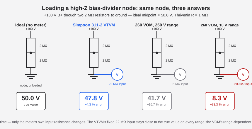
It’s easy to leave “high input impedance matters” as an abstraction. Here is the arithmetic for a representative high-Z node — say a symmetric bias divider off a +100 V B+ supply, two 2 MΩ resistors in series to ground, tapped at the midpoint. With nothing connected, that node sits at an ideal 50.0 V (a straight 2 MΩ : 2 MΩ split); looking back into the node from the test point, its own Thévenin resistance is the two 2 MΩ legs in parallel — 1 MΩ.
Table 1 — The loading problem, worked
| Meter clipped on | Meter’s DC input resistance | Reading at the node | Error vs. the true 50.0 V |
|---|---|---|---|
| (nothing — ideal) | ∞ | 50.0 V | — |
| Simpson 311-2 VTVM | 22 MΩ (all ranges) | 47.8 V | −4.3 % |
| Simpson 260 VOM, 20 kΩ/V, 250 V range | 5 MΩ | 41.7 V | −16.7 % |
| Simpson 260 VOM, 20 kΩ/V, 10 V range | 200 kΩ | 8.3 V | −83.3 % |
That bottom row is not a contrived worst case — it’s what happens the moment someone reflexively drops a VOM to a lower range to “get more resolution” on a node whose own source resistance is high. The VOM doesn’t fail loudly; it just reports a plausible, wrong voltage with total confidence. The VTVM’s loading error against the same node is −4.3 %, dramatically smaller than the VOM’s −16.7 % or −83.3 % — which is the entire point of paying for 22 MΩ in the first place. That loading error is a separate error source from the instrument’s own rated accuracy (±3 % of full scale, DC — Vol 4 §“Accuracy and reading technique”); it adds to the spec rather than being bounded by it, so a careful reading of this node still carries roughly a −4.3 % loading error on top of whatever the meter’s own ±3 % FS accuracy contributes.
1.2 What this unit is: the Simpson 311-2
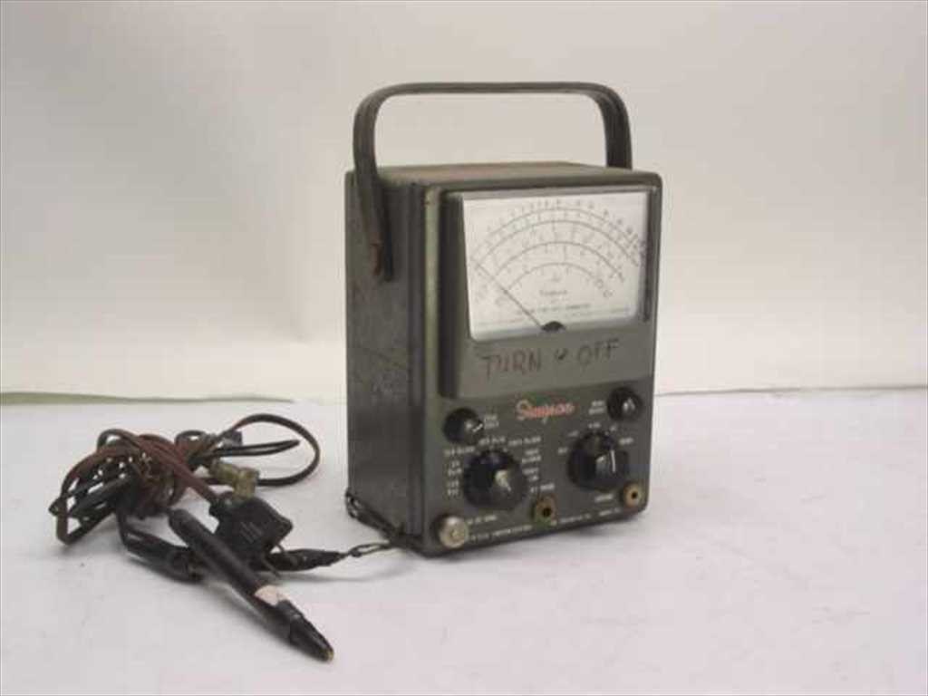
The Simpson Model 311-2 is a mid-1960s all-tube vacuum-tube voltmeter built by the Simpson Electric Company of Chicago, Illinois — the second revision (the printed-circuit-board revision) in a compact-portable VTVM line that runs 311 → 311-1/311-2 → 311-3, sitting below Simpson’s larger bench-style 312 and above the earlier 303. It is a genuine successor design, not a rebadge: the original Model 311 shipped an Operator’s Manual dated © 1958 (this printing reprinted January 1962), and the 311-2’s manual is dated © 1966, describing the same electrical design re-engineered onto a printed-circuit board. Production of the line as a whole runs from roughly 1958 into the early 1970s, overlapping the industry’s slow transition to solid-state instruments.
⚠ Two corrections worth stating up front, because they contradict what a lot of secondary sources repeat about VTVMs of this general type:
- DC input resistance is 22 MΩ on every range — not the ~11 MΩ figure common to other VTVMs of the era (RCA’s WV-98, EICO’s, Heathkit’s designs all land near 11 MΩ — one 1 MΩ probe-tip isolating resistor plus a roughly 10 MΩ input divider, the industry-standard arrangement). Simpson’s own manuals state it twice, in nearly identical language, for both the 311 and the 311-2: “Input resistance is 22 megohms for all ranges.” Simpson built a noticeably larger divider network to get there. Do not round this down to 11 MΩ.
- There is no FET-input Simpson 311. The 311 line stayed all-tube through the 311-2 and the later 311-3. Simpson’s solid-state, FET-input successor is a genuinely different instrument with a different model number — the Model 313 “Solid-State VOM.” If you see a 311 described as FET-input anywhere, that’s a conflation with the 313, not a late-production 311 variant.
1.2.1 The active front end — two tubes, one job each
The 311-2’s entire measuring path runs through exactly two vacuum tubes, and each has one clearly defined job. There is no 12AX7 anywhere in this instrument — an easy mix-up, since the 12AX7 is a common companion part in other tube gear of the era, but Simpson’s own parts list and tube-replacement section for the 311-2 name only these two:
Table 2 — section for the 311-2 name only these two
| Reference | Tube type | Function |
|---|---|---|
| V2 | 12AU7 (dual triode) | The balanced-bridge DC amplifier. Both triode halves form the two arms of a DC bridge; the meter movement sits across the bridge and reads the imbalance. This tube does the actual measuring for every function — DC, AC (after rectification), and ohms all ultimately deflect the meter through this bridge. |
| V1 | 6AL5 (dual diode) | The peak-to-peak AC rectifier. On the AC and ohms-irrelevant AC-only path, it converts the incoming AC signal into a proportional DC voltage (voltage-doubler / peak-to-peak topology) that the 12AU7 bridge then measures like any other DC input. It is the rectifier, not “the bridge” — a mislabel worth guarding against. |
A third, non-measuring rectifier lives in the power supply, not the signal path: CR-1, a silicon diode off the power transformer, supplies the instrument’s own B+ and heater rails. It’s the one semiconductor in an otherwise all-tube instrument, and it doesn’t touch the measurement itself. (Vol 2 covers the complete bridge and rectifier theory in detail; Vol 3 covers where each part physically lives on the 311-2’s PCB.)
Note — if the accessory RF probe (Simpson part 0731 on the 311, 0174 on the 311-2) is plugged in, a fully-equipped instrument effectively has three tubes on the bench — the probe carries its own 6AL5 in the handle, rectifying the high-frequency signal right at the test point before it travels down the cable. Vol 4 covers the probe kit.
1.2.2 Headline specifications
Table 3 — Headline specifications
| Parameter | Value | Confidence |
|---|---|---|
| Tube complement | 12AU7 (balanced-bridge DC amplifier) + 6AL5 (peak-to-peak AC rectifier); silicon diode CR-1 in the power supply | Confirmed — Simpson 311-2 manual |
| DC input resistance | 22 MΩ, all ranges | Confirmed — both manuals |
| AC input resistance | 2.2 MΩ minimum at 60 Hz | Confirmed — both manuals |
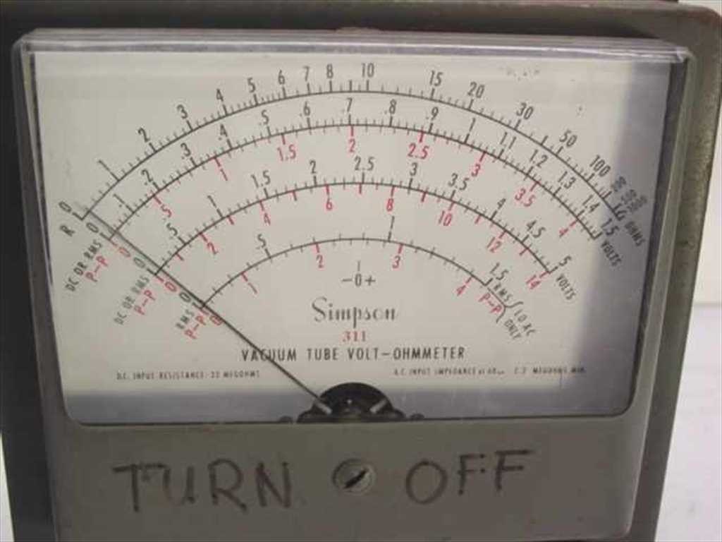
| DC voltage ranges | 1.5 / 5 / 15 / 50 / 150 / 500 / 1500 V full scale (7 ranges); to 30,000 V with the HV probe | Confirmed |
| AC voltage ranges (RMS, black arcs) | 1.5 / 5 / 15 / 50 / 150 / 500 / 1500 V RMS, sine waves only | Confirmed |
| AC voltage ranges (peak-to-peak, red arcs) | 311-2: 4 / 14 / 40 / 140 / 400 / 1400 / 4000 V p-p, any waveform | Confirmed |
| Ohms ranges | ×1 (10 Ω center) through ×1M (10 MΩ center), 6–7 decade ranges depending on printing | Confirmed for the 311; the 311-2 manual’s table has an internal inconsistency — see Vol 3 |
| DC accuracy | ±3 % of full scale | Confirmed |
| AC accuracy | ±5 % of full scale | Confirmed |
| Ohms accuracy | ±3° of arc | Confirmed |
| Meter movement | Custom Simpson D’Arsonval, ~200 µA full scale, ~1,000 Ω internal resistance | Likely — secondary-sourced figures, but the movement part number (15-AC2311-2) is model-specific, confirming it’s a custom Simpson movement |
| Ohms battery | One 1.5 V “C”-cell dry cell (internal) | Confirmed |
| Power | 105–125 V AC, 50/60 Hz, 5 W | Confirmed |
| Case | 7½ in H × 5⅝ in W × 4½ in D; 4½ lb net, 6 lb shipping | Confirmed |
| dB scale | Not documented — no dB arc appears in either manual’s scale description | Not found — do not assume one is present |
1.2.3 Identity, lineage & dating
Simpson Electric Company built the 311 line at its Chicago plants (Lake Street and Kinzie Street) and at Lac du Flambeau, Wisconsin and Aurora, Illinois, with a Canadian arm, Bach-Simpson Ltd. of London, Ontario, handling that market. The compact-portable VTVM line this dive covers sits in a larger Simpson VTVM family: the earlier Model 303 (introduced roughly 1957, ~$68 with probes new) came first, then the 311 → 311-1 → 311-2 → 311-3 progression this dive is about, with the larger bench-style Model 312 (© circa 1966, a 190 mm scale, the same 6AL5 + 12AU7 tube pairing in a bigger cabinet) as a contemporary sibling rather than a strict successor. Simpson’s eventual solid-state, FET-input VOM — the Model 313 — replaced none of these directly; it’s a different instrument family, not a “311-4.”
Table 4 — Identity, lineage & dating
| Model | Manual date | What changed |
|---|---|---|
| 303 | ~1957 (secondary-sourced) | Earlier Simpson VTVM, predates the 311 line |
| 311 (original, also labeled “311-1” on one scan archive) | © 1958, this printing reprinted “1-62” (Jan. 1962) | Baseline all-tube design; AC bandwidth to 100 kHz |
| 311-2 | © 1966 (part 5-110700) | Same electrical design re-engineered onto a printed-circuit board; AC bandwidth widened to ~1 MHz on the lower ranges; RF probe upgraded to 250 MHz (part 0174) |
| 311-3 | Later 1960s (“from the 60’s” per period listings) | Exists and is field-repairable; no primary manual read for this dive — treat 311-3-specific details as unverified until one surfaces |
A couple of dates in the record are genuinely muddy, and it’s worth flagging rather than smoothing over: one secondary source (Nuts & Volts’ “Vintage Tek” column) dates the 311 to “circa early 1950s,” which conflicts with the 1958 copyright printed on the primary manual itself — the manual’s own date is the one to trust. And no original list price for the 311 or 311-2 turned up in the primary catalogs consulted for this dive; today’s used-market price runs around $35, for scale against the 303’s ~$68 new price a decade earlier. None of this uncertainty touches the electrical specs above — those come directly off Simpson’s own manual text, twice, in nearly identical wording across both revisions.
⚠ Danger — the 311-2’s metal case is tied to the third-wire safety ground of its own line cord — standard and correct practice — but Simpson’s own manual specifically warns to exercise care when a measurement is taken relative to line voltage, since the chassis carries line-ground potential. Treat it like any other mains-powered bench instrument: no floating the case, no defeating the ground pin. Full bench-safety discipline (one-hand rule above ~50 V, HV-probe handling to 30 kV, hazardous materials in period gear) is in
_shared/legal_ethics.md.
1.3 The two-VTVM cross-check bench
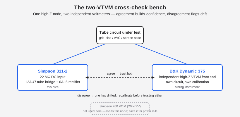
Jeff keeps the Simpson 311-2 next to a B&K Dynamic 375 VTVM as a deliberate pair, not a redundant spare. The reasoning is simple: any single voltmeter can drift out of calibration quietly, and a drifting VTVM doesn’t announce itself — it just reads a number, and the number looks exactly as authoritative as a correct one would. Two independently-calibrated instruments of the same class, clipped to the same node, either agree (high confidence in both) or disagree (one of them needs attention before you trust either reading again).
The two instruments are close enough in role to make the comparison meaningful — both are line-powered, warm-up-dependent, high-input-Z VTVMs meant for exactly the tube-circuit nodes a VOM would load — while being different enough in implementation to make an agreement genuinely reassuring rather than two instruments sharing one hidden flaw. The Simpson is the tube-bridge design covered in this dive: 22 MΩ DC input, a 12AU7 balanced bridge, a 6AL5 rectifier. The B&K 375 is a later “Dynamic”-series VTVM from the same general era with its own front end and its own DC input figure — its own deep dive (not yet authored to the same verification standard as this one) is the place to cite its exact circuit and specs; treat any number for it here as provisional until that dive exists. What matters for this section is the role: a second, independently-built high-Z voltmeter to check the first one against, both warmed up and re-zeroed before comparison.
Note — neither VTVM belongs on the bench instead of the Simpson 260 VOM. The 260 is the right instrument for power rails, current measurement, and the ohms-driven diode/transistor/capacitor go/no-go tests its internal battery current makes possible (its own Vol 1 covers that ground). The two-VTVM bench exists specifically for the subset of nodes where the 260’s 20 kΩ/V loading would give a wrong answer — see the table above.
1.4 VTVM vs. VOM vs. modern DMM — when to reach for which
None of these three instrument classes is strictly “better” — each optimizes for a different measurement situation, and knowing which one to reach for before you clip a lead on is most of doing this kind of bench work correctly.
Table 5 — VTVM vs. VOM vs. modern DMM — when to reach for which
| VTVM (Simpson 311-2) | VOM (Simpson 260) | Modern DMM | |
|---|---|---|---|
| DC input impedance | 22 MΩ, fixed on every range | 20 kΩ/V — varies with the range selected (e.g. 5 MΩ on a 250 V range, 200 kΩ on a 10 V range) | ~10 MΩ, fixed on every range (typical, not Simpson-specific) |
| AC input impedance | 2.2 MΩ minimum | 5 kΩ/V — also range-dependent | ~10 MΩ, fixed, typically shunted by input capacitance |
| Power required | Mains (105–125 V AC) for the tube bridge; needs warm-up | None for volts/current — the movement is passive; internal battery powers ohms only | Internal battery (9 V or coin cell); instant-on |
| Readout | Analog needle, multi-arc scale, scale math (range × arc position) | Analog needle, mirrored scale to kill parallax, scale math | Digital display, auto-ranging, no scale math |
| Best for | Grid-bias, AVC, screen-supply, and any node whose own source resistance is high enough that a VOM would load it — see the worked example above | Power rails, current measurement, quick ohms-driven diode/transistor/cap go/no-go checks, work where instant-on and no line cord matter | General precision work, data logging, auto-ranging convenience, min/max/hold functions, CAT-rated safety on live circuits |
| Rate-of-change / null work | Excellent — the needle plus the zero-center galvanometer mode is built for peaking and nulling | Excellent — same needle-inertia argument | Weak — digits flicker rather than sweep; some DMMs add an analog bar-graph specifically to compensate |
| Susceptibility to induced/phantom voltage | High — the same high input Z that avoids loading also picks up stray coupling readily; good grounding technique matters | Low — the low input Z bleeds phantom pickup toward zero, which is itself a useful diagnostic (see the Simpson 260 dive, Vol 1) | High — a fixed ~10 MΩ input behaves similarly to a VTVM here, though many DMMs add a low-Z “LoZ” mode specifically to reject it |
| Notable weaknesses | Warm-up required; re-zero on every range/function change (Vol 4); no dB scale documented on this model; tube-life and battery-life maintenance | Loads high-Z nodes badly (see the worked example above); mirror-scale reading takes practice | No needle feel for rate-of-change; some models’ “10 MΩ” input can still shift on certain ranges — check the datasheet, don’t assume |
Practical rule of thumb: if you don’t know the source resistance of the node you’re about to probe, reach for the VTVM first. A VTVM reading a genuinely low-Z power rail is still accurate — the 22 MΩ input simply barely loads a low-Z node either way — but a VOM reading a genuinely high-Z node can be badly wrong, and it will not tell you so. The failure mode only runs one direction, which is why the VTVM is the conservative default for unfamiliar tube circuitry, and the VOM is the deliberate choice once you know the node is a power rail, a current path, or a component you want to go/no-go test on ohms.
1.5 Where this dive goes from here
This volume is the orientation. The rest of the Simpson 311-2 dive works from theory outward to the physical bench:
- Vol 2 — How a VTVM Works: The Balanced Bridge, Rectifier & Ohms Circuit. The 12AU7 balanced-bridge DC amplifier in detail — how two triode halves sharing one envelope and one heater supply give a stable, self-cancelling zero; the 6AL5’s peak-to-peak rectification and why the black RMS arcs and red peak-to-peak arcs mean genuinely different things on non-sine waveforms; the internal 1.5 V “C”-cell ohms circuit and how OHMS ADJUST compensates for battery aging.
- Vol 3 — Inside This Unit: Hardware, Controls & Ranges. The four front-panel controls (RANGE, function switch, ZERO ADJUST, OHMS ADJUST), the complete DC/AC/ohms range tables including the 311 vs. 311-2 discrepancies noted above, the PCB layout, and the standard AC-DC-OHMS probe with its slide-switch DC isolating resistor.
- Vol 4 — Using It: Operating Procedure, Probes & Safety. Warm-up and zeroing procedure step by step, the accessory RF probe (Simpson part 0731 on the 311 / 0174 on the 311-2, to 100 MHz and 250 MHz respectively) and DC high-voltage probe (part 0732, ×100, to 30 kV — with the discrepancy between its 50,000 V full-scale marking and the 30,000 V safe operating limit), reading technique on the multi-arc scale, and the mains-ground safety point flagged above.
- Vol 5 — Calibration & Refurbishing. The factory six-step calibration procedure (R29 ZERO SET, R32 AC contact-potential, R20 DC CAL, R21 AC CAL), the 48-hour tube-aging requirement after a 12AU7 replacement, precision-resistor drift in the 22 MΩ divider chain, and the classic corroded battery-holder failure.
- Vol 6 — Cheatsheet & the Two-VTVM Bench. A one-page quick reference (ranges, accuracy, probe specs, common fault symptoms) plus the full comparison writeup for the 311-2/B&K 375 pairing introduced above.
Sources
Primary (Simpson Electric Company operator’s manuals, read in full):
- Simpson Electric Co., Operator’s Manual — Vacuum Tube Voltmeter Model 311-2, © 1966 (part 5-110700). https://www.simpson260.com/downloads/simpson_311-2_user_manual.pdf
- Simpson Electric Co., Operator’s Manual — Vacuum Tube Voltmeter Model 311, © 1958 (printing 1-62-JM-BL-Rev. 1). https://simpson260.com/downloads/simpson_311-1_user_manual.pdf
- Simpson 311-2 manual mirror: https://archive.org/details/Simpson_311-2_VTVM
- Manual index (BAMA): https://bama.edebris.com/manuals/simpson/311-2
Secondary / corroboration:
- Nuts & Volts, “Vintage Tek: The Vacuum Tube Voltmeter” — https://www.nutsvolts.com/magazine/article/vintage-tek-the-vacuum-tube-voltmeter
- Radiomuseum — Simpson VTVM 312 and Simpson 303: https://www.radiomuseum.org/r/simpson_vacuum_tube_volt_ohmmete.html ; https://www.radiomuseum.org/r/simpson_vacuum_tube_voltmeter_303.html
- Simpson 313 Solid-State (FET) VOM — ManualsLib product page: https://www.manualslib.com/products/Simpson-313-Solid-State-Vom-14060996.html
- Antique Radio Forums, “Simpson 311 VTVM” and “Simpson 311-3 VTVM, troubleshooting”: https://antiqueradios.com/forums/viewtopic.php?t=329645 ; https://antiqueradios.com/forums/viewtopic.php?t=84636
- Recycled Goods, Simpson 311 listing (photos, used-market price): https://recycledgoods.com/simpson-311-vacuum-tube-volt-ohmmeter/
- Reverb, Simpson 311-3 listing (“from the 60’s” dating): https://reverb.com/item/6845420-simpson-311-3-vacuum-tube-volt-ohmmeter-from-the-60-s