Simpson Model 311-2 VTVM · Volume 2
Simpson 311-2 — Vol 2: How a VTVM Works — The Balanced Bridge, Rectifier & Ohms Circuit
One 12AU7 bridge, one 6AL5 rectifier, one C-cell, and a 22 MΩ divider — every function on the 311-2 reduces to the same idea: put a tube grid, not a coil, across the unknown.
2.1 Why a VTVM at All — the Grid Instead of the Coil
Every analog VOM — a Simpson 260 included — measures current. A moving-coil meter is a milliammeter or microammeter at heart; a “voltmeter” range is just that meter with a series multiplier resistor added, so that reading a voltage necessarily means drawing a small current from the circuit under test. On a 20 kΩ/V VOM, the 2.5 V range presents only 2.5 V × 20 kΩ/V = 50 kΩ to the circuit. Across a tube-circuit grid-leak resistor of 1 MΩ or more, that 50 kΩ is a serious load — it pulls the node down and you measure the meter’s loading, not the circuit’s real operating point. This is exactly the failure mode covered for the Simpson 260 VOM in its own dive; see the Simpson 260 VOM subproject for the loading arithmetic worked in full.
A vacuum-tube voltmeter sidesteps the problem by measuring voltage with a voltage-controlled device instead of a current-summing one. The unknown voltage is applied to the control grid of a triode. A grid biased negative with respect to its cathode (the normal operating condition here) does not conduct — the grid-to-cathode “input” looks, to first order, like an open circuit. No conduction path means no current is drawn from the node under test to make the measurement; the grid only needs enough current to charge its own tiny input capacitance, which for DC settles to a leakage-only picture. The tube’s plate current does change in response to the grid voltage — that’s how the reading gets out — but that plate-current change happens inside the tube, powered by the instrument’s own B+ supply, not by current stolen from the circuit under test.
That’s the whole idea in one sentence: a VTVM converts “measure this voltage” into “unbalance this amplifier,” and the amplifier’s own power supply — not the circuit under test — supplies the energy to move the pointer. Everything below is the Simpson 311-2’s specific implementation of that idea: a real, finite (not infinite) series isolating resistor at the probe tip, a real divider network setting the actual input impedance, a real balanced-bridge amplifier stage built from one 12AU7 dual triode, a real AC rectifier built from one 6AL5 dual diode, and a real ohms circuit built around a 1.5 V dry cell. None of these are unique to Simpson — every classic tube-era VTVM (RCA WV-98, EICO 232, Heathkit V-7A, and this instrument’s own bench-mate, the B&K Dynamic 375) uses the same family of building blocks. What differs from make to make is component values, and Simpson’s divider is the standout: it is built to twice the usual input resistance. That’s the story of the next section.
2.1.1 “~No Current,” Not “No Current” — What Actually Limits a Grid’s Input
It’s worth being precise about the phrase “draws essentially no current,” because a real triode grid is not a literal open circuit, and understanding why it’s close to one explains why the 311-2’s designers still bothered with a 22 MΩ divider instead of, say, a 1,000 MΩ one. In normal operation the 12AU7’s measuring grid is biased negative with respect to its cathode — that’s the whole point of Class A triode operation — and a negatively-biased grid, by design, repels the cathode’s thermionically-emitted electron cloud rather than collecting it. That’s the dominant reason grid current is small: there’s no forward conduction path for electrons to flow into the grid the way current flows into the base of a forward-biased transistor junction.
“Small” is not “zero,” though. Three secondary mechanisms still move a little current across a real grid-cathode gap: leakage across the tube’s internal insulation and along the socket/wiring, positive-ion current from residual gas inside the envelope being attracted to the negative grid, and — at high enough grid temperatures, generally not an issue at the modest dissipations here — a trickle of grid thermionic emission in the reverse direction. All three are small enough, in a healthy tube, to be swamped by the input signal current flowing through even a modest divider resistance; that’s why 22 MΩ (rather than 220 MΩ or 2,200 MΩ) is “enough” — the goal isn’t literally zero current, it’s current small enough that the 22 MΩ divider’s own voltage drop from that leakage is negligible next to the voltage being measured. Push the divider resistance far higher and a different problem appears: any residual grid current (plus ordinary circuit-board leakage across humidity and dust) becomes a larger fraction of a smaller total current budget, actually degrading accuracy rather than improving it, while the input capacitance charging through a larger resistance also slows the meter’s settling time. Twenty-two megohms is Simpson’s chosen balance point between “load the circuit as little as reasonably possible” and “keep leakage-driven error and settling time under control” — a real engineering tradeoff, not simply “as high as physically achievable.”
Note — This volume is schematic-grade theory: what each stage does and why, redrawn as simplified illustrative diagrams rather than a reproduction of Simpson’s factory schematic. For the as-built component layout, part numbers, and the physical unit, see Vol 3 §2–§4. For the step-by-step operating sequence that puts this theory to work at the bench, see Vol 4.
2.2 The Probe’s Series Isolating Resistor and the 22 MΩ Divider
2.2.1 The Classic 11 MΩ VTVM and Why Simpson Doubled It
The textbook tube-voltmeter front end most technicians of the era learned on — RCA’s WV-98 family, the EICO 232, the Heathkit V-7A — combines a 1 MΩ series isolating resistor built into the DC probe tip with a ~10 MΩ input divider inside the chassis, for a total DC input resistance of roughly 11 MΩ. That combination is common enough that “11 megohms” became the informal industry shorthand for “a VTVM’s input impedance,” and it shows up (uncritically) in a fair amount of secondary literature about VTVMs in general, including at least one article that analyzes the Simpson 311 using that same 11 MΩ figure.
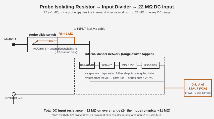
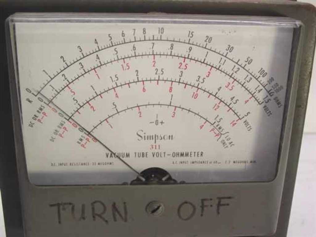
The Simpson 311 and 311-2 do not follow that convention. Both operator’s manuals state, in nearly identical language, that “input resistance is 22 megohms for all ranges” — a figure that shows up printed directly on the meter’s front panel above the dial as “DC INPUT RESISTANCE 22 MEGOHMS” (visible in Figure 1 below). Simpson built a divider network roughly twice the industry-typical value: the 311-2 parts list documents individual divider resistors including R17 (20 MΩ), a set R34–R37 (making up the balance of the 22 MΩ chain across ranges), R15 (5 MΩ), and a group R33/R38/R39 in the 3.5–3.8 MΩ range, tapped by the range switch so that each of the seven DC ranges sees the same 22 MΩ total looking back from the input jack. The probe’s own series isolating resistor (R6, ≈ 1 MΩ ±1 %) is part of that same chain — it lives in the probe body itself, switched in only on the probe’s DC slide-switch position, and adds in series ahead of the internal divider.
Table 1 — The Classic 11 MΩ VTVM and Why Simpson Doubled It
| Path element | Approx. value | Where it lives |
|---|---|---|
| Probe tip series isolating resistor (R6) | ≈ 1 MΩ ±1 % | Inside the AC-DC-OHMS probe handle, switched in on DC only |
| Internal divider network (R17, R34–R37, R15, R33/R38/R39, etc.) | sums to ≈ 21 MΩ | Chassis, range-switch tapped |
| Total DC input resistance, all ranges | 22 MΩ | Printed on the front panel |
| AC input resistance (60 Hz, minimum) | 2.2 MΩ | Same input jack, function switch on AC |
| With the 0732 HV probe fitted | 2,200 MΩ | HV probe adds its own ×100 multiplier resistor in series |
Note — Don’t carry the “11 MΩ” figure over to this instrument. It is correct for a lot of other tube-era VTVMs, but Simpson’s own manuals are explicit and repeated on this point, and the number is printed on the meter itself. The 22 MΩ figure applies to both the 311 and the 311-2 — Simpson did not change it between revisions.
Why did Simpson bother doubling a number that was already “high enough” to beat any VOM? A larger divider means less current is drawn from the node under test for any given DC input, which matters most on the very-high-impedance grid-bias and grid-leak nodes common in tube receivers and audio gear — exactly the circuits this instrument was built to service. It also means the probe’s own loading effect is a smaller fraction of a typical 1–10 MΩ source impedance, so measurements on those nodes read closer to the true undisturbed voltage. The tradeoff is a slightly slower-settling meter (a 22 MΩ source charging the amplifier’s input capacitance takes a beat longer than an 11 MΩ one) — in practice a non-issue on a DC bench measurement where the technician is watching the needle settle anyway.
2.2.2 Loading, Worked: 22 MΩ Against a 20 kΩ/V VOM
The abstract case for “high input impedance” becomes concrete with numbers. Consider a tube receiver’s grid-leak bias node fed through a 1 MΩ resistor from a 100 V B+ rail — a perfectly ordinary tube-circuit source impedance. A voltage divider forms between that 1 MΩ source resistance and whatever resistance the meter itself presents, and the fractional error introduced is simply the meter’s loading resistance compared to the source resistance: error ≈ source R ÷ (source R + meter R).
Table 2 — Loading, Worked: 22 MΩ Against a 20 kΩ/V VOM
| Source resistance (typical tube-circuit node) | Simpson 260 VOM, 20 kΩ/V, on a 10 V range (200 kΩ meter R) | Simpson 311-2 VTVM, 22 MΩ meter R |
|---|---|---|
| 1 MΩ | ≈ 200 kΩ vs. 1 MΩ → reads ~83 % low | 22 MΩ vs. 1 MΩ → reads ~4.3 % low |
| 5 MΩ | 200 kΩ vs. 5 MΩ → reads ~96 % low | 22 MΩ vs. 5 MΩ → reads ~18.5 % low |
| 10 MΩ | 200 kΩ vs. 10 MΩ → reads ~98 % low | 22 MΩ vs. 10 MΩ → reads ~31 % low |
Neither instrument is loading-free at the higher end of that table — even 22 MΩ is not “infinite,” and a genuinely high-impedance node (a grid-leak resistor in the multi-megohm range, or an unbypassed cathode-bias node with a large-value resistor) will still visibly load down against a VTVM, just far less catastrophically than against a VOM. This is the honest version of “a VTVM out-classes a VOM on high-Z nodes”: not immunity to loading, but an order-of-magnitude reduction in it. It’s also why the classic troubleshooting habit of cross-checking a suspiciously “wrong” reading against a second, independently-designed high-impedance meter — exactly the two-VTVM bench discipline this instrument shares with the B&K Dynamic 375, detailed in Vol 6 — catches loading errors that a single meter alone can’t reveal.
Note — The Simpson 260 VOM comparison above uses its 20 kΩ/V sensitivity figure and the DC range’s own multiplier; see the Simpson 260 VOM subproject for that instrument’s full range/loading table. The loading percentages above are simple two-resistor-divider arithmetic (source R and meter R in series), not quoted from either manual — treat them as illustrative engineering arithmetic, not a Simpson-published specification.
2.2.3 Why the Isolating Resistor Exists at All
If the grid draws essentially no current, why put a 1 MΩ resistor in series with it in the first place — doesn’t that just add resistance for no benefit? Two reasons, both standard VTVM design practice and both applicable here. First, the grid together with its lead and the probe’s own shielded cable forms a small capacitance to ground; on its own, that capacitance in combination with a very high-impedance node can ring or oscillate at RF, especially if the probe brushes a live oscillator or RF stage — the series resistor damps that tendency by de-Qing the parasitic LC formed by lead inductance and input capacitance. Second, the same resistor blocks stray RF and hash pickup on the DC lead from reaching the grid and being (mis)rectified there, which would otherwise show up as a bogus DC offset on a supposedly clean DC reading. Both effects are why the resistor is switched in only for DC — on AC and OHMS, where the signal of interest is either already being rectified deliberately (AC) or is a controlled DC from the internal battery (OHMS), the extra isolation isn’t needed and the probe switches straight through.
2.3 The 12AU7 Balanced-Bridge DC Amplifier
2.3.1 Correcting the Record: No 12AX7, and the 6AL5 Is Not “the Bridge”
Two tubes, and only two, do the work of this instrument on every function: a 12AU7 dual triode (Simpson’s V2) and a 6AL5 dual diode (V1). Both the 1958 Model 311 manual and the 1966 Model 311-2 manual name these two parts explicitly in their tube-replacement and parts-list sections, and the 311-2’s own labeling in the parts list — “12AU7 aged,” “6AL5 aged” — leaves no ambiguity about which part does which job. There is no 12AX7 in this instrument on either revision; if a parts list, an eBay listing, or a scaffold note says otherwise, it is wrong. And of the two tubes present, it is the 12AU7 that forms the balanced bridge described in this section — the 6AL5 is the rectifier covered in §4, not “the bridge” itself. Getting these two backward is the single most common error in casual write-ups of this instrument, so it’s worth stating plainly before going further: V2 (12AU7) = bridge amplifier, used on every function; V1 (6AL5) = AC rectifier, used only on AC/RF.
Simpson chose the 12AU7 specifically for this role because it is a low-mu twin triode — its two triode sections have a modest voltage gain per section but very stiff, linear, predictable characteristics, and (critically for a bridge circuit) the two halves of a single 12AU7 envelope are manufactured together and track each other closely as they age and as the tube warms up. A high-gain twin triode like a 12AX7 would amplify more per stage, but its higher plate resistance and greater susceptibility to microphonics and drift work against the goal here, which isn’t raw gain — it’s a stable, repeatable null. That is one plausible reason Simpson favored the lower-gain part; it isn’t a reason documented explicitly in the manuals, so treat it as design-rationale inference rather than a quoted Simpson statement.
2.3.2 How the Bridge Balances
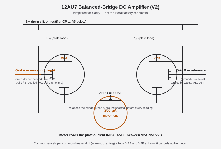
“Balanced bridge” describes the topology, not a literal four-resistor Wheatstone bridge — Simpson’s own manual text uses the word “bridge” for this stage, and it is functionally in the same family as the more commonly described “cathode follower” front end used in some competing designs, just implemented as a differential (push-pull) pair rather than a single-ended follower. The two triode halves of the 12AU7 — call them V2A and V2B — are wired as two arms of the bridge. One half (V2A) has its grid connected, through the isolating resistor and divider network of §2, to the actual test point — this is the “measuring” arm. The other half (V2B) has its grid tied to a stable reference (effectively ground, adjustable through the ZERO ADJUST control) — this is the “reference” arm. The 200 µA meter movement (see Vol 3 §5 for the movement’s own specs) is wired across the bridge, between the two triode halves, so that it reads the difference in plate current between V2A and V2B rather than the absolute plate current of either one alone.
With no signal applied — probe and ground clip shorted together, or simply nothing connected — both grids sit at essentially the same potential, both triode halves conduct essentially the same plate current, and the meter (sitting between two equal currents) reads zero. That’s the state ZERO ADJUST is used to establish: with the input shorted, the front-panel ZERO ADJUST knob is turned until the pointer sits exactly on 0, compensating for any small manufacturing mismatch between the two triode halves, aging, or a shift in supply voltage. Apply a DC voltage to the probe, and V2A’s grid moves relative to V2B’s — V2A’s plate current changes while V2B’s stays fixed at the reference point, the bridge unbalances, and the meter deflects by an amount proportional to the applied grid voltage. Because the whole front end downstream of the isolating resistor and divider is linear over the working range, that deflection tracks the input voltage closely enough to support the specified ±3 % of full scale DC accuracy.
2.3.3 Why the Bridge Is More Stable Than a Single Tube
The whole point of running two triode halves differentially instead of reading one triode’s plate current directly against a fixed reference resistor is common-mode rejection of drift. A single-tube DC amplifier’s plate current depends on heater voltage, B+ supply voltage, tube aging, and ambient temperature — all four wander over the course of a warm-up cycle and over the tube’s service life, and every bit of that wander shows up directly as a phantom shift in the meter reading, indistinguishable from a real input change. Because V2A and V2B share the same 12AU7 envelope — the same heater, warming at the same rate; the same cathode structure, aging together; fed from the same B+ rail, so any supply sag affects both equally — a drift that raises (or lowers) both triodes’ plate current by the same amount leaves the difference between them unchanged, and the meter, which reads only that difference, doesn’t move. Only the differential signal — the actual voltage difference between V2A’s measuring grid and V2B’s reference grid — gets through to the pointer. That common-mode cancellation is precisely why the manuals call this stage a “bridge”: it’s a differential measurement by design, not an accident of layout.
It isn’t perfect cancellation in practice — no two triode halves match exactly, contact potentials differ slightly between the AC and DC signal paths (addressed by an internal trimmer, R32, covered in Vol 5), and long-term component aging on the plate-load resistors can shift the balance point over months of service. That residual imbalance is exactly what ZERO ADJUST is for, and why the manuals’ recommended procedure has the technician re-zero on every range and function change rather than trusting a zero set once at power-up. A 12AU7 that has just been replaced needs Simpson’s specified ≥48-hour aging period, powered up, before it’s trusted for calibration — new tubes exhibit transient characteristic shifts during their first couple of days of operation that would otherwise masquerade as a bad zero or bad calibration. Refurbishing detail on this — and on what a mismatched, gassy, or soft 12AU7 looks like on the bench — is covered fully in Vol 5.
2.3.4 “Bridge” vs “Cathode Follower” — a Terminology Note for the Two-VTVM Bench
Different manufacturers describe functionally similar VTVM front ends with different words, and it’s worth reconciling that vocabulary here because Jeff’s bench pairs this instrument with the B&K Dynamic 375, whose own documentation may lean on “cathode follower” language rather than “bridge.” Both terms describe the same underlying family of circuit: a DC amplifier stage built around one or more triodes, arranged so that the measuring grid’s high impedance is preserved while a low-impedance, amplified representation of that grid voltage is delivered to the meter movement. A single-triode cathode-follower front end takes the signal off the cathode of one tube, referenced against a fixed bias; Simpson’s twin-triode balanced bridge instead takes the difference between two triode halves’ plate currents, with one half doing the “following” of the input and the other providing the reference the first is measured against. The bridge arrangement is a strictly more elaborate cousin of the single-tube cathode follower — same high-impedance-in, low-impedance-representation-out principle, but with the added common-mode drift cancellation described above built in by comparing two matched tube sections instead of one tube against a passive reference. Simpson’s own manual text calls V2’s stage a “bridge circuit,” and that’s the term this volume uses throughout to stay consistent with the primary source — but recognize the family resemblance if a comparison against the B&K’s front end (covered in that instrument’s own deep dive) uses different words for a conceptually related job.
2.3.5 The Bridge Doing Double Duty: Zero-Center Galvanometer Mode
Because the bridge already balances symmetrically around a true electrical zero — not an offset zero, but the actual point where V2A and V2B conduct equally — any DC range on this instrument can be used in a zero-center (“D.C. Galvanometer”) mode, reading positive deflection to the right of center for one input polarity and negative deflection to the left for the reversed polarity, rather than the usual left-to-right single-polarity DC scale. On the 1.5 V range specifically, this mode reads 0.75-0-0.75 V — the same physical arc, recentered. This isn’t a separate circuit; it’s the same balanced-bridge topology described above, simply read with the pointer’s rest position redefined as the electrical center of its travel rather than its left-hand mechanical stop. The practical use is null/balance work — most commonly FM-discriminator alignment, where the technician tunes for exactly zero DC output at the discriminator’s center frequency, and a genuinely symmetric zero-center meter makes that null trivially easy to see (the pointer either sits dead center or it doesn’t) in a way a single-ended, left-zero DC scale cannot. This mode is a direct, elegant consequence of building the DC front end as a true differential bridge rather than a single-ended amplifier — it falls out of the topology for free rather than needing dedicated extra circuitry.
2.4 The 6AL5 AC / Peak-to-Peak Rectifier
2.4.1 Two Diodes, One Doubler
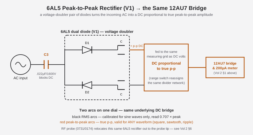
For AC and RF measurements, the function switch routes the incoming signal — after passing through a DC-blocking coupling capacitor (C3, 0.022 µF at 1600 V in the 311-2, chosen to pass the AC signal of interest while keeping any DC component on the line out of the rectifier and bridge) — into the 6AL5, a dual-diode tube wired here as a voltage-doubler peak-to-peak rectifier. Each half of the 6AL5 conducts on opposite half-cycles of the incoming AC waveform, charging a small storage capacitor on each half-cycle; because the two diode/capacitor pairs are stacked (doubled) rather than simply averaged, the resulting DC output is proportional to the full peak-to-peak swing of the input waveform — the distance from its most negative excursion to its most positive — not merely its RMS or its peak-only amplitude.
That rectified DC is then handed off to the very same 12AU7 bridge amplifier described in §3 — the range switch simply reassigns V2A’s measuring grid from the DC divider network to the 6AL5’s rectified output when the function switch is set to AC. This is worth calling out explicitly because it means the AC path and the DC path share almost the entire measurement chain: one bridge, one meter, one zero-adjust, one set of accuracy specs downstream of the rectifier. Only the front-end conversion — dividing DC directly, versus rectifying AC into an equivalent DC first — differs.
2.4.2 Two Calibrations on One Dial: Black RMS Arcs vs. Red Peak-to-Peak Arcs
Because a peak-to-peak rectifier’s output relates differently to RMS depending on the shape of the waveform being measured, Simpson put two separate sets of arcs on the meter face for AC — and reading the correct one for the job matters. The black arcs are calibrated to read RMS, on the assumption that the input is a clean sine wave — for a sine wave, RMS = peak ÷ √2 = a fixed, known fraction of the peak-to-peak swing the 6AL5 actually measures, so Simpson’s calibration bakes that fixed sine-wave conversion factor into the black scale’s numbering. Feed the black arc anything other than a sine wave — a square wave, a sawtooth, a pulse train, ripple riding on a DC supply — and the “RMS” figure it reports is wrong, because the fixed peak-to-RMS ratio the scale assumes no longer holds.
The red arcs, by contrast, read true peak-to-peak directly — exactly what the 6AL5 rectifier physically measures, with no waveform-shape assumption baked in. They’re valid for any waveform: square waves, ripple, pulse trains, whatever’s actually on the line. The full-scale peak-to-peak numbers differ slightly between the two revisions of this instrument — the 311-2’s seven p-p ranges read 4 / 14 / 40 / 140 / 400 / 1400 / 4000 V p-p, while the original 311’s read 4.2 / 14 / 42 / 140 / 420 / 1400 / 4200 V p-p — a small recalibration Simpson made between the two printings that’s worth knowing if you’re cross-checking a 311-2 reading against an original-311 manual’s numbers.
Table 3 — Two Calibrations on One Dial: Black RMS Arcs vs. Red Peak-to-Peak Arcs
| Arc | Reads | Valid for | Full-scale (311-2, per DCV/ACV range) |
|---|---|---|---|
| Black (RMS) | RMS, sine-wave-calibrated | Sine waves only | 1.5 / 5 / 15 / 50 / 150 / 500 / 1500 V RMS |
| Red (p-p) | True peak-to-peak | Any waveform | 4 / 14 / 40 / 140 / 400 / 1400 / 4000 V p-p |
Note — No dB arc is documented on either the 311 or the 311-2 dial or in either manual’s scale description — this is undocumented rather than confirmed-absent by omission alone, but neither manual shows one, so don’t expect a dBm/dBV scale on this instrument.
The 311-2’s AC frequency response is also meaningfully wider than the original 311’s: the 311-2 holds ±5 % from 30 Hz to 1 MHz on the 1.5–50 V ranges (falling off gradually on the higher-voltage ranges), where the original 311 is specified flat only to 100 kHz. That widened bandwidth is a real circuit change between revisions, not just a rectifier swap — worth remembering if a 311-2 reads confidently at a frequency an original 311 manual would have flagged as out of spec.
2.4.3 Why AC and DC Don’t Quite Zero the Same Way — R-32
A subtlety of feeding two structurally different front-ends (the direct resistive divider for DC, the 6AL5 rectifier for AC) into the same bridge grid is that they don’t necessarily arrive at exactly the same DC offset when there’s genuinely zero signal present. Diode rectifiers — the 6AL5 included — exhibit a small contact-potential effect: even with no AC signal applied, the diode junction’s own built-in potential can contribute a small, fixed DC offset to the rectifier’s quiescent output, distinct from (and in addition to) whatever offset exists on the pure-DC divider path. Left uncorrected, that means the bridge’s true zero point shifts slightly depending on whether the function switch sits on DC or AC — the ZERO ADJUST setting that nulls the meter perfectly on DC won’t necessarily null it perfectly on AC, and vice versa.
Simpson’s fix is an internal trimmer, R-32, described in the manuals as the “AC contact-potential pot,” reachable through an access hole in the case side under the carry handle without needing to open the case fully. R-32 is a one-time (or infrequent) internal calibration adjustment — not a front-panel control the operator touches during normal use — that compensates specifically for this AC-vs-DC offset difference, so that the front-panel ZERO ADJUST behaves consistently whichever function is selected. It’s covered as part of the full six-step factory calibration sequence in Vol 5, alongside the PCB-mounted DC CAL (R20), AC CAL (R21), and ZERO SET (R29) pots; it’s mentioned here because it’s a direct, physical consequence of the “two different front ends sharing one bridge” architecture this section describes, and understanding why R-32 exists makes the calibration procedure in Vol 5 make sense rather than feeling like an arbitrary extra step.
2.4.4 The RF Probe: the Same Rectifier, Relocated to the Tip
At frequencies climbing toward and past the megahertz range, the interconnecting cable between the front-panel jack and the internal 6AL5 becomes an antenna and a lossy transmission line in its own right — stray capacitance and lead inductance start to matter, and the internal rectifier is simply too far from the signal to catch it faithfully. Simpson’s answer, as on essentially every VTVM of the era, is an accessory RF (demodulator) probe that carries its own 6AL5 dual-diode rectifier right in the probe handle, so the AC-to-DC conversion happens at the tip, immediately at the test point, and only a low-frequency DC signal has to travel back down the cable to the meter. Plugging the RF probe’s two-circuit phone plug into the front-panel RF PROBE jack automatically disables the internal AC rectifier and both feeds the probe’s own 6AL5 filament power and carries its rectified output back to the meter — one jack does both jobs.
The 311’s original RF probe is part number 0731, flat to ±5 % from 50 Hz to 100 MHz, reading 0–150 V RMS / 0–400 V p-p with 10 pF input capacitance. The 311-2 lists a revised High Frequency Probe, part 0174, specified from 10 kHz to 250 MHz — a substantially higher top-end frequency than the original probe. Between the internal-rectifier AC path and the RF-probe path, the instrument covers 30 Hz clear through 250 MHz — enough to reach into VHF service work, well beyond what its DC/AC internal circuitry alone would manage.
That 10 pF input capacitance figure matters more than it might look at first glance. At RF, a probe’s input capacitance sets a frequency-dependent shunt impedance right at the test point — a 10 pF cap presents roughly 1.6 kΩ of reactance at 10 MHz, falling to around 65 Ω by 250 MHz — low enough, on a sensitive RF tank or tuned circuit, to noticeably detune the very stage being probed if the probe capacitance were much larger. Relocating the rectifying diode to the probe tip (rather than running the raw RF signal down a length of coaxial cable to an internally-mounted 6AL5, as the DC and low-frequency AC paths do) is precisely what keeps that input capacitance as low as 10 pF: the RF energy only has to travel the short distance from the test point to the diode junction inside the probe body, converting to a comparatively slow-moving DC signal before it enters the cable — the cable’s own capacitance and any pickup along its length no longer matter once the signal riding on it is DC rather than RF. Full probe handling procedure and accuracy notes are in Vol 4; physical description and part-number cross-reference are in Vol 3.
2.5 The Ohms Circuit — the Internal Battery Doing the Sourcing
2.5.1 Why Ohms Needs Its Own Source
DC and AC volts both measure a voltage the circuit under test is already producing. Resistance measurement is different by nature: a resistor sitting on the bench (or, more commonly, still in circuit but powered down) produces no voltage of its own — to read it, the instrument has to supply a known current or voltage itself and observe the resulting drop across the unknown resistance. On the 311/311-2, that source is deliberately modest: a single 1.5 V “size C” dry cell (Simpson’s battery B1, part 1-111801), clamp-mounted inside the case, its polarity marked for correct replacement.
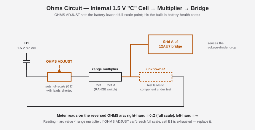
With the function switch on OHMS, that 1.5 V cell is connected in series with a range-selected multiplier resistor (chosen by the RANGE switch, one value per decade — ×1 through ×1M) and the unknown resistance connected across the test leads. Current flows from the cell, through the multiplier resistor, through the unknown resistance, and back — and the voltage that develops across that series string, tapped at the node between the multiplier resistor and the unknown resistance, is what the 12AU7 bridge actually measures. A small unknown resistance drops little of the available voltage at that tap; a large one drops nearly all of it — which is why the ohms arc reads backward relative to the volts arcs: full-scale deflection corresponds to 0 Ω (leads shorted, no resistance to drop voltage across, maximum current), and the pointer falls back toward the low end of the scale as resistance rises toward open circuit.
2.5.2 OHMS ADJUST Is a Battery-Health Check, Not Just a Zero
Because the cell’s actual terminal voltage isn’t a fixed, known 1.5000 V — it sags as the cell discharges and drifts with temperature and age like any dry cell — the ohms circuit needs its own calibration control separate from the DC/AC bridge’s ZERO ADJUST. That’s OHMS ADJUST: with the test leads shorted together (0 Ω applied), OHMS ADJUST is turned until the pointer reaches exactly full scale, compensating for whatever the cell’s actual current output happens to be that day. This has a genuinely useful side effect that doubles as routine bench diagnostics: if OHMS ADJUST cannot be turned far enough to bring the pointer to full scale with the leads shorted, the internal cell has weakened past usable range and needs replacing. No separate battery-check procedure is needed — the ohms function tests its own power source every time it’s used, before a single resistance reading is trusted.
Table 4 — OHMS ADJUST Is a Battery-Health Check, Not Just a Zero
| Range switch position | Center-scale value (original 311, authoritative table) |
|---|---|
| ×1 | 10 Ω |
| ×10 | 100 Ω |
| ×100 | 1,000 Ω |
| ×1K | 10 kΩ |
| ×10K | 100 kΩ |
| ×100K | 1 MΩ |
| ×1M | 10 MΩ |
Note — The 311-2 manual’s own ohms table lists only six rows and appears to mislabel the RX10K row’s center value as “1 megohm” (a decade high) while omitting the ×100K row entirely — almost certainly a printing error rather than an intentional design change, since the underlying multiplier-resistor circuit is unchanged from the 311. This discrepancy is [UNCERTAIN] for the 311-2 printing specifically; treat the clean seven-range original-311 table above as authoritative for both revisions unless a corrected 311-2 printing turns up. Ohms accuracy on both revisions is specified as ±3 degrees of arc.
2.5.3 Reading the Reversed Arc
Because a resistance reading is taken from arc position × range multiplier rather than a direct linear volts-style scale, the ohms arc is drawn with its own geometry, crowded toward the high-resistance (low-deflection) end and expanded toward the low-resistance (full-scale) end — visible as the compressed OHMS arc in the dial photograph above, alongside the RMS and peak-to-peak arcs it shares the dial face with. A reading of, say, “7” on the ×1K range multiplies out to 7 kΩ; the same “7” on the ×100K range is 700 kΩ. This backward, non-linear layout is standard across essentially every analog ohmmeter, tube or otherwise — it’s a direct consequence of Ohm’s law applied to a series voltage-divider sensing scheme, not a Simpson-specific quirk. The center-scale point (where the arc’s spacing is most linear and easiest to read precisely) is the range’s “characteristic” value — 10 Ω on ×1, 10 MΩ on ×1M — which is why choosing a range that puts the expected reading near mid-scale, rather than jammed against either end of the arc, gives the most accurate result.
Worked example: suppose the RANGE switch is on ×1K and the pointer settles at the arc position labeled “4.7” — reading = 4.7 × 1,000 = 4.7 kΩ. Move the same test leads to a much larger resistor without changing anything else and the pointer creeps down toward the crowded, compressed left-hand end of the arc where two adjacent printed graduations might span tens or hundreds of kilohms apiece — exactly the situation the range switch exists to avoid, by stepping the multiplier up (say, to ×10K) so the same physical resistance now reads back up near the arc’s open, easy-to-interpolate right-hand region instead. This is the same “pick the range that lands the reading mid-scale” discipline that applies to reading any non-linear ohms arc, tube-era or modern analog alike.
2.6 The One Semiconductor: CR-1, the Power-Supply Rectifier
It’s worth being precise about what “all-tube” means for this instrument, because it is easy to overstate. The 311-2’s B+ and heater supply — the power that runs the 12AU7 bridge and 6AL5 rectifier, and that indirectly powers the meter’s electronics (though not the meter movement itself, which is purely electromechanical) — is derived from the AC line through power transformer T1 and rectified by CR-1, a silicon rectifier diode rated 750 mA (Simpson part 1-117943). That makes CR-1 the one semiconductor junction anywhere in the instrument. It is not a measuring element in any sense — it doesn’t touch the signal path, the bridge, the rectifier, or the ohms circuit; its sole job is turning line AC into the DC (and, via the transformer’s other windings, the AC heater supply) that keeps V1 and V2 running. So “all-tube VTVM” describes the measuring circuitry accurately — DC amplification (12AU7), AC/RF rectification (6AL5), and even the accessory RF probe’s own rectifier are tubes throughout — while the power supply, like nearly every piece of tube gear built after the mid-1950s, quietly moved off the old tube rectifier (a 5Y3 or similar, common in earlier designs) and onto a compact silicon diode instead. This is worth flagging for refurbishing purposes too: CR-1 is a modern, easily-sourced part, and its failure mode (open or shorted) is a straightforward power-supply fault, not a calibration issue — see Vol 5 for the full refurb treatment of the supply and its filter capacitor C5.
2.7 The Movement’s Role in Bridge Sensitivity
The bridge theory above describes what unbalances and why, but it’s the meter movement itself that turns that unbalance into a readable number, and its sensitivity is part of the circuit’s overall design, not an independent afterthought. The 311-2 uses a custom Simpson D’Arsonval movement (part 15-AC2311-2) specified at 200 µA full-scale with roughly 1,000 Ω internal resistance — figures that come from secondary sourcing (Nuts & Volts) corroborated by the model-specific Simpson part number, rather than a number quoted verbatim in either manual read for this doc, so treat the precise 200 µA/1 kΩ pairing as [LIKELY] rather than manual-confirmed.
What that sensitivity buys the bridge design is straightforward: the smaller the current needed to swing the pointer full-scale, the smaller a plate-current imbalance between V2A and V2B needs to be to produce a full-scale reading, which in turn means the bridge can be built with comparatively modest amplification and still resolve small input differences — 200 µA is a genuinely sensitive movement by the standards of general-purpose panel meters, closer to the sensitivity used in bridge and null instruments generally than to a typical 1 mA or 50 µA utility movement. A less sensitive movement would force a design choice between a bigger, harder-to-stabilize amplification factor ahead of the meter, or reduced overall resolution — neither of which suits a precision bench instrument aiming for ±3 % DC accuracy across a 22 MΩ input. The movement’s own construction and specific placement in the case are covered in Vol 3; the point here is that its sensitivity spec and the bridge’s gain requirements were necessarily designed together, not chosen independently.
Note — The “custom” designation on the movement’s part number (rather than a generic off-the-shelf meter part) is itself a real, confirmed detail — Simpson wound this movement specifically for the 311-2, consistent with the instrument being built as a dedicated precision bridge readout rather than adapted from a stock panel meter. Whether that custom winding delivers a meaningfully better linearity than a comparable stock movement is not something either manual claims explicitly — treat any specific “linearity advantage” framing as [UNCERTAIN] marketing-adjacent language rather than a sourced Simpson spec.
2.8 The Three Corrections Worth Repeating
Because this instrument’s identity gets garbled in casual secondary write-ups more often than most, it’s worth collecting the corrections this volume has made along the way into one place before moving on — these are the three points a hostile fact-check of this instrument should come back to first.
Table 5 — The Three Corrections Worth Repeating
| Common error | What’s actually true | Where it’s covered above |
|---|---|---|
| ”12AU7/12AX7” tube pair, or 12AX7 as “the bridge” | Only two tubes total: 12AU7 (V2, the balanced-bridge amplifier, used on every function) and 6AL5 (V1, the AC/peak-to-peak rectifier, used only on AC/RF). No 12AX7 anywhere in the signal path. | §3, §4 |
| ”~11 MΩ” DC input, following the RCA/EICO/Heathkit convention | 22 MΩ on all ranges, printed on the front panel itself and stated identically in both the 1958 and 1966 manuals — Simpson deliberately doubled the industry-typical figure. | §2 |
| A “late FET-input 311” variant | No FET-input 311 exists. The FET/solid-state Simpson VOM is a wholly separate model, the 313 — not a 311 revision. The 311 line (311/311-1/311-2/311-3) stayed all-tube throughout. | Vol 1’s lineage discussion |
2.9 How It All Comes Together
Table 6 — How It All Comes Together
| Function | Source of the measured signal | Path to the bridge | Arc read |
|---|---|---|---|
| DC volts | Test-point voltage via probe | R6 (≈1 MΩ, probe DC position) → 22 MΩ divider network → Grid A | DC volts scale (linear) |
| AC volts (internal) | Test-point AC via probe, straight-through | C3 blocking cap → 6AL5 voltage-doubler rectifier → Grid A | RMS (black) or p-p (red) |
| AC/RF (external RF probe) | Test-point AC at the probe tip | 6AL5 in the RF probe handle (0731/0174) → cable → Grid A | RMS (black) or p-p (red) |
| Ohms | Internal 1.5 V “C” cell (B1) | OHMS ADJUST → range multiplier R → unknown R → sensed drop → Grid A | OHMS arc (reversed, ×multiplier) |
Every one of those four rows terminates at the same place: Grid A of the 12AU7 balanced bridge, unbalancing it against Grid B’s stable reference, deflecting the same 200 µA movement, read against whichever arc the function/range combination calls for. That’s the payoff of the balanced-bridge architecture — one precision analog computing element doing the job of four separate measurement circuits, with only the front-end conditioning (a resistive divider, a rectifier, or a battery-driven divider) differing function to function. Vol 3 picks this theory up at the hardware level — the actual PCB layout, part numbers, front-panel control functions, and range-switch wiring that implement everything described here in this specific unit. Vol 4 covers the operating sequence — warm-up, zeroing, range selection, probe handling, and the safety practices (mains-referenced case ground, HV probe limits) that follow directly from the circuit theory above. Vol 6’s cheatsheet distills the two-VTVM bench workflow this instrument shares with the B&K Dynamic 375, including where their independent front ends (22 MΩ balanced-bridge tube here, versus the B&K’s own input stage) make them a genuinely independent cross-check rather than two meters reading off the same error.
⚠ Danger — Everything on the signal side of this circuit runs at low, safe potentials — but the B+ supply behind CR-1 and the plate circuits of V1/V2 do not, and the case is tied to the AC line’s safety ground via the 3-wire cord. Treat any internal work as mains-adjacent per
_shared/legal_ethics.mdbefore opening the case, and never exceed 30 kV safe operating voltage on the HV probe even though its scale marking reads to 50,000 V (see §2 and Vol 4 for the full HV-probe procedure).
Sources
- Simpson Electric Co., Operator’s Manual — Vacuum Tube Voltmeter Model 311-2, © 1966 (part 5-110700). https://www.simpson260.com/downloads/simpson_311-2_user_manual.pdf — bridge/rectifier tube section, 22 MΩ input spec, ohms battery and table, parts list (R6, R15, R17, R33–R39, C3, C5, CR-1, movement 15-AC2311-2), Fig. 4 schematic.
- Simpson Electric Co., Operator’s Manual — Vacuum Tube Voltmeter Model 311, © 1958 (printing 1-62-JM-BL-Rev.1). https://simpson260.com/downloads/simpson_311-1_user_manual.pdf — 22 MΩ input, 7-range ohms table (×1…×1M), RF probe (0731) and HV probe (0732) specifications, AC frequency response.
- Simpson 311-2 manual mirror, Internet Archive: https://archive.org/details/Simpson_311-2_VTVM
- Manual index, BAMA: https://bama.edebris.com/manuals/simpson/311-2
- Nuts & Volts, “Vintage Tek: The Vacuum Tube Voltmeter” — https://www.nutsvolts.com/magazine/article/vintage-tek-the-vacuum-tube-voltmeter (secondary corroboration on movement spec and general bridge/rectifier theory; its 11 MΩ figure is superseded here by Simpson’s own 22 MΩ spec — see §2).
- Radiomuseum, Simpson VTVM family (312/303 context): https://www.radiomuseum.org/r/simpson_vacuum_tube_volt_ohmmete.html
- Simpson 313 Solid-State VOM product listing (confirms the FET/solid-state Simpson is a distinct model, not a 311 variant): https://www.manualslib.com/products/Simpson-313-Solid-State-Vom-14060996.html
- Recycled Goods, Simpson 311 listing (dial and control-panel photography): https://recycledgoods.com/simpson-311-vacuum-tube-volt-ohmmeter/