Simpson Model 311-2 VTVM · Volume 3
Simpson 311-2 — Vol 3: Inside This Unit — Hardware, Controls & Ranges
Two tubes, one silicon diode, a 22 MΩ divider chain, and a seven-position switch that does the work of fourteen.
3.1 Scope of This Volume
Vol 2 covered how a VTVM’s balanced bridge, rectifier, and ohms circuit work in general terms. This volume is about this specific box — the four knobs and three jacks on the front panel, the active devices behind them, the meter movement they drive, and the complete range set the RANGE switch selects. It closes with the two features that make the 311-2 worth keeping on the bench next to a B&K 375: the 22 MΩ DC input (double the usual VTVM figure) and the zero-center “D.C. Galvanometer” mode for null and alignment work. Operating procedure and probe technique are Vol 4’s job; calibration and refurb detail live in Vol 5. Everything below is corroborated against the Simpson 311 (© 1958) and 311-2 (© 1966) Operator’s Manuals — see Sources.
Note — the 311 and 311-2 share the same case, panel layout, and control set; the 311-2’s changes are internal (a printed-circuit-board rebuild of the same circuit, plus a widened AC frequency response — Vol 2 §3). The photographs in this volume are of an original Simpson 311; captions say so. Read “Model 311” silkscreened on the panel below as the panel, not as a claim that the pictured unit is a 311-2.
3.2 Front Panel — Controls & Jacks
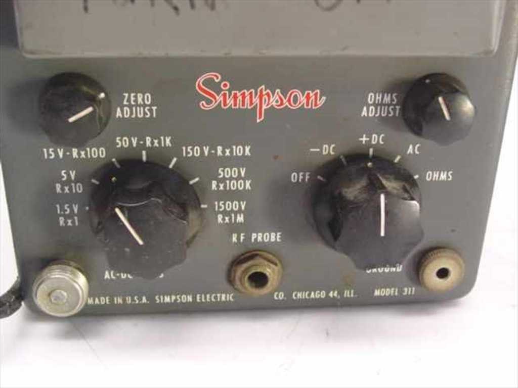
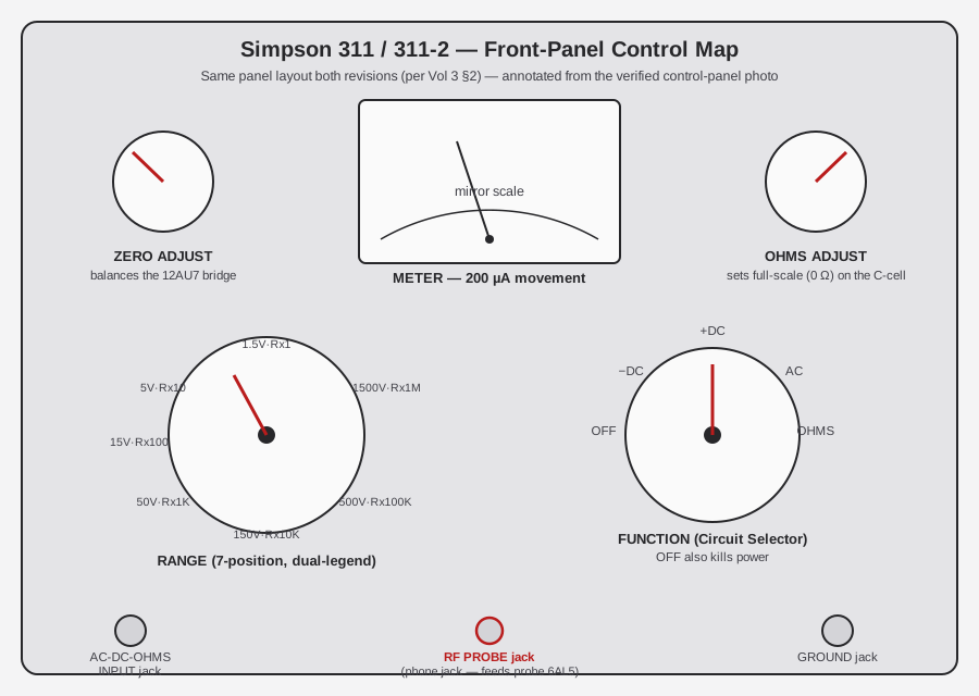
The 311/311-2 front panel is deliberately spare: one range switch, one function switch, two small balancing knobs, and three jacks. Everything else the operator needs is printed on the dial or molded into the case.
3.2.1 The Seven-Position Range Switch
The RANGE switch is the single busiest control on the instrument — Simpson dual-purposed it so one 7-position rotary does the work a lesser meter would split across a range switch and an ohms-multiplier switch. Each detent carries two legends stacked on the dial: a DCV/ACV-RMS full-scale value on top, an ohms multiplier (Rx) underneath. Reading clockwise off the actual panel:
Table 1 — an ohms multiplier (Rx) underneath. Reading clockwise off the actual panel
| Detent | DCV / ACV-RMS full scale | Ohms multiplier | Ohms center-scale (×10 Ω base) |
|---|---|---|---|
| 1 | 1.5 V | Rx1 | 10 Ω |
| 2 | 5 V | Rx10 | 100 Ω |
| 3 | 15 V | Rx100 | 1,000 Ω (1 kΩ) |
| 4 | 50 V | Rx1K | 10 kΩ |
| 5 | 150 V | Rx10K | 100 kΩ |
| 6 | 500 V | Rx100K | 1 MΩ |
| 7 | 1500 V | Rx1M | 10 MΩ |
The same switch position simultaneously sets the voltage range and the ohms multiplier — there’s no way to combine, say, the 1.5 V voltage range with the Rx100K ohms multiplier. That coupling is a consequence of the divider network being one physical resistor chain shared between the DC/AC and OHMS functions; the FUNCTION switch (below) decides which mode reads the tap the RANGE switch selected. See §6 for the full range table with the actual full-scale endpoints, and §4 for why the 311-2 manual’s own printed ohms table disagrees with this one at position 5.
A worked walkthrough, because the coupled dual-legend takes a minute to get used to on a first encounter: say you want to check a grid-bias point expected to read around 8 V DC. RANGE goes to position 3 (“15 V · Rx100”) — you’re reading the DCV legend on top, so the Rx100 half underneath is simply along for the ride and does nothing until you turn FUNCTION to OHMS. FUNCTION goes to +DC (or −DC if the expected polarity is negative), ZERO ADJUST gets touched with the probe and ground shorted, and the meter reads directly against the 15 V arc. Now say the next task on the same bench is checking a suspect resistor believed to be around 1.2 kΩ: RANGE moves to position 3 again — this time you’re reading the Rx100 legend, ignoring the 15 V figure above it — FUNCTION goes to OHMS, OHMS ADJUST sets full scale with the leads shorted, and the pointer reads against the OHMS arc, multiplied by 100 (a midscale reading of “12” means 1,200 Ω). Same switch position, two completely different numbers read off two completely different arcs, selected entirely by where FUNCTION points.
3.2.2 The Function (Circuit Selector) Switch
Simpson’s manual calls this the Circuit Selector; the panel silkscreen just says the position names: OFF · −DC · +DC · AC · OHMS.
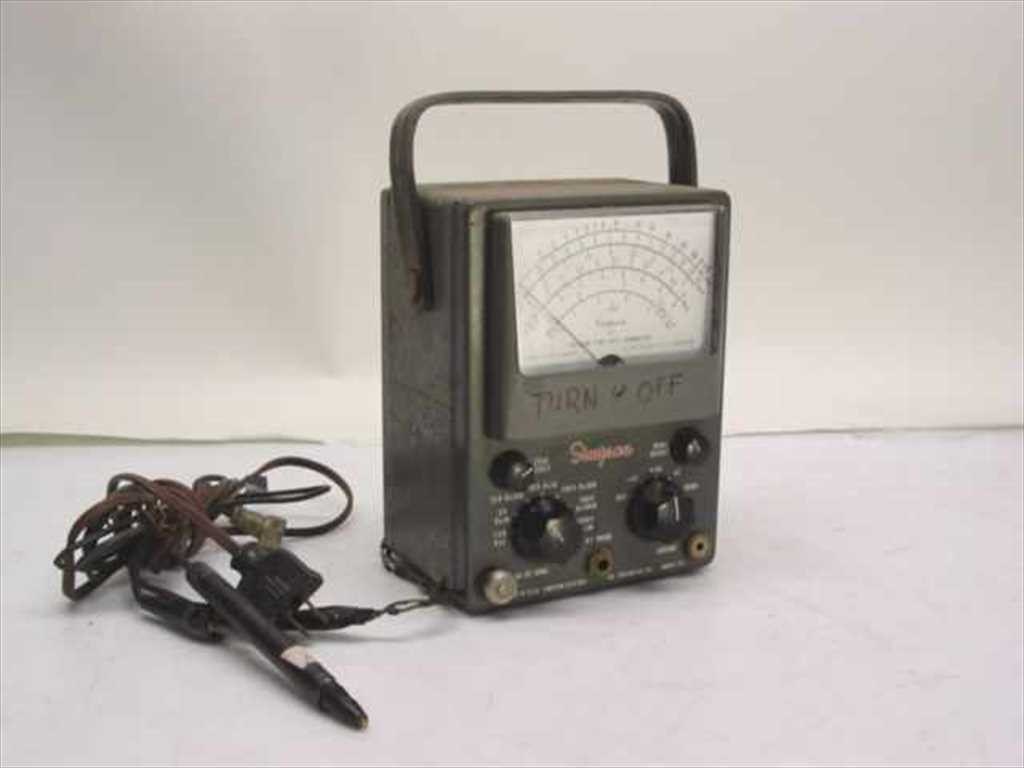
Note — OFF is not a parking position with the meter idle — it is the only position that removes line power from the transformer primary. Everything else (−DC, +DC, AC, OHMS) is a powered state. The handwritten “TURN OFF” reminder scrawled on the case in the photographs below is a previous owner’s own aide-mémoire, not a factory marking — but it’s good bench discipline: a tube VTVM left on the AC or OHMS position with nothing connected still burns tube heaters and drains the internal battery through no fault of its own.
- −DC / +DC — select DC measurement with the meter polarity reversed between the two; on a VTVM with no internal reversing relay, this lets you probe either polarity without swapping leads. Both route the probe through the 22 MΩ divider into the 12AU7 bridge (Vol 2 §2).
- AC — routes the probe through the AC divider (2.2 MΩ minimum at 60 Hz) into the 6AL5 peak-to-peak rectifier, whose output DC then drives the same 12AU7 bridge.
- OHMS — disconnects the external divider and inserts the internal 1.5 V “C” cell (B1) and the RANGE switch’s multiplier resistor in series with the unknown resistance; the voltage dropped across the unknown is read by the bridge on a reverse (right-hand-zero) arc.
3.2.3 Zero Adjust and Ohms Adjust
Two small knobs do all the balancing this instrument needs — there is no autoranging, no autozero, and (per the manuals read for this dive) no chopper-stabilization; the operator zeroes it by hand every time range or function changes.
Table 2 — Zero Adjust and Ohms Adjust
| Control | What it does | When you touch it |
|---|---|---|
| ZERO ADJUST | Balances the 12AU7 bridge electrically — with the probe and ground leads shorted together, this knob brings the meter to exactly 0. | Before every DC or AC measurement, and again whenever RANGE or FUNCTION changes — Simpson’s own instruction, not a suggestion. |
| OHMS ADJUST | Sets the OHMS full-scale (“0 Ω,” leads shorted) deflection, compensating for the C-cell’s state of charge. | Every time you switch to OHMS or change the ohms multiplier; if it can’t reach full scale, the battery is dead — replace it (Vol 5). |
There is a third zero adjustment the front panel doesn’t expose: a slotted mechanical meter-zero screw under the scale glass, set with the power off and the pointer resting at true mechanical zero. That one is a set-and-forget screwdriver adjustment, not a per-measurement knob — see Vol 5.
Note — an appreciable zero shift when flipping between AC and DC (beyond what ZERO ADJUST corrects range-to-range) is normal aging behavior in a 12AU7-bridge VTVM and is trimmed out internally by R-32, an AC contact-potential pot reachable through a hole in the case side under the carry handle — not a front-panel control, and not something to chase with ZERO ADJUST alone. Vol 5 covers the full six-step factory cal sequence that sets R-32 alongside the PCB-mounted R20/R21/R29.
3.2.4 Jacks, Pilot Lamp, and Case Hardware
Table 3 — Jacks, Pilot Lamp, and Case Hardware
| Jack / feature | Location | Purpose |
|---|---|---|
| AC-DC-OHMS probe jack | Bottom-left of panel | Accepts the standard probe. The probe body itself carries a slide switch: AC/OHMS position makes a direct connection; DC position switches in a series isolating resistor (≈1 MΩ, R6 in the 311-2 parts list) at the tip to block RF pickup and prevent oscillation on the high-Z DC grid. The probe tip itself uses a “new style” design with a built-in S-hook, so the operator can hang the probe on a test point and look away toward the meter without holding it steady by hand — a small but genuinely useful bench-ergonomics detail Simpson called out specifically in the 311 manual. |
| RF PROBE jack | Bottom-center, between the two knob clusters | A two-circuit phone jack. It both carries the rectified signal back from the accessory RF probe and feeds that probe’s own internal 6AL5 filament power — and inserting the RF probe automatically disables the instrument’s internal AC rectifier, so the RF probe’s diode does the rectifying instead. See §7. |
| GROUND jack | Bottom-right | Accepts the ground/return lead (insulated alligator clip at the far end). |
| Pilot lamp (L1) | Between the GROUND and INPUT jacks | A “cloudy-clear” indicator lamp — on whenever the FUNCTION switch is not at OFF. |
| Carry handle | Top of case | Folds flat; the whole instrument is 4½ lb net / 6 lb shipping in a 7½ in H × 5⅝ in W × 4½ in D metal case — genuinely portable, unlike a full-size bench VTVM. |
3.3 The Meter: Movement, Scale, and Mirror
3.3.1 The 200 µA Movement
Every VTVM’s whole reason for existing is to let a delicate, low-current meter movement read a high-impedance node without loading it — the tube front end does the loading-avoidance, and the movement just has to be sensitive and accurate. Simpson used a custom D’Arsonval movement, part 15-AC2311-2, model-specific (the part number itself confirms it isn’t an off-the-shelf mechanism).
Note — the movement’s full-scale current and internal resistance — commonly quoted as 200 µA, ~1,000 Ω — are corroborated by secondary sources (Nuts & Volts’ VTVM survey) and are consistent with the model-specific part number, but no Simpson manual page read for this dive prints those two numbers directly. Treat 200 µA / ~1 kΩ as [LIKELY], not a verbatim Simpson spec.
3.3.2 Reading the Mirror Scale
The dial is a genuine mirror scale — a strip of mirror runs beneath the arcs so the operator lines the needle up with its own reflection before reading, eliminating parallax error. Four families of arc share the one face:
Table 4 — the one face
| Arc | Color | Reads | Valid for |
|---|---|---|---|
| RMS | Black | AC volts, calibrated in true RMS | Sine waves only |
| Peak-to-peak (P-P) | Red | AC volts, true peak-to-peak | Any waveform shape |
| OHMS | Black, reverse (right-hand zero) | Resistance × the RANGE switch’s multiplier | — |
| DC zero-center | Black, “−0+” marking at mid-scale | DC null/balance work (§6) | — |
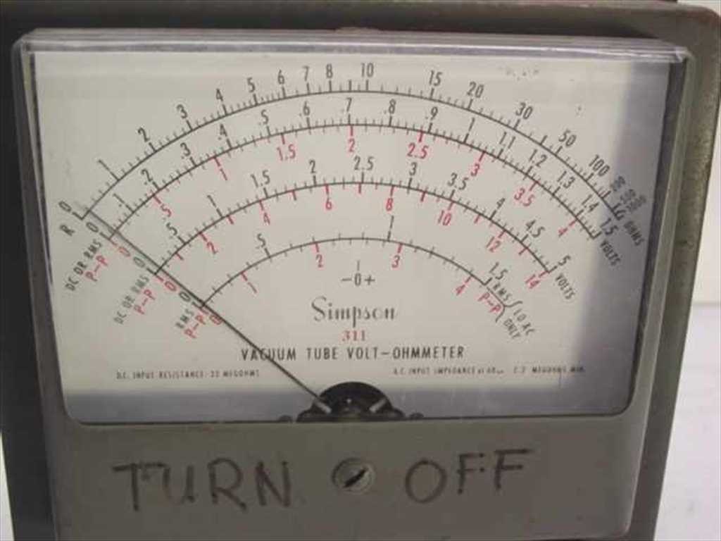
Note — no dB arc appears on this dial, and neither manual’s scale description mentions one. Many contemporary VTVMs carry a dB arc; the 311/311-2 is not documented to — don’t assume it has one without a photo of the specific unit’s dial confirming it. [NOT FOUND]
The dial legend visible in the photograph above is worth dwelling on, because it’s the instrument answering its own headline question in ink: “D.C. INPUT RESISTANCE: 22 MEGOHMS.” That’s not a derived figure or a secondary-source estimate — it’s printed on the meter face Simpson shipped.
Look closely at the same close-up and the mirror strip itself is visible as a bright band running the length of every arc, directly beneath the black ink of the scale printing. It isn’t decorative — it’s a practical parallax-elimination tool, and it’s worth understanding once rather than treating as trivia:
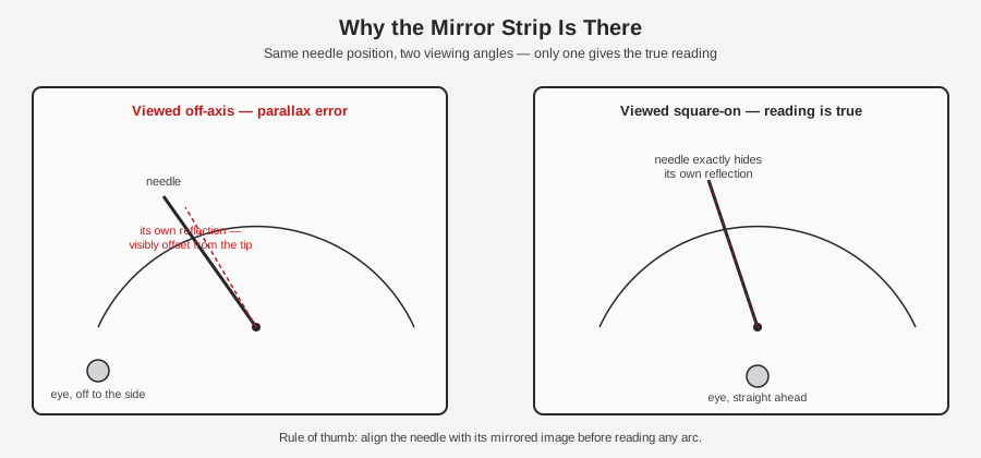
Note — because the needle is a real object standing some small distance in front of the scale face, viewing it from any angle other than dead-on makes it appear to point at a different value than it mechanically does — the same effect that makes a car’s analog speedometer needle look like it’s reading differently to the driver than to a passenger. The mirror strip gives an unambiguous check: move your head until the needle visually covers its own reflection, and parallax is exactly zero at that instant. On a ±3 % DC / ±5 % AC instrument, a sloppy reading angle can easily eat as much of the error budget as the instrument’s own drift does — cheap technique, real accuracy.
3.4 Active Devices: Two Tubes and One Diode
The 311-2 is an all-tube VTVM. Two tubes do every bit of measuring; one silicon diode does none of it — it only makes DC for the tube supply. This is the single most important hardware fact to get right about this instrument, because the wrong tube complement (a stray “12AX7,” a 6AL5 mislabeled as “the bridge”) is the most common scaffold-level error in secondhand write-ups.
Table 5 — Active Devices: Two Tubes and One Diode
| Device | Type | Role | 311-2 part number |
|---|---|---|---|
| V1 | 6AL5 (miniature dual diode) | Peak-to-peak rectifier for all AC voltage measurements | 3-811288 (“6AL5 aged”) |
| V2 | 12AU7 (miniature dual triode) | Balanced-bridge DC amplifier — the active element for every measurement: DC, AC-after-rectification, and ohms | 3-310744 (“12AU7 aged”) |
| CR-1 | Silicon rectifier diode | Power-supply B+/heater rectifier off transformer T1 — not a measuring element | 1-117943, 750 mA |
3.4.1 V1 — 6AL5 Peak-to-Peak Rectifier
The 6AL5 sits in the AC signal path only. On the AC function, it converts the incoming AC waveform to a proportional DC voltage (voltage-doubler / peak-to-peak topology — Vol 2 §3 has the circuit-theory detail) which the 12AU7 bridge then measures exactly as if it were a DC input. It plays no role at all on DC or OHMS.
⚠ Danger — do not describe the 6AL5 as “the bridge.” Simpson’s own manual reserves “bridge” for the 12AU7 circuit; the 6AL5 is downstream of it, feeding the bridge a rectified signal. Getting this backwards is the scaffold error this dive corrects.
3.4.2 V2 — 12AU7 Balanced-Bridge Amplifier
The 12AU7’s two triode sections form the two arms of a DC balanced bridge; the 200 µA movement sits across the bridge output and reads the imbalance. With no signal applied, ZERO ADJUST nulls the bridge so the meter rests at 0. An applied DC voltage (direct on DC, or post-rectification on AC, or as an IR drop on OHMS) unbalances the bridge proportionally and deflects the meter. Because both triode halves share one envelope, one heater, and one supply, drift common to both — heater voltage sag, warm-up transients, gradual aging — largely cancels between the two arms, which is why a balanced bridge front end is more stable over a session than a single-triode stage would be.
Note — there is no 12AX7 anywhere in this instrument. Some secondhand write-ups conflate the 12AU7 with its higher-mu cousin the 12AX7; Simpson specifically chose the low-mu 12AU7 for its stiff, linear transfer characteristic in a bridge role. If a source names a 12AX7 in a 311 or 311-2, that source is wrong.
Simpson’s own instruction on replacing V2: a fresh 12AU7 must be aged ≥48 hours, installed and powered, before the instrument is recalibrated — the parts list itself specifies “12AU7 aged” and “6AL5 aged” rather than listing generic replacement part numbers, which is Simpson quietly telling the service tech that a cold-swapped tube will not hold calibration yet. Full refurb sequencing is Vol 5.
3.4.3 CR-1 — the Power-Supply’s One Semiconductor
Even a fully “all-tube” 311-2 has exactly one semiconductor in it: CR-1, a 750 mA silicon rectifier diode off the power transformer T1, doing conventional line-to-DC conversion for the B+ and heater supplies. It never touches the signal being measured. Calling the 311-2 “hybrid” because of CR-1 overstates it — a power-supply rectifier diode is present in essentially every tube instrument built after silicon rectifiers got cheap in the late 1950s and doesn’t change the instrument’s measuring front end at all.
⚠ Danger — there is no FET-input Model 311. The FET/solid-state member of the Simpson VOM/VTVM family is a different instrument, the Model 313 “Solid-State VOM.” If you’re reading a listing or forum post that describes a “FET 311,” it has conflated the 311 with the 313 — the 311 line stayed all-tube through the 311-2 and 311-3.
3.4.4 The RF Probe’s Own 6AL5
The accessory high-frequency probe (§7) is not a passive pickup — it carries its own 6AL5 dual diode mounted in the probe handle, doing full-wave rectification right at the test point before the signal travels down the cable, which is what lets it work usefully up into the tens or low hundreds of MHz where cable capacitance would otherwise swamp an internally-rectified reading. Plug the RF probe in and the instrument, for that measurement, effectively has three tubes present: the RF probe’s 6AL5 doing the rectifying, and the main chassis’s 12AU7 bridge reading the result (the internal 6AL5 is disabled automatically). The probe draws its filament power from the instrument through the RF PROBE jack’s second circuit.
3.4.5 Tube Sockets, Heaters, and the “Aged” Requirement in Practice
Both V1 and V2 are common 9-pin miniature (noval) envelope tubes — the 6AL5 and 12AU7 were mass-market parts through the entire tube era, used across countless radios, TVs, and other test equipment, which is the practical upside of an all-tube design built this late: neither tube is hard to source today, unlike the instrument’s custom meter movement or its probes (Vol 5 covers sourcing in detail). Both run off the shared heater supply that CR-1 and T1 provide; a cold, just-installed replacement tube reaches thermal and electrical stability only after some warm-up, which is the physical basis for Simpson’s 48-hour aging instruction (§5) — the tube’s transient characteristics (cathode activation settling, contact-potential drift, gas outgassing in a fresh envelope) need time under power to stabilize before the bridge balance they’re part of can be trusted to hold.
⚠ Danger — don’t shortcut the 48-hour aging period on a freshly swapped 12AU7 by recalibrating immediately and calling it done. A bridge zeroed against an unstable tube will drift back out over the following day or two as the tube finishes settling, and the recalibration will have to be repeated — Simpson’s parts list flagging both replacement tubes as “aged” rather than just listing a generic part number is the manufacturer telling the service tech this isn’t optional.
3.5 The Signature Feature: 22 MΩ DC Input
This is the number to remember about the 311/311-2, and it’s worth stating plainly: DC input resistance is 22 megohms, on every range, on both revisions. Simpson’s own manual text is verbatim on this point in both the 1958 and 1966 printings: “Input resistance is 22 megohms for all ranges.”
Table 6 — The Signature Feature: 22 MΩ DC Input
| Instrument | DC input resistance | Note |
|---|---|---|
| Typical contemporary VTVM (RCA WV-98, EICO, Heathkit) | ~11 MΩ | 1 MΩ probe isolating resistor + 10 MΩ divider — the industry-standard figure |
| Simpson 311 / 311-2 | 22 MΩ | Simpson deliberately built a larger divider network — roughly double the usual figure |
| Simpson 311/311-2 with the DC HV probe (0732) fitted | 2,200 MΩ | The HV probe adds its own multiplier resistor in series |
Physically, this isn’t one resistor — it’s a chain: R17 (20 MΩ), R34–R37 (22 MΩ), R15 (5 MΩ), and R33/R38/R39 (≈3.5–3.8 MΩ) among others, tapped at different points by the RANGE switch to set each range’s divide ratio while presenting a constant 22 MΩ to the probe tip regardless of which range is selected. That’s a meaningfully harder design target than a single fixed divider, and it’s the resistor group most worth measuring during a refurb (Vol 5) — decades-old carbon-composition or film resistors in this value range are exactly the parts that drift high with age, and a drifted divider degrades accuracy on every range at once.
Why 22 MΩ matters in practice: a VTVM’s whole value proposition versus a 20 kΩ/V analog VOM — the Simpson 260 on the same bench — is that the tube grid draws essentially no current, so the meter doesn’t load the circuit under test. Doubling the input resistance versus a typical 11 MΩ VTVM pushes that advantage further still, mattering most on high-impedance nodes: AVC lines, grid-leak bias points, and other spots in tube circuitry where even an 11 MΩ probe would measurably sag the voltage being read. The instrument’s sibling on Jeff’s bench, the B&K Dynamatic 375, carries its own high-Z input for the same reason — Vol 6 works out where the two units agree and where the Simpson’s extra input resistance is the deciding factor. AC input impedance, for contrast, is 2.2 MΩ minimum at 60 Hz — an order of magnitude lower than the DC figure, because the AC path runs through the 6AL5 rectifier rather than straight into a tube grid.
3.6 Warm-Up and Bridge Stability
A balanced-bridge VTVM is only as good as how well-matched the two halves of its bridge are at the moment you read it, and a cold 12AU7 is not a stable bridge element. Simpson’s calibration procedure calls for at least 1 hour of warm-up before trusting a calibration check, and normal day-to-day use carries the same expectation informally: switch the instrument on, let the tube heaters and the rest of the circuit reach thermal equilibrium, and only then treat a ZERO ADJUST setting as good until the next range or function change.
Note — how often to fully re-zero and how often to fully recalibrate are two different questions with two different answers. Re-zeroing (ZERO ADJUST, OHMS ADJUST) is a per-measurement-session, per-range-change, per-function-change habit — the manuals are explicit about this. Recalibrating against a known reference (Vol 5’s six-step procedure) is called for after a tube change, after any internal repair, or when periodic verification against a reference standard shows drift — not on a fixed calendar interval. A “rezero every couple of months” cadence sometimes quoted for VTVMs generally is a reasonable maintenance habit but is not a Simpson-specified interval for this instrument — treat it as [UNCERTAIN] practical guidance, not manual doctrine.
The AC↔DC zero shift mentioned in §2 is the most commonly noticed drift symptom in practice: zero the bridge on DC, flip FUNCTION to AC without touching anything else, and the pointer visibly walks off zero by a small but real amount. That’s not a fault — it’s contact-potential difference between the two measurement paths through the same bridge, and it’s precisely what the internal R-32 trim pot exists to minimize at the factory. A unit whose AC↔DC shift has grown large relative to what R-32 can trim out is a candidate for the recalibration sequence in Vol 5, not for chasing with the front-panel ZERO ADJUST alone (which only balances whichever single function is currently selected).
3.7 What This Instrument Doesn’t Have
As useful as it is to catalog what’s on the panel, it’s equally informative to note what Simpson left off — every omission below is a deliberate simplicity choice for a compact, portable, tube-era service instrument, not a missing feature by today’s expectations:
- No dB scale. Neither manual’s scale description documents one, and none is visible on the dial arcs described in §3. Many contemporary VTVMs from other makers carried a dB arc; this design didn’t.
- No autoranging. The operator selects RANGE by hand, same as reading a manual-range analog VOM.
- No chopper-stabilization or digital display. This is a straightforward analog balanced-bridge design — stability comes from the bridge topology and periodic manual rezero, not from an active offset-correction circuit.
- No internal fuse protection called out on the front panel beyond the pilot lamp and the instrument’s inherent high input impedance — overrange protection on a VTVM of this era relies mostly on the operator picking the right range before connecting, not on the instrument recovering gracefully from a wrong guess.
- No battery-check position on the FUNCTION switch — the health of the internal C-cell is inferred entirely from whether OHMS ADJUST can still reach full scale (§2, §6), not read out directly.
None of this is a criticism relative to period peers — the EICO 232 and similar-era VTVMs share most of the same omissions — but it’s worth stating plainly rather than assuming a feature exists because a modern DMM would have it.
3.8 The Full Range Set
3.8.1 DC Volts
7 ranges, full scale: 1.5 / 5 / 15 / 50 / 150 / 500 / 1500 V, reading direct to 1500 V and extendable to 30,000 V with the HV probe (§7). Accuracy ±3 % of full scale. Any range can be used zero-center (§6).
3.8.2 AC Volts — RMS (Black Arcs)
7 ranges, same full-scale values as DC: 1.5 / 5 / 15 / 50 / 150 / 500 / 1500 V RMS, reading direct to 1500 V RMS. Valid for sine waves only. Accuracy ±5 % of full scale.
Frequency response differs meaningfully between the two revisions — the 311-2’s PCB redesign widened the usable bandwidth substantially:
Table 7 — usable bandwidth substantially
| Revision | Bandwidth within stated accuracy |
|---|---|
| 311 (original, 1958) | 30 Hz – 100 kHz within ±5 % |
| 311-2 (1966), 1.5/5/15/50 V ranges | 30 Hz – 1 MHz within ±5 % |
| 311-2, 150 V range | ±5 % to roughly 500 kHz |
| 311-2, 500 V range | ±10 % to roughly 500 kHz |
Note — the 1500 V AC range’s frequency response is not stated in either manual read for this dive. [NOT FOUND] — don’t extrapolate a number for it.
3.8.3 AC Volts — Peak-to-Peak (Red Arcs)
7 ranges, valid for any waveform shape (not sine-limited like the RMS arcs), and — unusually — the two revisions print slightly different endpoints:
Table 8 — the two revisions print slightly different endpoints
| Range position | 311-2 (1966) full-scale P-P | 311 (original, 1958) full-scale P-P |
|---|---|---|
| 1 | 4 V p-p | 4.2 V p-p |
| 2 | 14 V p-p | 14 V p-p |
| 3 | 40 V p-p | 42 V p-p |
| 4 | 140 V p-p | 140 V p-p |
| 5 | 400 V p-p | 420 V p-p |
| 6 | 1400 V p-p | 1400 V p-p |
| 7 | 4000 V p-p | 4200 V p-p |
If you’re comparing a P-P reading against a printed table, check which manual it came from — the 311-2’s numbers are the cleaner-looking ones, while the original 311’s are the odd-looking ones ending in .2. Working the arithmetic on the confirmed 311-2 table: the P-P full-scale figure isn’t a constant multiple of the RMS full-scale figure on the same range position — it alternates between roughly ×2.67 (4/1.5, 40/15, 400/150, 4000/1500) and roughly ×2.8 (14/5, 140/50, 1400/500) depending on position. Neither manual read for this dive explains that alternation explicitly; it’s presented here only as an arithmetic observation from the confirmed table values in §6, not as a stated design rationale — don’t over-read a tidy formula into it.
Note — the black RMS arcs and red P-P arcs are calibrated independently and read completely different scales printed on the same face (visible in the dial photograph in §3) — do not attempt to convert one reading into the other by eye using a generic sine-wave RMS-to-peak-to-peak formula. Read whichever arc matches the FUNCTION switch’s expected waveform assumption: black RMS arcs assume a clean sine and will mislead on anything else; red P-P arcs are waveform-agnostic and are the correct choice for anything that isn’t a known-clean sine (square waves, pulse trains, ripple on a DC supply).
3.8.4 Ohms
The clean, internally-consistent table comes from the original 311 manual — seven decade ranges:
Table 9 — The clean, internally-consistent table comes from the original 311 manual — seven decade ranges
| RANGE switch multiplier | Center-scale value |
|---|---|
| Rx1 | 10 Ω |
| Rx10 | 100 Ω |
| Rx100 | 1,000 Ω (1 kΩ) |
| Rx1K | 10 kΩ |
| Rx10K | 100 kΩ |
| Rx100K | 1 MΩ |
| Rx1M | 10 MΩ |
⚠ Danger — the 311-2 manual’s own printed ohms table is internally inconsistent — it lists only six rows and shows the Rx10K position’s center-scale value as “1 megohm” instead of 100 kΩ (a decade high — almost certainly a manual typo that skipped the Rx100K row entirely). This dive treats the original 311’s clean seven-range table above as authoritative for both revisions unless a corrected 311-2 printing surfaces. [UNCERTAIN for the exact 311-2 printing; CONFIRMED for the 311.] Don’t repeat the 311-2 manual’s “1 megohm at Rx10K” figure as fact without flagging it.
Readable span extends past the printed center-scale values in both directions on the crowded arc — down toward a fraction of an ohm at the low end of Rx1, and out past 10 MΩ toward roughly 1,000 MΩ (1 GΩ) near the crowded top end of Rx1M. Those endpoint figures are extrapolations from the arc shape, not printed Simpson specs — treat them as [LIKELY], not confirmed. Ohms accuracy is ±3 degrees of arc. Internal supply: a 1.5 V “C”-cell dry battery (B1, part 1-111801), clamp-mounted inside the case — not a D cell, despite that being the more common flashlight-battery assumption. Reading = arc value × the RANGE switch’s multiplier (K = ×1,000, M = ×1,000,000).
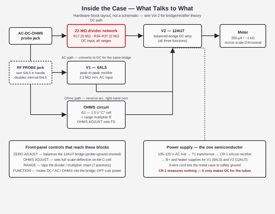
Hardware behind the ohms reading, tying back to §4’s block diagram: on OHMS, FUNCTION disconnects the external probe divider entirely and inserts B1 (the C-cell) plus the RANGE switch’s tapped multiplier resistor in series with whatever the probe and ground leads are clipped across. The resulting current through the unknown resistance develops a voltage drop that the 12AU7 bridge reads exactly as it would a DC input — which is why OHMS shares the same active devices and the same accuracy class as the DC function rather than needing a separate measuring circuit. OHMS ADJUST, done with the leads shorted (zero external resistance, maximum current from B1), sets that condition to read full scale; as B1 ages and its internal resistance climbs, OHMS ADJUST has less range to compensate with, and the point where it can no longer reach full scale is the unambiguous signal to replace the cell (Vol 5 covers replacement and the corrosion risk a leaked cell poses to the clamp and nearby PCB traces).
3.9 Zero-Center: the “DC Galvanometer” Mode
Every DC range on this instrument doubles as a center-zero null meter — Simpson’s manual calls it the “D.C. Galvanometer” mode, and it’s one of the two features (alongside the 22 MΩ input) that distinguishes a good VTVM from an adequate one on a tube-service bench.
With ZERO ADJUST balancing the bridge to the dial’s “−0+” mark at rest, the meter deflects left of center for one DC polarity and right of center for the other, reading a balance point rather than an absolute value. On the 1.5 V range specifically, that gives a calibrated 0.75-0-0.75 V null meter — useful precisely because a null reading (find where the deflection crosses zero) is far more sensitive and far less dependent on the meter’s own linearity than reading an absolute deflection would be.
The classic application is FM-discriminator alignment: a discriminator’s whole job is to output zero volts at the exact center frequency and swing positive/negative either side of it, so aligning one means finding the tuning-slug position that puts the meter dead on zero-center — a task the 311/311-2’s built-in galvanometer mode does natively, no extra fixture required. The same zero-center mode is useful more broadly for any balance/null bench task: matching two DC levels, finding a bridge-circuit balance point, or centering a ratio-detector output.
3.10 Extending the Range: HV and RF Probes
Two accessory probes extend the 311/311-2 well past what its front-panel ranges alone would suggest — one for DC voltage headroom, one for RF bandwidth.
3.10.1 kV HV Probe (0732)
Part 0732, rated 0 to 30,000 V DC. It contains a multiplier resistor that does two things at once: it raises the instrument’s total DC input resistance to 2,200 MΩ (§4), and it multiplies whatever the RANGE switch’s face value reads by ×100:
Table 10 — whatever the RANGE switch's face value reads by ×100
| RANGE switch position | Reading with HV probe fitted |
|---|---|
| 15 V | 0–1,500 V |
| 50 V | 0–5,000 V |
| 150 V | 0–15,000 V |
| 500 V | 0–50,000 V (full-scale marking) |
⚠ Danger — the arithmetic full-scale marking on the 500 V range with the probe fitted is 50,000 V, but Simpson’s own manual warning caps safe operating voltage at 30,000 V — do not exceed 30 kV with this probe regardless of what the dial arithmetic implies is available. High-voltage probe work of any kind follows the mains/HV bench-discipline rules in
_shared/legal_ethics.md— one-hand rule, bleed any HV capacitance before reaching in, respect the probe’s own kV rating, and never assume a “cold” HV circuit stays that way.
3.10.2 RF/HF Probe (0731 / 0174)
The RF probe’s part number and top frequency changed between revisions — another spec that doesn’t carry over cleanly from the 311 to the 311-2:
Table 11 — carry over cleanly from the 311 to the 311-2
| Revision | Probe part # | Frequency range | Other specs |
|---|---|---|---|
| 311 (original) | 0731 | Flat ±5 % from 50 Hz to 100 MHz | 0–150 V RMS / 0–400 V p-p, 10 pF input capacity, short built-in ground lead |
| 311-2 | 0174 | 10 kHz to 250 MHz | Not detailed beyond frequency range in the 311-2 manual as read for this dive |
Both probes plug into the front-panel RF PROBE jack (§2), contain their own 6AL5 (§5), and automatically disable the instrument’s internal AC rectifier when inserted — so at RF the rectification happens right at the test point rather than at the end of a cable run, which is what makes useful readings possible up past 100 MHz in the first place. The 311-2’s 0174 probe’s substantially higher top frequency (250 MHz vs. the original’s 100 MHz) tracks the same PCB-era bandwidth improvement that widened the internal AC frequency response in §6.
3.11 Physical Specifications
Everything measurable about the box itself, gathered in one table — mostly relevant when planning bench space, packing the unit for transport, or sanity-checking a “is this really a 311” listing against a seller’s photos:
Table 12 — seller's photos
| Property | Value | Confidence |
|---|---|---|
| Case | Metal, carry handle, hinged/fixed per era | CONFIRMED |
| Dimensions | 7½ in H × 5⅝ in W × 4½ in D | CONFIRMED |
| Weight, net | 4½ lb | CONFIRMED |
| Weight, shipping | 6 lb | CONFIRMED |
| Construction (311-2) | Printed-circuit-board — “most component parts mounted on a PCB” | CONFIRMED |
| Construction (311, original) | Manual text suggests an early move toward PCB assembly | CONFIRMED (311 text) |
| Line power | 105–125 V AC, 50/60 Hz | CONFIRMED |
| Power consumption | 5 W | CONFIRMED |
| Case grounding | 3-wire line cord ties the metal case to safety ground | CONFIRMED |
| Pilot lamp | L1, “cloudy-clear,” between GROUND and INPUT jacks | CONFIRMED |
| Original list price | Not found in any primary catalog read for this dive | [NOT FOUND] |
| Used-market price (present day) | Roughly $35 (secondary listing reference point) | [LIKELY, secondary] |
⚠ Danger — the case being tied to line safety ground via the 3-wire cord means the chassis is at ground potential relative to the AC mains — Simpson’s own manual specifically warns to exercise care when measuring anything referenced to line voltage, since an ungrounded or floating measurement setup elsewhere on the same bench can put the “grounded” instrument case at an unexpected potential relative to a different piece of gear. Standard bench-safety discipline from
_shared/legal_ethics.mdapplies whenever this instrument and another mains-powered piece of gear share a test point.
3.12 Inside the Case — Construction and Layout
The 311-2 is printed-circuit-board construction — “most component parts mounted on a PCB,” per its own manual — a step up from the original 311’s more traditional point-to-point/terminal-strip build, though the 311’s own manual text suggests it too was already moving toward PCB assembly by 1958–1962. Everything on the front panel (§2) routes back to that one board: the 22 MΩ divider chain, the 6AL5 and 12AU7 sockets, the C-cell clamp for B1, the power transformer T1 and CR-1, and — reachable through the case rather than the front panel — the calibration pots that trim the bridge (R20 DC CAL, R21 AC CAL, R29 ZERO SET, R32 AC contact-potential) that Vol 5 covers in the full recalibration sequence.
No hotlinkable, verified photo of a 311-2’s actual internals turned up during research for this dive — forum threads exist (Antique Radio Forums) but weren’t cleared for direct embedding here. Until Jeff’s own unit is opened and photographed, the block diagram in §4 stands in for a real internals shot; treat it as a wiring-logic map, not a to-scale physical layout.
3.12.1 Accuracy Classes in Practice
Two accuracy figures cover essentially everything this instrument reads, and it’s worth translating them into real numbers rather than leaving them as abstract percentages:
Table 13 — into real numbers rather than leaving them as abstract percentages
| Function | Stated accuracy | On the 15 V DC range, that’s ± | On the 1500 V DC range, that’s ± |
|---|---|---|---|
| DC volts | ±3 % of full scale | 0.45 V | 45 V |
| AC volts (RMS) | ±5 % of full scale | 0.75 V | 75 V |
| Ohms | ±3° of arc | (arc-dependent — not a flat percentage; tightest near mid-scale, widest near the arc ends) | — |
The “of full scale” qualifier matters more than it looks: accuracy is a fixed fraction of the range’s top end, not of the actual reading, so a small reading taken on a needlessly large range carries a much bigger relative error than the same physical voltage read on a range where it sits closer to mid-scale or full scale. Reading 2 V on the 1500 V range, for instance, carries a ±45 V absolute error budget that swamps the reading itself — the practical rule inherited from every analog meter of this design era is pick the lowest range that doesn’t pin the needle, never the largest range “to be safe.” Vol 4 covers range-selection procedure in full.
3.13 Common Confusions Corrected
Enough secondhand write-ups of this instrument get the hardware wrong that a short, explicit recap earns its place here — five specific claims to watch for, and what the manuals actually say:
Table 14 — its place here — five specific claims to watch for, and what the manuals actually say
| Claim seen in the wild | What’s actually true |
|---|---|
| ”11 MΩ DC input” | 22 MΩ, on all ranges, both revisions — Simpson’s own manual text, verbatim, twice. 11 MΩ is the generic other-brand VTVM figure. |
| ”12AU7/12AX7 dual triode front end” | 12AU7 only. No 12AX7 anywhere in this instrument. |
| ”6AL5 bridge circuit” | The 6AL5 is the AC/peak-to-peak rectifier. The 12AU7 is the bridge. |
| ”Late FET-input 311 units exist” | No FET-input 311 exists. The FET/solid-state Simpson is the separate Model 313. |
| ”Ohms battery is a D cell” | It’s a 1.5 V “C” cell (B1, part 1-111801). |
3.14 Cross-Bench Context
The 311-2’s headline hardware facts, gathered in one place for quick reference against its bench mate:
- 22 MΩ DC input, all ranges — versus a typical ~11 MΩ VTVM, and versus the loadable 20 kΩ/V Simpson 260 this instrument is built to out-class on high-impedance nodes.
- All-tube front end — 6AL5 rectifier + 12AU7 balanced bridge, one silicon diode (CR-1) confined to the power supply. No FET, no 12AX7.
- 200 µA / ~1 kΩ custom movement, mirror scale, four arc families (RMS, P-P, ohms, DC zero-center).
- Zero-center “D.C. Galvanometer” mode on every DC range — a null-meter capability the B&K Dynamatic 375 doesn’t share the same way, and worth reaching for specifically when an alignment task calls for a balance point rather than an absolute reading.
- 30 kV HV probe and up-to-250-MHz RF probe extensions — both genuine accessory capability, not front-panel range tricks.
Vol 4 picks up from here with operating procedure and probe technique; Vol 6 puts this instrument’s numbers side by side with the B&K 375’s for the two-VTVM cross-check bench, and works through where the two units are expected to agree closely, where a small systematic offset between them is normal rather than a fault, and what a real disagreement between the two on the same node should make you suspect first — a drifted divider resistor on one side, a soft tube, or a genuinely bad connection.
The RF PROBE jack visible in the control-panel photograph (§2) is easy to overlook next to the two large knobs and the range/function switches, but it’s the single detail that most separates this instrument from a generic bench VTVM: a dedicated, purpose-built accessory path that moves the AC rectifier out to the test point specifically to chase bandwidth the internal circuit can’t reach through a probe cable. Between the 22 MΩ DC input, the zero-center galvanometer mode, and the RF probe extension, the 311/311-2 punches well above what its compact, 4½-pound case suggests on first glance.
Sources
Primary (read in full, page-by-page):
- Simpson Electric Co., Operator’s Manual — Vacuum Tube Voltmeter Model 311-2, © 1966 (part 5-110700). https://www.simpson260.com/downloads/simpson_311-2_user_manual.pdf
- Simpson Electric Co., Operator’s Manual — Vacuum Tube Voltmeter Model 311, © 1958 (printing 1-62-JM-BL-Rev.1). https://simpson260.com/downloads/simpson_311-1_user_manual.pdf
- Simpson 311-2 manual mirror: https://archive.org/details/Simpson_311-2_VTVM
- Manual index (BAMA): https://bama.edebris.com/manuals/simpson/311-2
Secondary / corroboration:
- Nuts & Volts, “Vintage Tek: The Vacuum Tube Voltmeter” — https://www.nutsvolts.com/magazine/article/vintage-tek-the-vacuum-tube-voltmeter
- Radiomuseum — Simpson VTVM family (312/303 context): https://www.radiomuseum.org/r/simpson_vacuum_tube_volt_ohmmete.html ; https://www.radiomuseum.org/r/simpson_vacuum_tube_voltmeter_303.html
- Simpson 313 Solid-State (FET) VOM — ManualsLib product page: https://www.manualslib.com/products/Simpson-313-Solid-State-Vom-14060996.html
- Antique Radio Forums threads (internals/repair): 311 — https://antiqueradios.com/forums/viewtopic.php?t=329645 ; 311-3 — https://antiqueradios.com/forums/viewtopic.php?t=84636
- Recycled Goods 311 listing (source of the front-panel/dial/whole-unit photographs used in this volume): https://recycledgoods.com/simpson-311-vacuum-tube-volt-ohmmeter/