Simpson Model 311-2 VTVM · Volume 4
Simpson 311-2 — Vol 4: Using It — Operating Procedure, Probes & Safety
Four knobs, three zero adjustments, and one rule that never changes: short it and re-zero before you trust the needle.
This volume is the operator’s card — what to do, in order, with hands on the instrument. Vol 2 covers why the balanced bridge, the 6AL5 rectifier, and the ohms circuit behave the way they do; Vol 3 covers what every control and jack physically is. Here we only care about procedure: power on, zero, measure, and don’t get hurt doing it.
The 311-2’s entire front panel is four controls and three jacks (Vol 3 §2 has the full parts list). For this volume, the two that matter most are the pair Simpson calls the “balancing controls” — ZERO ADJUST and OHMS ADJUST — because getting the order of operations right around them is the single biggest determinant of whether a reading on this meter is trustworthy.
Note — Photos in this volume are of an original Simpson 311, not the 311-2 in hand. The 311-2’s PCB revision kept the same case, panel layout, and control set, so the procedure described here is identical for both — only the internal construction changed (Vol 3 §1).
4.1 Before You Touch a Test Point
4.1.1 Power-on and warm-up
The 311-2 is a tube instrument — the 12AU7 balanced-bridge amplifier and the 6AL5 rectifier (Vol 2 §1) both need their cathodes up to temperature and their operating points settled before the bridge balance is stable. Simpson’s own calibration procedure specifies a minimum 1-hour warm-up before any calibration step is performed, and the same physics applies to ordinary measurement: a cold 311-2 will drift as it warms, and a zero set in the first few minutes will not hold.
Table 1 — Power-on and warm-up
| Step | Action | Why |
|---|---|---|
| 1 | Function switch to OFF before connecting the line cord | OFF is a physical power-off position on this switch, not just a “no measurement” position (Vol 3 §2) |
| 2 | Plug in the 3-wire line cord | See §9 below before you do this near any live chassis |
| 3 | Function switch to any position other than OFF | Pilot lamp L1 (between the GROUND and INPUT jacks) lights; tubes begin heating |
| 4 | Let the instrument sit, powered, undisturbed, for at least an hour for anything precision-sensitive | Matches Simpson’s own cal-procedure warm-up; shorter warm-ups are fine for a rough go/no-go check but will drift under a demanding measurement |
| 5 | For quick bench checks (continuity, rough voltage sanity) | A 5–10 minute warm-up is a reasonable practical minimum — but re-zero immediately before the reading, not after |
Note — The scaffold notion of “re-zero every couple of months” is not a documented Simpson maintenance interval — Simpson’s primary manuals do not specify one. The manual’s actual instruction is re-zero per range/function change, which is a per-measurement discipline, not a calendar one. Re-calibration (the internal pots in Vol 5) is the calendar-driven task; zeroing is not.
Jeff’s bench pairs the 311-2 with the B&K Dynamic 375 VTVM for cross-checks. Both instruments need independent warm-up before their readings are compared — a warm 375 and a cold 311-2 will disagree for reasons that have nothing to do with either instrument’s calibration. Give both the full hour before trusting an agreement (or disagreement) between them.
4.1.2 Mechanical zero
Before power is ever applied, the meter movement’s resting position should read exactly 0 on every arc with no current flowing through it at all. This is a purely mechanical adjustment, independent of the electronics:
- With the instrument unpowered (or on the OFF position), look at the pointer against the scale.
- If it does not rest exactly on the leftmost “0” mark, use the small slotted screw under the scale (visible just below the dial glass) to rotate the movement’s zero-set spring until the pointer sits on 0.
- This should need doing rarely — a mechanical zero that has drifted usually indicates the instrument was dropped or jarred, not routine aging.
Mechanical zero and the electrical ZERO ADJUST knob (next section) are two different things measuring two different errors — do not confuse them. Mechanical zero corrects the movement itself; ZERO ADJUST corrects the balance of the electronic bridge feeding it.
4.1.3 Electrical ZERO ADJUST — the one habit that matters most
This is the adjustment that governs every single reading this instrument will ever produce, and it is also the step most often skipped by an operator in a hurry. Get this ritual automatic:
- Short the probe tip to the ground clip. Touch the AC-DC-OHMS probe tip directly to the alligator clip on the GROUND lead (or clip both to the same point), so the instrument sees zero input.
- Set the function switch to whichever mode you’re about to measure in (−DC, +DC, AC, or OHMS) and the range switch to whatever range you intend to use.
- Rotate ZERO ADJUST until the pointer sits exactly on 0.
- Remove the short and proceed with the measurement.
⚠ Danger — Re-zero on every range change and every function change — no exceptions, and especially crossing AC ↔ DC. The bridge’s zero balance point shifts with the switching contacts and the electrical environment each position presents; a zero set on the 1.5 V DC range does not carry over to the 500 V DC range, and it especially does not carry over from DC to AC or back. A stale zero doesn’t fail loudly — it just quietly offsets every subsequent reading by a fixed error that looks exactly like a real measurement.
Why AC↔DC is the worst offender: Simpson’s own manual documents an “appreciable zero shift” specifically when switching between AC and DC functions, corrected at the factory by an internal contact-potential trimmer (R-32, on the calibration side of the instrument — see Vol 5). That factory trim gets the nominal shift out, but it does not eliminate the operator’s obligation to re-zero on the front panel every time — R-32 sets a baseline; ZERO ADJUST is still the per-measurement correction.
The SVG in §12 below builds this “what probe, what setting, and did you re-zero” logic into a single decision aid — worth keeping open next to the bench the first several times you use this instrument.
4.2 The Standard Test Leads
Before working through each measurement mode, it’s worth knowing exactly what’s in your hands. The 311-2 ships with two leads, and one of them is more clever than it looks:
- GROUND lead — a banana plug on one end for the front-panel GROUND jack, an insulated crocodile/alligator clip on the other. This is the return path; it does the same job the black COM lead does on any other meter.
- AC-DC-OHMS probe — a banana plug for the front-panel INPUT / AC-DC-OHMS jack on one end, a pointed metal test-probe tip on the other. This is the lead that changes behavior mid-measurement.
4.2.1 The probe body’s slide switch
Partway down the probe’s insulated handle is a slide switch with two positions, and its position is what actually determines whether the ~1 MΩ DC isolating resistor (R6 in the 311-2’s parts list, Vol 3 §4) is in the circuit:
Table 2 — Partway down the probe's insulated handle is a slide switch with two positions, and its position is what actually determines whether the ~1 MΩ DC isolating resistor (R6 in the 311-2's parts list, Vol 3 §4) is in the circuit
| Slide switch position | What’s connected | Used for |
|---|---|---|
| AC/OHMS | Direct connection, tip to the instrument’s input — no series resistor | AC volts, OHMS |
| DC | Series isolating resistor (~1 MΩ) switched into the tip | DC volts |
This single mechanical switch is why the same physical probe serves all three measurement functions — the electronics behind the INPUT jack don’t change, only what’s between the tip and that jack. Get in the habit of checking the slide switch position before every measurement, the same way you check the front-panel range and function switches — a probe left on DC when you meant to read AC will still give you a plausible-looking (if slightly different, due to the added series resistance interacting with input capacitance) number, which is a worse failure mode than an obviously wrong one.
4.2.2 The S-hook tip
The 311 introduced a “new style” probe tip with a specially designed S-hook — a small hooked profile molded into the metal tip that lets you hang the probe on a test point (a terminal lug, a resistor lead, a tube-socket pin) and let go, rather than holding the probe steady with one hand while reading the meter with your eyes. This matters more than it sounds: freeing a hand while working inside a live or recently-live tube chassis is exactly the situation the one-hand rule (§9.2) is built around, and a probe that can hook and hold itself in place is a genuine safety feature, not just a convenience one.
Note — The S-hook works best on a horizontal lug or terminal where gravity keeps the hook engaged. On a vertical wire or a smooth round pin it can slip — don’t rely on it to hold a probe in a genuinely hazardous location; use it for hands-free reading at low-to-moderate voltages, and hold the probe conventionally for HV or awkward-geometry test points.
4.3 Measuring DC Volts
4.3.1 Setup and polarity
DC volts is the 311-2’s core measurement — the reason a 22 MΩ (Vol 2 §2) grid-input instrument exists at all, versus reaching for a loadable 20 kΩ/V VOM like the Simpson 260.
Table 3 — Setup and polarity
| Item | Setting |
|---|---|
| Probe | AC-DC-OHMS probe, slide switch set to DC (switches the ~1 MΩ series isolating resistor into the tip — Vol 3 §4) |
| Function switch | −DC or +DC depending on the polarity of the point under test relative to ground |
| Range switch | Start on the highest DC range (1500 V) if the voltage is unknown, then step down |
| Ground lead | Clipped to circuit common / chassis ground |
The −DC / +DC split exists because the meter movement is polarized — current has to flow through it in one direction to deflect the pointer up-scale. Rather than force the operator to observe polarity with a rectifier trick (as the AC path does), Simpson gives you two DC function positions that internally reverse the meter connection:
- −DC: for probing negative-going points relative to the ground lead (classic case: a tube’s grid-leak bias voltage, which sits negative relative to cathode/ground).
- +DC: for probing positive-going points (B+ rails, plate voltages, most positive supply rails).
Note — If you don’t know the polarity of the point you’re about to probe, start on −DC. A positive voltage on the −DC position simply pins the needle hard left (below 0, into the stop) rather than deflecting it usefully — annoying but harmless, and an unambiguous signal to flip to +DC. Guessing wrong the other way (a large negative voltage on +DC) does the same thing in the other direction. Neither guess risks the instrument; it’s purely a readability problem, not a safety one, as long as the voltage itself is within the range switch’s rating.
4.3.2 Range selection and reading
The 311-2 offers 7 DC ranges, full scale 1.5 / 5 / 15 / 50 / 150 / 500 / 1500 V, reading direct to 1500 V and extendable to 30,000 V with the HV probe (§6.2). Choose the lowest range that keeps the pointer on-scale — reading near mid-scale on a well-chosen range gives better resolution than reading near the bottom of an oversized range.
Table 4 — Range selection and reading
| Range switch position | Full-scale DC | Typical use |
|---|---|---|
| 1.5 V | 1.5 V | Bias voltages, small signal levels, precision null work |
| 5 V | 5 V | Grid bias, low-level supply rails |
| 15 V | 15 V | Filament/heater DC, small regulator outputs |
| 50 V | 50 V | Screen-grid supplies, low-voltage B+ taps |
| 150 V | 150 V | Common tube-circuit B+ taps |
| 500 V | 500 V | Plate supplies on many tube circuits |
| 1500 V | 1,500 V | HV supplies within direct-read range |
Accuracy is ±3 % of full scale on DC — quote your reading as, for example, “142 V ±3 % of the 150 V range (±4.5 V),” not “142.0 V.” The percentage-of-full-scale accuracy spec is a reminder to pick the range that puts your reading well up-scale: a 20 V reading on the 500 V range carries a ±15 V error band, while the same 20 V read on the 50 V range carries only ±1.5 V.
4.3.3 Zero-center (“D.C. Galvanometer”) mode for nulls
Any DC range can be used in a zero-center mode — useful whenever the task is balancing two voltages against each other rather than measuring one absolutely, such as FM-discriminator alignment where the goal is to find the point where a differential output crosses zero.
- On the 1.5 V range, zero-center mode reads 0.75-0-0.75 V — the needle sits at the physical center of the scale with no input and swings left or right of center as the differential goes negative or positive.
- The same principle scales to the other ranges (each becomes a ±half-full-scale null meter).
- Setup is otherwise identical to normal DC use: probe on DC, function switch to −DC or +DC per the manual’s zero-center procedure, ZERO ADJUST re-centered with the probe shorted before starting the null search.
Note — Zero-center/null work is exactly the kind of measurement where the ZERO ADJUST discipline in §1.3 matters most — a null-search that starts from a mis-zeroed center point will converge on the wrong balance condition and look perfectly confident doing it.
4.4 Measuring AC Volts
4.4.1 RMS (black arcs) vs. peak-to-peak (red arcs) — read the right one
The meter face carries two independent AC scale families, and picking the wrong one for the waveform in front of you produces a plausible-looking but wrong number:
Table 5 — The meter face carries two independent AC scale families, and picking the wrong one for the waveform in front of you produces a plausible-looking but wrong number
| Arc color | Calibration | Valid for | Ranges (311-2) |
|---|---|---|---|
| Black | RMS | Sine waves only | 1.5 / 5 / 15 / 50 / 150 / 500 / 1500 V RMS |
| Red | True peak-to-peak | Any waveform (sine, square, sawtooth, pulse, noise) | 4 / 14 / 40 / 140 / 400 / 1400 / 4000 V p-p |
The mechanism behind this split is in Vol 2 §3: the internal 6AL5 rectifies the incoming AC into a proportional DC via a peak-to-peak (voltage-doubler) topology, and the black RMS arcs are simply the p-p scale re-marked with a fixed sine-wave RMS-to-p-p conversion factor baked into the arc spacing. Feed the 311-2 a square wave or a pulse train and read the black arc, and the number will be internally consistent and completely wrong for that waveform’s actual RMS value — the instrument has no idea the waveform isn’t a sine, it’s just reading the peak-to-peak voltage through a fixed conversion. Read black only for sine, red for anything else.
Note — The 311’s original p-p endpoints (4.2 / 14 / 42 / 140 / 420 / 1400 / 4200 V p-p) differ slightly from the 311-2’s (4 / 14 / 40 / 140 / 400 / 1400 / 4000 V p-p) — a small recalibration between revisions, not a functional difference. If you’re cross-referencing an original-311 manual against a 311-2 unit, use the 311-2’s own numbers.
Setup for AC volts:
Table 6 — Setup for AC volts
| Item | Setting |
|---|---|
| Probe | AC-DC-OHMS probe, slide switch set to AC/OHMS (direct connection, no series isolating resistor — Vol 3 §4) |
| Function switch | AC |
| Range switch | Highest range first if magnitude unknown, then step down |
Accuracy is ±5 % of full scale on AC (roughly the guitar-string-precision worse cousin of the DC spec — expect more slop on AC than DC).
4.4.2 Frequency response — know where the flat band ends
The 311-2 substantially widened AC bandwidth over the original 311, but it is still not flat to daylight:
Table 7 — The 311-2 substantially widened AC bandwidth over the original 311, but it is still not flat to daylight
| Range | 311-2 frequency response |
|---|---|
| 1.5 / 5 / 15 / 50 V | ±5 % from 30 Hz to 1 MHz |
| 150 V | to roughly 500 kHz (tolerance not separately stated in the manual excerpt read for this doc) |
| 500 V | ±10 % to roughly 500 kHz |
Compare against the original 311’s flatter-but-narrower 30 Hz–100 kHz within ±5 % — the 311-2’s PCB-era front end is the meaningfully better AC instrument at RF-adjacent frequencies, on the lower-voltage ranges specifically. Above these ceilings, use the RF probe (§6.1) rather than trusting the internal rectifier — that’s precisely the accessory Simpson built to move the rectification point out to the signal, ahead of cable and internal-wiring loss.
4.4.3 The AC↔DC zero shift, in practice
Covered in principle in §1.3, but worth restating here because AC measurement is where operators get bitten by it most: switching the function switch from DC to AC (or back) shifts the bridge’s zero point by a documented, nontrivial amount. Re-zero is not optional after this switch — it is the single most common source of a “my 311-2 disagrees with my B&K 375” moment, and it’s a procedural error, not an instrument fault.
4.5 Measuring Resistance (OHMS)
4.5.1 The battery test is built into the procedure
Ohms on the 311-2 works by inserting the instrument’s own internal 1.5 V “C” cell (B1) in series with the unknown resistance and the range-multiplier network, then reading the resulting current on a dedicated ohms arc (Vol 2 §4). Because the reading depends on that battery’s actual voltage, every ohms measurement session starts with a battery check that doubles as the OHMS ADJUST calibration step:
- Probe on AC/OHMS (same slide-switch position as AC — no series isolating resistor).
- Function switch to OHMS.
- Range switch to whichever ×multiplier range you intend to use.
- Short the probe tip directly to the ground clip (the ohms equivalent of the ZERO ADJUST short in §1.3, but here it sets full-scale, not zero — ohms reads backward, right-to-left).
- Rotate OHMS ADJUST until the pointer reaches the “0 Ω” full-scale mark.
Note — If OHMS ADJUST cannot reach the 0 Ω mark with the leads shorted, the internal “C” cell is dead — replace it before trusting any resistance reading. This is diagnostic, not cosmetic: a weak-but-not-dead battery will let OHMS ADJUST reach full scale but leave less trim range for compensating normal aging, so a battery that needs the knob near its end-stop to zero is also worth replacing preemptively.
4.5.2 Range table and reading
Table 8 — Range table and reading
| Range switch | Center-scale value | Notes |
|---|---|---|
| ×1 | 10 Ω | |
| ×10 | 100 Ω | |
| ×100 | 1,000 Ω (1 kΩ) | |
| ×1K | 10 kΩ | |
| ×10K | 100 kΩ | 311-2 manual shows this row inconsistently as “1 megohm” — treat as a manual typo; use 100 kΩ |
| ×100K | 1 MΩ | |
| ×1M | 10 MΩ |
Reading = arc value × range multiplier. A pointer resting at the “5” graduation on the ×10K range reads 5 × 100 kΩ = 500 kΩ. Accuracy is ±3° of arc, not a percentage — meaning the error is roughly constant in scale-angle terms and therefore worst (as a percentage of the reading) at both ends of the arc, best near mid-scale. As with voltage ranges, pick the multiplier that lands your reading near mid-arc rather than jammed against either end.
⚠ Danger — Never measure resistance on a powered circuit. The internal battery assumes it’s the only voltage source in the loop; an energized circuit will add its own current through the movement, at minimum giving a nonsense reading and at worst driving the meter hard against a stop. De-energize and, for anything with filter capacitors, bleed them (§9.3) before reaching in with the ohms probe.
Note — Resistance measured in-circuit (component still soldered into a larger network) reads the parallel combination of the component and every other path around it — the classic VOM/VTVM caveat, not specific to this instrument. Lift at least one leg for a trustworthy reading on anything suspicious.
4.6 The Accessory Probes
The 311-2 was sold to be extended past its base voltage and frequency ranges with two purpose-built accessory probes. Both plug into dedicated jacks and both change what’s happening internally when they’re connected — understanding that matters for using them correctly.
4.6.1 RF / High-Frequency demodulator probe (Simpson 0174, to 250 MHz)
Table 9 — RF / High-Frequency demodulator probe (Simpson 0174, to 250 MHz)
| Spec | 311 (original, probe 0731) | 311-2 (probe 0174) |
|---|---|---|
| Frequency range | 50 Hz – 100 MHz, flat ±5 % | 10 kHz – 250 MHz |
| AC range covered | 0–150 V RMS / 0–400 V p-p | not separately re-stated in the 311-2 manual excerpt read for this doc |
| Input capacitance | 10 pF | not re-stated (assume comparable order) |
| Internal element | 6AL5 dual-diode full-wave rectifier in the probe handle | same family (6AL5 in probe handle, per Simpson’s design continuity) |
Mechanically and electrically, the RF probe moves the rectifier out to the signal source — instead of routing a high-frequency AC signal down a cable to the internal 6AL5 (where cable capacitance and lead inductance would roll off the response and pick up stray RF), the probe rectifies right at the tip and sends DC back down the cable to the bridge.
Setup and behavior:
- Plug the RF probe into the front-panel RF PROBE jack — a two-circuit phone jack that carries both the rectified signal and 6AL5 filament power out to the probe.
- Inserting the probe automatically disables the instrument’s internal AC rectifier — the 311-2 knows an RF probe is connected and routes around its own 6AL5, using the probe’s rectifier instead. This is a mechanical/electrical interlock at the jack, not a front-panel switch you set.
- Function switch stays on AC; range switch selection and arc reading (RMS black / p-p red) work exactly as in §4.
- The probe carries its own short ground lead — use it, don’t rely solely on the main GROUND lead, for the shortest possible ground return at RF.
Note — A fully probed-up 311/311-2 — main instrument plus RF probe plugged in — is effectively a three-tube instrument: the 12AU7 bridge, the internal 6AL5 (still powered on its filament but bypassed — it rectifies AC only, and sits idle on DC and ohms), and the RF probe’s own 6AL5 doing the actual demodulation. Keep that in mind for troubleshooting: an RF-probe measurement that misbehaves may be a probe-tube problem, not a main-chassis problem.
4.6.2 DC High-Voltage probe (Simpson 0732, ×100, to 30 kV)
Table 10 — DC High-Voltage probe (Simpson 0732, ×100, to 30 kV)
| Spec | Value |
|---|---|
| Multiplier | ×100 on the front-panel range markings |
| Total input resistance with probe fitted | 2,200 MΩ (vs. 22 MΩ bare) |
| Full-scale marking | 50,000 V |
| Maximum SAFE operating voltage | 30,000 V DC |
Table 11 — DC High-Voltage probe (Simpson 0732, ×100, to 30 kV)
| Range switch | Effective full scale with HV probe |
|---|---|
| 15 V | 0–1,500 V |
| 50 V | 0–5,000 V |
| 150 V | 0–15,000 V |
| 500 V | 0–50,000 V (full-scale marking) |
⚠ Danger — The 500 V range’s HV-probe marking reads to 50,000 V, but Simpson’s own published maximum SAFE operating voltage for the 0732 probe is 30,000 V. That gap exists because “full scale” is what the multiplier arithmetic produces (500 V × 100), not a safety-rated ceiling — the probe’s internal multiplier resistor and insulation are rated to 30 kV, full stop, regardless of what the arc happens to read past that point. Never intentionally work past 30 kV with this probe, and treat any reading north of 30 kV as “get away from this, don’t try to read it more precisely.”
The HV probe’s own internal multiplier resistor is what raises total input resistance to 2,200 MΩ (100× the bare 22 MΩ) — a good reminder that even at high voltage, this is still a vanishingly light load on whatever high-impedance HV supply you’re measuring, which matters on bleeder-less supplies where a loadable meter would itself pull the voltage down.
HV probe setup checklist:
- Confirm the circuit is de-energized before connecting the probe tip — HV probes are for reading a supply, not for hot-clipping onto one.
- Function switch to +DC or −DC per the supply’s polarity; range switch per the table above.
- Re-zero with the probe tip grounded (§1.3) — the HV probe’s added multiplier resistor is part of the measuring chain and its own zero offset should be nulled out before trusting the reading.
- Energize, read, and de-energize and bleed (§9.3) before disconnecting the probe.
4.7 Worked Examples: Six Measurements Start to Finish
Procedure reads differently in the abstract than it does with a specific test point in mind. The six walkthroughs below cover the measurement types this instrument was built for — read the one closest to what’s on your bench, or read all six to build the muscle memory for the re-zero habit before it becomes automatic.
4.7.1 Reading a tube’s plate (B+) supply
A common tube-radio service task: confirm the B+ rail feeding an output tube’s plate is near its design value.
- Function switch OFF, plug in, switch to +DC (B+ rails are positive relative to chassis in the overwhelming majority of tube circuits), warm up.
- Probe slide switch to DC.
- Estimate the expected voltage from the schematic (say, a nominal 250 V B+) and set the range switch to 500 V — one range up from a direct 250–500 V guess, so a higher-than-expected reading doesn’t pin the needle.
- Short probe tip to ground clip, ZERO ADJUST to 0.
- Clip GROUND lead to chassis; touch probe tip to the plate pin or a nearby B+ test point.
- Read the deflection against the 500 V arc — if it lands well below mid-scale (say, under 125 V), drop to the 150 V range and re-zero before re-reading for better resolution.
- Quote the result with its accuracy band: on the 150 V range, ±3 % of full scale is ±4.5 V — “228 V ±4.5 V,” not “228.0 V.”
4.7.2 Checking heater/filament AC and residual hum
Filament circuits run AC (or DC in some designs); a service tech often wants both the nominal AC level and a rough sense of ripple/hum riding on a DC filament supply.
- Probe slide switch to AC/OHMS; function switch to AC.
- For a straightforward 6.3 V AC heater winding, range switch to 15 V (comfortably above 6.3 V, keeps the reading well up-scale rather than pinned near a lower range’s top).
- Short and re-zero (§1.3) — AC zero is a different balance point than the DC zero used a moment ago in example 1, even on the same instrument, same session.
- Read the black RMS arc — heater AC is a clean sine wave off the power transformer secondary, so RMS is the correct arc here.
- For hum/ripple riding on a DC filament supply (some AC/DC and battery-eliminator designs), the AC function reads the AC component superimposed on the DC — but confirm against the schematic whether the design expects meaningful ripple at all before treating a nonzero AC reading as a fault.
4.7.3 Bench-testing a resistor before it goes back in the circuit
- Lift the resistor from the circuit entirely (at least one leg) — an in-circuit reading picks up every parallel path around it (§5).
- Function switch to OHMS; probe slide switch to AC/OHMS.
- Estimate the resistor’s marked value from its color code — say a 4.7 kΩ resistor — and pick the range that lands it near mid-arc: ×100 puts 4.7 kΩ well up the arc (center-scale on ×100 is 1 kΩ, so 4.7 kΩ reads 4.7× center, out in the compressed high-resistance end); ×1K (center 10 kΩ) puts the same reading at 0.47× center, closer to mid-arc in the more open part of the scale. Both keep the reading on-scale, but ×1K gives the better resolution for this value.
- Short the probe tip to the ground clip, OHMS ADJUST to the 0 Ω full-scale mark — this is the battery-test step (§5.1); if it won’t reach full scale, stop and replace the “C” cell before trusting anything that follows.
- Clip the leads across the resistor (polarity doesn’t matter for a plain resistor), read the arc, multiply by ×1K.
- Compare against the color-code value and the resistor’s tolerance band — a 4.7 kΩ ±5 % resistor reading 4.4–4.9 kΩ is in spec; well outside that band (with the leads confirmed good and the battery confirmed fresh via step 4) means replace the part.
4.7.4 FM-discriminator null with zero-center mode
A classic use of the zero-center (“D.C. Galvanometer”) mode from §3.3 — finding the exact tuning point where a discriminator’s differential DC output crosses zero.
- Function switch to +DC or −DC per the manual’s zero-center setup (the two triode-half outputs are being compared against each other, so absolute polarity convention matters less than consistency).
- Range switch to whichever range’s zero-center span comfortably brackets the expected swing — the 1.5 V range’s 0.75-0-0.75 V span is usually generous enough for discriminator work.
- Short and ZERO ADJUST to the physical center of the scale (not the left-hand “0” used for ordinary DC — zero-center mode puts 0 V input at the scale’s midpoint).
- Connect across the discriminator’s differential output, adjust the alignment slug or trimmer under test, and watch the needle — the null point is where the needle sits exactly at center with no adjustment overshoot in either direction.
- Because this is a balance/null measurement rather than an absolute-value one, the ±3 % full-scale DC accuracy spec matters less than the needle’s ability to repeat a center reading — confirm center-crossing repeats consistently before calling the alignment done.
4.7.5 RF probe reading a local-oscillator signal
- Plug the RF probe (0174) into the front-panel RF PROBE jack — this automatically routes around the internal 6AL5 (§6.1); no front-panel switch to set for this handoff.
- Function switch to AC (the RF probe still reports through the AC function — only the rectification point has moved to the probe tip).
- Range switch: start high, step down, same discipline as any unknown-magnitude measurement.
- Use the RF probe’s own short ground lead, clipped as close to the signal source’s local ground as the circuit allows — at RF, a long ground return picks up its own inductive drop and reads as signal.
- Confirm the frequency in question is within the probe’s stated range (10 kHz–250 MHz for the 311-2’s 0174 probe) before trusting the reading — above that, the probe’s own rolloff becomes the dominant error source, not the instrument.
- Read black (RMS, sine) or red (p-p, anything else) exactly as in §4.1 — the RF probe changes where rectification happens, not which arc is correct for the waveform.
4.7.6 HV probe reading a CRT anode / post-accelerator supply
The kind of measurement this probe exists for — vintage CRT-equipped gear (television sets, oscilloscopes) routinely runs anode supplies in the 10–25 kV range.
- De-energize the device under test and discharge the CRT anode through a 1 MΩ resistor and clip lead to chassis before doing anything else — a CRT anode supply stores real charge on the tube’s internal capacitance and stays dangerous well after power-off, independent of whatever the 311-2 is about to read (per
_shared/legal_ethics.md). - Plug the 0732 HV probe into the 311-2’s INPUT jack; probe slide switch position is not applicable to the HV probe body (it’s a purpose-built accessory, not the standard AC-DC-OHMS probe).
- Function switch to +DC (CRT anode supplies are positive relative to chassis); range switch to 500 V for the widest HV-probe span (0–50,000 V marking, 30,000 V safe ceiling — §6.2).
- Short and re-zero with the probe tip grounded.
- Only then bring the probe tip to the anode connection — following the manufacturer’s own HV-probe safety procedure (insulated shaft, adequate standoff distance, one-hand rule) rather than any shortcut.
- Read the deflection; if it’s reading anywhere past the 30 kV safety ceiling, back away rather than trying to resolve the number more precisely — that reading has already told you what you need to know (this supply is above the probe’s rated safe limit).
- After reading, de-energize and re-discharge the anode connection before disconnecting the probe.
4.8 Troubleshooting While Operating
Not every unexpected reading is a fault in the circuit under test — some are the 311-2 itself telling you something. These are operator-level checks; anything that points to an internal fault gets the full repair treatment in Vol 5.
Table 12 — Troubleshooting While Operating
| Symptom | Likely cause | What to check |
|---|---|---|
| Needle won’t reach 0 on ZERO ADJUST, probe shorted | Bridge badly out of balance — often a tube (12AU7) nearing end of life, or the AC contact-potential trim (R-32) badly off | If a fresh 12AU7 doesn’t fix it, this is a Vol 5 repair task, not an operator adjustment |
| Needle won’t reach the 0 Ω mark on OHMS ADJUST | Internal “C” cell exhausted (§5.1) — by far the most common cause | Replace the battery first; only chase the bridge if a fresh cell doesn’t fix it |
| Needle sluggish, slow to settle, or overshoots and creeps back | Instrument still warming up, or a tube (12AU7/6AL5) marginal | Give it the full warm-up (§1.1) before troubleshooting further; persistent sluggishness after warm-up is a Vol 5 tube-aging question |
| Reading jumps erratically with the probe held still | Poor ground connection, RF pickup on an unshielded lead, or (on DC) a probe slide switch left on AC/OHMS picking up AC hum on a DC node | Check the ground clip contact first, then the slide-switch position, then consider whether the test point is genuinely RF-noisy and needs the RF probe instead |
| Reading disagrees noticeably from the B&K 375 on the same node | Stale zero on one or both instruments (by far the most common cause), or one instrument still cold | Re-zero both independently, confirm both have had a full warm-up, then re-compare before suspecting a calibration fault |
| Needle pins hard against a stop immediately on contact | Wrong polarity (DC) or a voltage well beyond the selected range | Flip −DC/+DC or step up a range; pinning briefly does not damage the instrument, but don’t leave it pinned |
| OHMS reads near-zero on every range, leads not shorted | Actual short in the circuit under test, or a probe tip shorted to the ground clip inadvertently | Verify probe/ground routing before assuming a circuit fault |
4.9 Mains & Bench Safety
4.9.1 The 3-wire cord ties the metal case to earth — know what that means both ways
The 311-2 runs on 105–125 V AC, 50/60 Hz, 5 W, through power transformer T1 and a solid-state rectifier CR-1 (the instrument’s only semiconductor — Vol 2 §1). Its 3-wire line cord grounds the metal instrument case to the safety-ground (third) wire.
This cuts both ways for the operator:
- In your favor: the case itself is not a shock hazard under normal conditions — touching the 311-2’s chassis while it’s plugged into a properly grounded outlet is no different from touching any properly grounded appliance case.
- Against you: because the case is tied to safety ground, and the GROUND lead’s banana plug returns to that same case ground internally, the 311-2’s ground lead is not floating — it is bonded to building earth ground through the cord. Simpson’s own manual specifically warns to exercise care when measuring relative to line voltage for exactly this reason.
⚠ Danger — On any hot-chassis device (a classic AC/DC vintage radio or television whose chassis is directly connected to one side of the AC line, with no power transformer isolating it) clipping the 311-2’s grounded lead to the chassis can complete a direct short to the AC line through the instrument’s own safety ground — a real hazard to both the device under test and to you. Standard bench discipline for this class of vintage equipment (per the hub-level
_shared/legal_ethics.md) is an isolation transformer between the wall and the device under test whenever the device itself is not double-insulated or transformer-isolated — this reduces risk for any grounded test instrument connected to a hot chassis, the 311-2 included.
4.9.2 The one-hand rule
Above roughly 50 V, work with one hand — keep the other hand in a pocket or behind your back. This isn’t specific to the 311-2; it’s the standing rule for any HV/tube-era bench work in this project (_shared/legal_ethics.md), and it applies just as much to the meter’s own leads as to the circuit under test: a slipped probe at 500 V B+ is exactly the scenario the rule exists for. It matters even more with the HV probe (§6.2) in play, where the numbers involved are in the kilovolt range.
4.9.3 Bleed B+ before reaching in
Tube-circuit B+ supplies commonly carry substantial filter capacitance that stays charged well after power-off — this is true of the circuit under test, not the 311-2 itself (which has no user-serviceable HV internally beyond ordinary line-derived B+ for its own tubes). Before reaching into a tube chassis to move a probe, clip, or lead by hand:
- Power off and unplug the device under test.
- Discharge its filter capacitors through an appropriate bleeder resistor (never a direct dead-short with a screwdriver) before working inside.
- Only then reposition leads by hand inside the chassis.
4.9.4 Cross-reference
Full mains/HV/hazardous-materials bench discipline for this project lives in _shared/legal_ethics.md — GFCI at the bench, isolation transformers for hot-chassis gear, variac-based capacitor reforming, one-hand rule, and the hazardous-materials notes (PCB transformers, BeO heatsinks, asbestos resistors, old electrolytics) relevant to anything this vintage. Read it once per project, not just per instrument.
4.10 Between Sessions: Idle Care
The 311-2 doesn’t need much between sessions, but a few habits keep it ready to trust the next time it comes off the shelf:
- Leave the function switch on OFF when not in use. OFF is a genuine power-off position (§1.1), so there’s no standby drain and no reason to leave it on any measurement function between sessions.
- Don’t leave the internal “C” cell installed indefinitely if the instrument will sit unused for months. A dead alkaline or zinc-carbon cell left in a clamp is the classic slow-motion failure mode for this class of instrument — a leaked cell corrodes the holder and nearby traces (Vol 5 covers the repair). If the 311-2 is going into long-term storage, pull the battery; it’s a five-minute job to reinstall (observe polarity) versus a genuine corrosion repair if it leaks in place.
- Store leads coiled loosely, not kinked tight. The DC probe’s isolating resistor and the RF/HV probes’ internal components are all inside the probe handles — a sharply kinked cable is a mechanical stress on internal connections that a loose coil avoids.
- Cap or bag the RF and HV probe jacks if the accessories aren’t a permanent fixture on the bench, mostly to keep dust and metal shavings (a real hazard on any bench that also does chassis work) out of the RF PROBE phone jack’s contacts.
- An instrument that’s sat for a long time (months to years) deserves the full warm-up-and-re-zero ritual before its first reading is trusted again, and arguably a fresh look at the OHMS ADJUST battery test before anything else — an idle “C” cell self-discharges over time even without ever being loaded.
None of this replaces the periodic calibration-verification discipline in Vol 5 — idle care keeps the instrument ready to be used; calibration verification confirms it’s still accurate. They’re different questions with different cadences.
4.11 Quick-Reference: DON’Ts
Table 13 — Quick-Reference: DON'Ts
| Don’t | Why |
|---|---|
| Trust a reading without re-zeroing after a range or function change | Bridge zero shifts with switching — this is the single most common source of a wrong-but-confident reading |
| Read the black RMS arc on a non-sine waveform | RMS arcs are sine-calibrated; a square wave or pulse read there is wrong even though it looks precise |
| Measure resistance on an energized circuit | The internal battery assumes it’s the only source in the loop; line current through the movement gives nonsense or pins the needle |
| Trust an OHMS reading when OHMS ADJUST can’t reach 0 Ω | The internal “C” cell is exhausted — replace it first |
| Exceed 30 kV with the HV probe, even though the dial reads to 50 kV | 50 kV is arithmetic (500 V × ×100); 30 kV is Simpson’s actual safety ceiling for the probe |
| Clip the ground lead to a hot chassis without an isolation transformer | The 311-2’s ground lead is bonded to earth through its own 3-wire cord — a hot chassis can short straight to line through it |
| Skip warm-up before a precision measurement | The 12AU7 bridge and 6AL5 rectifier both drift while warming; Simpson’s own cal procedure specifies ≥1 hour |
| Reach into a tube chassis without bleeding B+ first | Filter capacitors hold a lethal charge well after power-off, independent of the 311-2 itself |
| Assume the DC probe’s series isolating resistor is engaged on AC/OHMS | The slide switch physically routes around it in that position — it’s a DC-only element |
| Compare an unzeroed 311-2 reading against the B&K 375 and call it a calibration disagreement | Re-zero both instruments independently first — a stale zero on either one masquerades as a real disagreement |
| Read resistance in-circuit and trust the absolute value | Every parallel path around the component under test is part of the reading; lift at least one leg for anything you actually need to trust |
| Guess the polarity of an HV point without stepping down from a known-safe indirect indication first (schematic, prior measurement, known circuit topology) | A wrong guess on −DC/+DC is harmless at bench voltages but at HV-probe territory the priority is knowing what you’re about to touch before the meter tells you, not after |
| Leave the RF probe plugged in and assume the internal 6AL5 is still doing the rectifying | Inserting the RF probe automatically routes around the internal rectifier — troubleshoot the probe’s own tube, not the main chassis, if RF readings misbehave |
4.12 Measurement Decision Aid
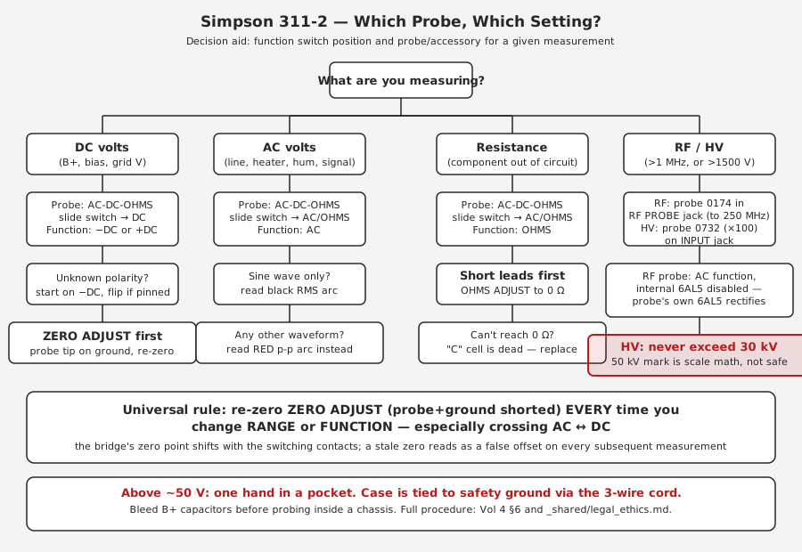
4.13 Reference: The Panel, for Orientation
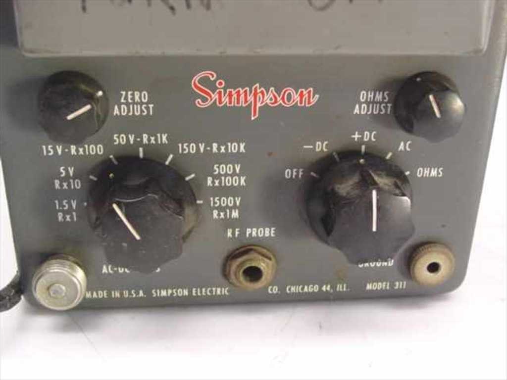
Every control named in this volume — ZERO ADJUST, OHMS ADJUST, the RANGE switch, the function switch, the RF PROBE jack — is visible in this photo in the same physical layout the 311-2 carries. Full identification of each control and jack, with part numbers, is in Vol 3 §2.
Sources
- Simpson Electric Co., Operator’s Manual — Vacuum Tube Voltmeter Model 311-2, © 1966 (part 5-110700). https://www.simpson260.com/downloads/simpson_311-2_user_manual.pdf — range tables, ohms battery (“size C” cell), zero-adjust/ohms-adjust procedure, warm-up and calibration sequence, AC/DC frequency response (Fig. 2), HF probe spec (0174), physical/electrical specs.
- Simpson Electric Co., Operator’s Manual — Vacuum Tube Voltmeter Model 311, © 1958 (printing 1-62-JM-BL-Rev. 1). https://simpson260.com/downloads/simpson_311-1_user_manual.pdf — 22 MΩ input, zero-center galvanometer mode, probe slide-switch (AC/OHMS vs. DC isolating resistor), RF probe (0731, §V), DC high-voltage probe (0732, §V), one-hand-rule-adjacent case-ground warning.
- Simpson 311-2 manual mirror: https://archive.org/details/Simpson_311-2_VTVM
- Manual index (BAMA): https://bama.edebris.com/manuals/simpson/311-2
- Recycled Goods, Model 311 listing (control-panel photo): https://recycledgoods.com/simpson-311-vacuum-tube-volt-ohmmeter/
- TestEquipment hub bench-safety doc:
_shared/legal_ethics.md— mains/HV/hazardous-materials discipline referenced throughout §9.