Simpson Model 311-2 VTVM · Volume 5
Simpson 311-2 — Vol 5: Calibration & Refurbishing
Rezero, recal, and the four failure modes that quietly steal a half-century-old VTVM's accuracy — none of which require a new schematic.
5.1 Scope of This Volume
Vol 3 covered what is inside the case; Vol 4 covered how to operate the instrument day to day. This volume covers keeping it accurate — the rezero discipline every session needs, the internal calibration-pot procedure Simpson specified for the 311-2’s printed-circuit-board revision, and the four refurbishing jobs that show up, in order of how often they actually bite an owner: warm-up zero drift, precision-resistor drift in the 22 MΩ divider, corrosion from the internal “C” cell, and tube aging after a 12AU7 swap. None of this is exotic work — a 311-2 is a two-tube (6AL5 + 12AU7), single-board instrument with four internal pots and a socketed battery. The goal here is to turn “it reads funny” into a specific, sourced fix rather than a guess.
Note — Everything below is sourced from Simpson’s own Operator’s Manual — Vacuum Tube Voltmeter Model 311-2 (© 1966, part 5-110700) and the earlier Model 311 manual (© 1958, printing rev. 1-62), both read page-by-page for this dive. Where a number is not in either manual it is flagged [UNCERTAIN] or [NOT FOUND] rather than invented. See Vol 1 §1 for the full provenance discussion and Vol 3 §1 for the 311 → 311-2 → 311-3 lineage.
5.2 Warm-Up, Drift & When to Recalibrate
5.2.1 Why a tube VTVM drifts at all
The 311-2’s measuring path is a balanced bridge built from the two triode halves of a single 12AU7 (Vol 2 §2). With no input applied, ZERO ADJUST balances that bridge so the meter sits at 0. Three things move that balance point over time:
- Heater/cathode warm-up. Cold tubes draw slightly different plate current in each half until the heaters and cathodes reach thermal equilibrium — the classic reason every tube instrument needs a soak before it’s trustworthy.
- AC↔DC switching. Different signal paths through the bridge (rectified-AC vs. raw DC) present slightly different loading/contact potentials, producing the “appreciable zero shift” Simpson’s own manual describes and specifically provides an internal pot (R-32) to trim out. [CONFIRMED]
- Long-run component aging. Tube emission sags, and the precision resistors in the divider network drift (§4 below) — both slow, both cumulative over years rather than minutes.
The balanced-bridge topology exists specifically to cancel (1): because both triode halves share one envelope, one heater supply, and one B+ rail, warm-up drift that is common to both halves cancels, and only the difference between the halves shows up as a zero shift. That’s why re-zeroing — not a full recalibration — clears the great majority of day-to-day drift. [CONFIRMED tube role/bridge topology — Simpson manuals; cancellation mechanism is standard balanced-bridge theory]
5.2.2 Warm-up discipline
Note — Simpson’s calibration procedure specifies at least 1 hour of warm-up before any cal adjustment is trusted. [CONFIRMED — 311-2 manual] Vol 4 already covers the operating warm-up habit (let it sit on, ZERO ADJUST re-checked before each reading session); this is the stricter figure for cal work specifically — don’t shortcut it because the meter “looks settled” after 10 minutes.
Routine practice, cheapest to most involved:
Table 1 — Routine practice, cheapest to most involved
| Situation | What to do | Why |
|---|---|---|
| Any session start | Power on, wait for warm-up, re-zero on the range/function you’ll use | Cancels common-mode heater drift (see above) |
| Switching AC↔DC | Re-zero again | Bridge loading differs between paths; Simpson calls this out explicitly |
| Switching ranges | Re-zero again | Divider tap changes the bridge’s operating point slightly |
| Zero won’t settle / drifts visibly while warmed up | Suspect a soft/gassy 12AU7 (§5) before touching the internal pots | A marginal tube looks like a cal problem but isn’t one |
| OHMS ADJUST can’t reach full-scale (“0 Ω”) | Battery is dead or corroded contacts (§6) — not a cal fault | Manual states this explicitly |
| Readings agree with a second VTVM at warm-up but drift apart over the session | Compare against the B&K 375 (cross-ref below) before assuming either is wrong | Confirms which unit actually drifted |
5.2.3 The power supply’s role in drift
It’s worth being explicit about one more drift contributor before moving on: the 311-2’s B+ and heater rails come from power transformer T1 and the single silicon rectifier CR-1 (750 mA, part 1-117943) — the instrument’s one semiconductor, and not a measuring element (Vol 2 §2, Vol 3 §4). CR-1 itself is solid-state and doesn’t meaningfully age the way a tube does, but the filter capacitor downstream of it (C5, §7 below) does — a tired C5 lets more ripple onto the B+ rail than Simpson designed for, and that ripple shows up as noise riding on the bridge’s zero point. If a unit’s zero is noisy rather than slowly drifting — jittering visibly at a mains-related rate rather than creeping in one direction over minutes — suspect the supply filtering before the tubes or the cal pots. This is a useful triage split: slow, one-directional drift during warm-up points at the tubes settling in; fast, periodic jitter points at the supply.
5.2.4 Recalibration cadence — what’s sourced and what isn’t
Simpson’s manual gives a procedure (warm up ≥1 h, then run the four-pot sequence in §3) but does not state a fixed calendar interval for routine recalibration. It calls for recal specifically after: a tube change (12AU7 or 6AL5), evidence the unit is out of tolerance against a known reference, or extended service/storage. A blanket “every couple of months” cadence is a reasonable bench habit but is [UNCERTAIN] — not a Simpson-specified number. Treat the cal-pot procedure as condition-triggered, not calendar-triggered, unless you’re running it against a lab-grade DC/AC standard often enough that a fixed interval actually makes sense for your shop. [manual procedure = CONFIRMED; fixed monthly interval = UNCERTAIN, not sourced]
5.3 The Internal Calibration-Pot Procedure
5.3.1 The four pots
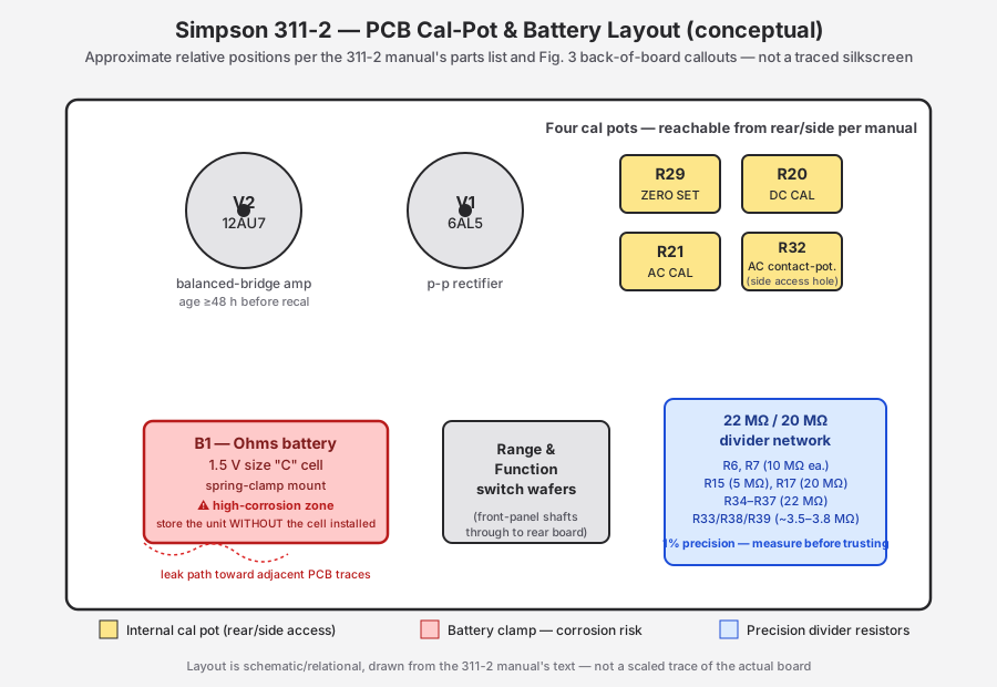
The 311-2’s printed-circuit-board layout puts four adjustment potentiometers on the board, reachable from the rear/side of the case (one, R-32, through a dedicated hole under the handle — no case opening required for that one alone). [CONFIRMED — 311-2 manual]
Table 2 — The four pots
| Designator | Function | Adjusts | Access |
|---|---|---|---|
| R29 | ZERO SET | Bridge balance / +DC↔−DC zero symmetry | Rear board, case open |
| R20 | DC CAL | DC-volts full-scale accuracy against a known DC reference | Rear board, case open |
| R21 | AC CAL | AC-volts full-scale accuracy against a known AC reference | Rear board, case open |
| R32 | AC contact-potential | Zero shift specifically when switching AC↔DC | Side access hole under handle — no disassembly |
Note — These four are distinct from the two front-panel controls covered in Vol 3/Vol 4 — ZERO ADJUST (routine per-session rebalancing, always available to the user) and OHMS ADJUST (routine ohms full-scale set, also always available). R29/R20/R21/R32 are the internal factory-cal trims; you reach for them only when front-panel ZERO ADJUST/OHMS ADJUST can no longer bring the instrument into tolerance, or after a repair that could have shifted the bridge (new tube, new divider resistor, recapped supply).
5.3.2 Test equipment needed before you start
Do not run this procedure “by feel.” Simpson’s own sequence is a comparison calibration — you’re trimming the 311-2 to agree with a known-good reference, not setting it to an absolute internal standard. You need:
Table 3 — standard. You need
| Reference needed | Used for | Substitute if you don’t have a cal lab |
|---|---|---|
| Known, stable DC voltage source near the range you’ll cal | R20 DC CAL | A bench DC power supply verified against a trusted DMM |
| Known, stable AC voltage source at 60 Hz near the range you’ll cal | R21 AC CAL | A Variac-fed transformer + trusted true-RMS DMM, or a signal generator + trusted AC meter |
| A second trusted meter to read the reference (not the 311-2 itself) | Both DC and AC cal steps | The sibling B&K 375 VTVM (cross-ref Vol 6), or a modern bench DMM |
| Shorted probe+ground lead | ZERO SET / probe-DC-zero steps | The 311-2’s own standard AC-DC-OHMS probe and ground lead |
⚠ Danger — The AC CAL and DC CAL steps below involve applying voltage to an open, powered instrument. The 311-2’s metal case is tied to the AC line’s safety ground via its 3-wire cord, but internal points are still live at line-derived and B+ potentials while the case is open. Follow the one-hand rule and the full bench-safety discipline in
_shared/legal_ethics.mdbefore opening the case on a powered unit.
5.3.3 The six-step factory sequence
Simpson specifies the following order for the 311-2. Each step depends on the one before it, so don’t skip or reorder:
- Warm up ≥1 hour with the case open and the unit powered on the bench, probe and ground lead connected and available.
- Set R29 (ZERO SET) so the +DC and −DC positions agree at zero — short the probe to ground, flip between +DC/−DC on the function switch, and trim R29 until both positions read the same zero. This is the core bridge-balance/polarity-symmetry adjustment.
- Probe DC-zero check — with the probe still shorted to ground, verify DC zero holds on the range(s) you use most; front-panel ZERO ADJUST should now need only a small trim, not a large one.
- AC zero (R32) — switch to AC with the probe still shorted; trim R32 to null the AC↔DC zero shift described in §2 above.
- DC cal against a known DC reference (R20) — apply the reference DC voltage to the probe, select the matching range, and trim R20 until the 311-2 agrees with the reference within tolerance.
- AC cal against a known AC reference (R21) — apply the reference AC voltage, select the matching range, and trim R21 until the 311-2 agrees within tolerance.
[Six-step sequence CONFIRMED — 311-2 manual]
Note — Steps 5 and 6 are where the ±3 % DC / ±5 % AC full-scale accuracy specs (Vol 1 §3, Vol 4 §2) actually get set. If the 311-2 has been reading consistently high or low against the B&K 375 across several ranges (not just one), R20/R21 drift — or the divider-resistor drift in §4 below — is a more likely cause than a bad tube.
5.3.4 Which ranges to check, and how many points
Simpson’s six-step sequence describes trimming against a known DC and a known AC reference — it does not specify a full multi-point linearity check across all seven DC ranges and all fourteen AC arcs (seven RMS + seven peak-to-peak, Vol 1 §3). In practice, a useful refurb-time check goes beyond the bare minimum the six steps require:
- Run the six-step sequence on the mid-range you use most (commonly the 15 V or 50 V DC range for general tube-circuit work), since that’s where R20/R29 get trimmed.
- After the cal-pot sequence, spot-check the other six DC ranges against the same reference source at a comparable percentage of full scale, without touching the pots again. Record each range’s error against the ±3 % DC spec.
- Do the same for AC, spot-checking a couple of the RMS ranges against the ±5 % AC spec.
- If one range checks out clean but a different range is well outside tolerance while the cal’d range is fine, the fault is most likely in that specific range’s divider tap or a range-switch contact issue (Vol 3 §4) — not something the four cal pots, which are shared across all ranges, can fix by themselves.
Note — This multi-range spot-check is not part of Simpson’s documented procedure — it’s good refurb practice layered on top of it, worth doing precisely because it catches range-specific faults (a bad switch contact, one drifted divider tap) that a single-range cal-pot trim cannot.
5.4 Precision Divider-Resistor Drift (the 22 MΩ/20 MΩ Network)
5.4.1 Why this matters more on a 311-2 than on most VTVMs
The 311-2’s headline spec — 22 MΩ DC input on all ranges, double the typical 11 MΩ VTVM figure (Vol 1 §3, Vol 2 §3) — is built from a chain of individually large precision resistors, not one part:
Table 4 — (Vol 1 §3, Vol 2 §3) — is built from a chain of individually large precision resistors, not one part
| Designator | Nominal value | Role |
|---|---|---|
| R6, R7 | 10 MΩ each | Probe/input isolation |
| R15 | 5 MΩ | Divider network |
| R17 | 20 MΩ | Divider network |
| R33, R38, R39 | ~3.5–3.8 MΩ each | Divider network |
| R34–R37 | 22 MΩ each | Divider network |
[CONFIRMED parts and values — 311-2 manual parts list / Vol 2 §3]
These are ±1 % precision parts by original spec, and their ratios to each other, not just their absolute values, set both the DC input impedance and the accuracy of every DC range. A carbon- composition or older carbon-film resistor at these multi-megohm values drifts upward with age far more than a low-value part does — the failure mode is well understood in vintage-test-gear circles: humidity and heat slowly increase resistance in high-value carbon parts over decades, and a half- century-old 311-2 has had the decades. [drift direction and mechanism = standard vintage-electronics knowledge; the specific part values above are CONFIRMED from Simpson’s manual]
Note — The 22 MΩ and 20 MΩ units (R34–R37 and R17) are the ones most worth measuring first — they’re both the largest values (proportionally most sensitive to drift) and the ones that directly set the headline 22 MΩ input spec Simpson built the instrument’s whole marketing claim around.
5.4.2 Measuring: in-circuit vs. pulled
Table 5 — Measuring: in-circuit vs. pulled
| Method | Pros | Cons | When to use |
|---|---|---|---|
| In-circuit, power off | Fast, no unsoldering | Parallel paths through the rest of the divider network will read the resistor low — not a true value at multi-megohm levels | Quick triage only — a resistor reading low in-circuit could still be fine; one reading dramatically high in-circuit is real trouble regardless |
| Lift one leg, then measure | Removes the parallel-path error, still doesn’t require full removal | A little more work; still needs a meter with enough megohm range/settling time | The right first move once triage flags a suspect resistor |
| Fully desolder and measure | Ground truth | Most labor; risk to the PCB pad on an old board (§6 corrosion note applies here too — pads on an old board can be fragile) | Confirming a replacement decision, or when the divider’s overall ratio (not just one resistor) is suspect |
Note — A standard bench DMM’s ohms function struggles for confident readings much above a few tens of megohms because of its own input impedance and lead/fixture leakage paths. If your DMM doesn’t comfortably and repeatably resolve 20–22 MΩ, that uncertainty is bigger than the drift you’re trying to catch — use a meter rated for the range, or accept that this is a comparative check (is it grossly out?) rather than a precision one.
5.4.3 Replacement
Simpson’s original values were precision parts for their era; a straightforward modern refurbish substitutes 1 % metal-film resistors at the same nominal values (10 MΩ, 5 MΩ, 20 MΩ, 22 MΩ, ~3.5–3.8 MΩ per the table above) — metal film holds its value far better over time than the carbon parts it typically replaces, and it’s inexpensive and widely stocked at these values. [substitution guidance is practical and standard — modern 1 % film for drifted precision parts is standard vintage-VTVM refurb practice; the original Simpson part values themselves are CONFIRMED]
⚠ Danger — Any change to the divider network changes the bridge’s balance point and the DC/AC cal. Always re-run the §3 cal-pot sequence (at minimum R29 ZERO SET and R20 DC CAL) after replacing any divider resistor — don’t assume the instrument is still in spec just because the new part matches the nominal value on the schematic.
5.4.4 A practical order of operations
Because the divider resistors, the tubes, and the cal pots all interact, doing this work in the wrong order wastes time — trimming R20/R21 against a divider network that’s about to be reworked just means re-trimming them again afterward. A sensible sequence for a from-scratch refurb touching more than one of this volume’s subsystems:
- Battery and corrosion inspection first (§6) — it’s the cheapest check, and corrosion damage near the divider network or supply would otherwise confound later measurements.
- Recap the supply if C5 is suspect (§7) — a noisy or sagging B+ rail makes every downstream measurement (tube behavior, resistor measurement, cal trim) less trustworthy.
- Tube service (§5) — replace and begin aging any suspect 12AU7/6AL5 now, since the 48-hour clock needs to run regardless of what else happens; there’s no reason to do the divider-resistor work first and then sit idle waiting on tube aging afterward when the two can overlap.
- Divider-resistor measurement and replacement (§4) — do this work while the new tube ages; it doesn’t depend on the tube being settled.
- Cal-pot sequence (§3) — only once the tube has aged its 48 hours and any resistor replacements are complete, run the full six-step sequence.
- Multi-range spot-check (§3) — confirm the fix held across ranges, not just the one range trimmed.
5.5 Tube Service — 12AU7 and 6AL5
5.5.1 Symptoms that point at the tubes, not the cal pots
Vol 2 §2 covers what each tube does; the refurb-relevant summary: V2 (12AU7) is the balanced- bridge amplifier used on every function (DC, AC-after-rectification, ohms); V1 (6AL5) is the AC peak-to-peak rectifier used only on AC. Because the bridge depends on the two triode halves of one 12AU7 matching each other, a soft or gassy tube shows up as instability specifically in zero, not as a flat accuracy shift:
Table 6 — as a flat accuracy shift
| Symptom | Likely tube | Why |
|---|---|---|
| Zero won’t hold still even after full warm-up, on all functions | 12AU7 (soft/gassy, or heater/cathode mismatch between halves) | Both bridge legs share the envelope; an unmatched or gassy tube unbalances continuously rather than settling |
| Zero is fine on DC but drifts specifically on AC | 6AL5 (rectifier going soft) or R32 mistrimmed | 6AL5 only sits in the AC signal path |
| Full-scale reading against a known reference is consistently off by a fixed percentage on all ranges, zero is stable | Divider-resistor drift (§4) more likely than a tube fault | Tubes usually show up as instability, not a clean scale-factor shift |
| Freshly replaced 12AU7, zero drifts for the first day or two, then settles | Normal — not a fault | This is exactly what the 48-hour aging rule below is for |
5.5.2 The 48-hour aging rule
⚠ Danger — Do not recalibrate the 311-2 immediately after installing a fresh 12AU7. Simpson’s own parts list specifies “12AU7 aged” and “6AL5 aged” as the replacement part description — Simpson’s factory procedure is to age a new tube ≥48 hours, installed and powered, before trusting it for calibration, “to eliminate its transient characteristics.” A brand-new 12AU7 has not yet settled into its stable long-term characteristics; cathode conditioning and initial gas outgassing both continue for a period after first power-up, and a bridge built from a not-yet-stable tube will not hold a cal you set on day one. [CONFIRMED — 311-2 manual parts list language]
Practical sequence after any 12AU7 (or 6AL5) replacement:
- Install the new tube, close up (or leave open for observation if you’re monitoring).
- Power the unit continuously for at least 48 hours — this is elapsed powered time, not cumulative use; leaving it on standby/idle satisfies it, it doesn’t need to be under load or being read constantly.
- Only after the 48-hour age-in, run the full §3 six-step cal-pot sequence.
- Re-check zero stability over a normal working session before trusting the instrument for measurements that matter.
5.5.3 Sourcing tubes
Both the 12AU7 (dual triode; also branded ECC82 / 5814A-family equivalents in some contexts — verify pinout/spec compatibility before substituting a branded equivalent) and the 6AL5 (dual diode) are common, inexpensive, still-manufactured-or-plentiful-NOS tube types used across decades of audio and instrument gear — they are not the hard part of a 311-2 refurb. Any general tube vendor that stocks receiving tubes will carry both.
The genuinely hard-to-source parts on this instrument are not the tubes — they’re the custom Simpson meter movement (part 15-AC2311-2), which is model-specific and effectively irreplaceable outside a donor unit, and the Simpson-specific probes (standard AC-DC-OHMS probe, 0731/0174 RF probe, 0732 HV probe), for which aftermarket “Simpson 311 probe” reproduction sets with modern BNC/Switchcraft plugs turn up in the secondary market. Budget your refurb effort accordingly — tubes and precision resistors are a Tuesday-afternoon job; a dead movement is a parts-unit hunt. [Custom movement + Simpson-specific probes are the hard-to-source items.]
5.5.4 The RF probe’s own 6AL5 — a separate aging concern
If the instrument is regularly used with the accessory High-Frequency probe (311: p/n 0731; 311-2: p/n 0174 — Vol 4 §3), remember that the probe carries its own 6AL5 dual-diode rectifier in the handle, drawing filament power from the instrument through the probe cable. [CONFIRMED — 311 manual §V, corroborated for the 311-2’s 0174 probe by the parts list] That tube ages independently of the instrument’s internal V1 — a probe that’s given intermittent or unstable RF readings while the main instrument’s internal AC function reads fine on the standard probe is a reasonable cue to check or swap the probe’s own 6AL5, not the internal one. Because the probe automatically disables the internal AC rectifier when it’s plugged in (Vol 4 §3), the two 6AL5s are never doing double duty at once, but they’re also never a check on each other in normal use — only a side-by-side comparison against a second meter catches a probe-side rectifier fault.
5.6 Internal Battery-Holder Corrosion
5.6.1 The failure mechanism
The ohms function runs off a single 1.5 V “C”-cell dry battery (B1, part 1-111801), clamp-mounted inside the case. [CONFIRMED — 311-2 manual] Like any spring-clamped dry cell left in an instrument for years, a “C” cell that outlives its shelf life or is simply forgotten about will eventually leak — and the alkaline or zinc-chloride electrolyte that escapes is directly against the clamp’s metal contacts and, on the PCB-based 311-2, potentially close enough to nearby copper traces to attack them too. This is one of the most common failure modes reported for vintage instruments that carry an internal cell for exactly this reason, and the 311-2’s known symptom — OHMS ADJUST can’t reach full-scale zero — is explicitly called out in Simpson’s own manual as the sign the battery needs replacing; a corroded contact reads the same way to the user as a simply-dead cell. [battery type/mounting and the OHMS-ADJUST-can’t-reach-zero symptom = CONFIRMED; corrosion as the classic failure = well-documented practice knowledge, consistent with standard bench practice]
5.6.2 Inspection and cleanup
- Power off, unplug, discharge per
_shared/legal_ethics.mdpractice before opening the case. - Remove the “C” cell and inspect the clamp’s contact fingers and the PCB area immediately around the clamp for white/green crust (corrosion products), discoloration, or a visibly lifted/etched trace.
- If corrosion is present: clean the clamp contacts and any affected board area — a fiberglass scratch pen or fine abrasive on the metal contacts, isopropyl alcohol and a stiff brush on the board itself, working carefully around any nearby small components. Inspect traces under magnification afterward; a trace that’s been thinned or broken by corrosion needs a jumper repair, not just cleaning.
- Check that the clamp still holds spring tension against a fresh cell — corrosion sometimes weakens the spring metal itself, not just the plating, in which case a tension fix or a replacement clamp is needed even after the visible crust is gone.
- Reinstall a fresh cell, observing polarity — Simpson’s manual specifically calls this out on replacement. [CONFIRMED — 311-2 parts/battery-replacement section]
- Run OHMS ADJUST and confirm it now reaches full-scale zero with the probe/ground leads shorted.
5.6.3 Storage practice
Note — The single most effective prevention here costs nothing: store the 311-2 without a cell installed when it’s going to sit unused for an extended period, and only install a fresh “C” cell when you’re about to use the ohms function. A cell that’s never in the clamp can’t leak into it. This is a straightforward extension of the well-known “remove batteries from anything you’re not using” rule, applied to a specific known corrosion point on this instrument.
5.7 Recap Candidates
5.7.1 The capacitor list
Table 7 — The capacitor list
| Designator | Value / rating | Role | Recap priority |
|---|---|---|---|
| C1 | 0.1 µF / 400 V | Signal/supply coupling | Low — film types age gracefully |
| C2 | 0.02 µF / 400 V | Signal/supply coupling | Low |
| C3 | 0.022 µF / 1600 V | AC blocking cap (keeps DC out of the AC measurement path) | Low — but verify no leakage if AC readings show a DC-offset symptom |
| C4 | 0.01 µF / 500 V | Signal/supply coupling | Low |
| C5 | 20 µF / 150 V, electrolytic | Power supply filter | High — the classic age-out part |
| C6 | listed as “30 µF, 1000 V” — verify against the parts list before ordering | Supply-side | Medium — value/voltage combination is unusual enough to double-check the printed spec before buying a replacement |
| C7 | 56 pF / 1000 V | RF/HF-related | Low |
[Values from the 311-2 parts list]
5.7.2 Why C5 specifically
C5 is the instrument’s electrolytic — every other capacitor on the list above is a film or ceramic type, which don’t have a wet electrolyte to dry out. Electrolytics are the standard age-out part in any decades-old power supply: as the electrolyte slowly dries, ESR climbs and effective capacitance falls, which shows up as increased ripple on the B+/heater rails feeding the bridge — exactly the kind of subtle supply noise that would masquerade as zero instability or a cal that won’t hold, the same symptom bucket as a soft 12AU7 (§5). If you’re chasing a zero-stability complaint and the tube tests fine, check C5’s ESR and actual capacitance against its 20 µF/150 V nameplate before going further. [C5 as the standard electrolytic age-out risk = CONFIRMED value/rating from the parts list; ESR/ripple symptom reasoning is standard power-supply refurb practice]
Note — C6’s “30 µF, 1000 V” listing is worth double-checking against the actual parts list before ordering a replacement — a 1000 V-rated electrolytic at 30 µF is an unusual combination and it’s worth confirming the printed value rather than assuming a typo either direction.
5.8 Tools and Consumables Checklist
A working list for a full 311-2 refurb session, gathered from the sections above:
Table 8 — A working list for a full 311-2 refurb session, gathered from the sections above
| Category | Items |
|---|---|
| Measurement | Trusted bench DMM with confident megohm-range resolution above 20 MΩ; a second reference meter for cal (dedicated DC/AC standard, or the B&K 375 cross-check per §14); an ESR/capacitance meter for C5 (§7) |
| Tube service | Replacement 12AU7 and 6AL5 as needed; a tube tester if available (useful for confirming a pulled tube’s condition, though not strictly required to diagnose the symptom per §5’s table); a means to power the unit continuously for 48 h during age-in |
| Mechanical/cleaning | Fiberglass scratch pen or fine abrasive for battery-clamp contacts; isopropyl alcohol and a stiff brush for board-area corrosion cleanup; magnifier or loupe for trace inspection |
| Rework | Temperature-controlled soldering iron sized for through-hole PCB work; desoldering braid or a solder sucker for pulling divider resistors cleanly; 1 % metal-film resistors at the values in §4’s table; recap parts per §7’s table |
| Replacement parts on hand before starting | Fresh 1.5 V “C” cell (installed only when work is complete, per §6); spare battery clamp if the original’s spring tension is compromised |
| Safety | Isolation transformer or Variac per _shared/legal_ethics.md; insulated tools when working near line-derived potentials on an open, powered chassis |
5.9 Safety Checklist Before Re-Powering After a Refurb
Before closing the case and returning the 311-2 to the bench after any of the work in this volume:
- Visual re-inspection — no solder bridges, no clipped resistor leads left floating near a trace, no tools or hardware left inside the case.
- Battery polarity — confirm the “C” cell clamp polarity matches the manual’s marking before closing up; reversed polarity on the ohms battery is a simple, easily-missed mistake after any battery-clamp work (§6).
- Continuity/isolation check — with the unit unplugged, verify no unintended continuity between the chassis/case ground and any point that shouldn’t be grounded, especially after work near the divider network or supply.
- Line cord and ground — confirm the 3-wire cord’s ground conductor is intact and actually bonds to the metal case; this is the safety ground the manual explicitly relies on (Vol 2 §7), and it’s easy to disturb while working inside an open case.
- First power-up on the isolation transformer/Variac, brought up gradually if practical, watching for any unexpected smoke, smell, or the pilot lamp (L1) failing to light — not straight onto the bench mains at full voltage.
- Full warm-up before judging anything — don’t evaluate a repair’s success against a cold read; give it the same ≥1 hour the cal procedure itself requires (§2) before trusting a “did it work” verdict.
- Re-run the multi-range spot-check (§3) one more time after the case is closed — closing the case can itself very slightly shift lead dress/capacitance near the divider network on a board this dense; confirming after reassembly, not just before, is the only way to know the shipped condition is the one you actually verified.
⚠ Danger — Steps 3–5 above exist specifically because this instrument’s chassis is tied to line safety ground while internal points can be at line-derived and B+ potentials — the same hazard profile flagged throughout this volume and documented fully in
_shared/legal_ethics.md. Don’t skip the isolation-transformer first-power-up step to save five minutes.
5.10 Failure-Mode Reference Table
A quick-diagnosis table for the four refurb areas this volume covers, in the order they’re worth checking (cheapest/most-likely first):
Table 9 — checking (cheapest/most-likely first)
| Symptom | Likely cause | Section | Fix |
|---|---|---|---|
| Zero drifts noticeably during a session, settles slowly | Normal warm-up behavior, not yet a fault | §2 | Full ≥1 h warm-up before trusting readings; re-zero on range/function changes |
| Zero shifts specifically when switching AC↔DC | AC contact-potential trim off | §3 | Trim R32 (accessible without opening the case) |
| OHMS ADJUST can’t reach full-scale zero | Dead or corroded “C” cell | §6 | Replace B1; inspect/clean clamp and nearby traces for corrosion |
| Zero unstable on all functions even fully warmed | Soft/gassy 12AU7, or mismatched triode halves | §5 | Replace V2; age new tube ≥48 h powered before recal |
| Zero stable on DC, unstable/noisy specifically on AC | Weak 6AL5 rectifier | §5 | Replace V1 |
| Consistent scale-factor error (e.g. reads a fixed % high) across multiple ranges, zero stable | Precision divider-resistor drift | §4 | Measure R6/R7/R15/R17/R33–R39 against nominal; replace out-of-tolerance parts with 1 % film; re-run cal sequence |
| Won’t hold DC or AC cal even after a fresh cal-pot run | R20/R21 exhausted range, or divider drift beyond what the pots can trim out | §3, §4 | Check divider resistors first; R20/R21 have limited trim range and can’t compensate for a badly drifted network |
| Intermittent zero jump, worse when the case is tapped/moved | Corroded PCB trace or a marginal solder joint near the battery clamp | §6 | Inspect and repair traces/joints near B1 under magnification |
| Elevated hum, ripple-looking noise on a stable DC reading, especially at higher gain ranges | C5 electrolytic ESR too high | §7 | Measure ESR/capacitance against 20 µF/150 V nameplate; replace |
| Won’t power on at all / no B+ | CR-1 silicon rectifier or T1 transformer fault (outside this volume’s scope — see Vol 3 for the power supply) | Vol 3 | Verify AC line input first, then B+ rail at CR-1’s output |
5.11 Common Mistakes During a 311-2 Refurb
Failure modes worth flagging explicitly because they’re easy to walk into even when the individual steps above are followed correctly:
Table 10 — steps above are followed correctly
| Mistake | Why it bites | Avoid by |
|---|---|---|
| Recalibrating immediately after a fresh 12AU7 | The tube hasn’t settled; the cal you set will drift away again within the first day or two, and you’ll misdiagnose the drift as a new fault | Age ≥48 h powered first (§5) |
| Trusting an in-circuit megohm reading on the divider network at face value | Parallel paths through the rest of the network make a resistor read artificially low; you can miss a genuinely drifted-high part | Lift one leg before measuring, or desolder for ground truth (§4) |
| Trimming R20/R21 against an unverified “reference” source | You’re not calibrating the 311-2 — you’re calibrating it to agree with whatever error your reference has, and now you don’t know which of the two is right | Verify the reference against a third trusted meter first, or use the B&K 375 cross-check (§14) as at least a second opinion |
| Replacing the “C” cell without addressing existing corrosion | The new cell leaks into the same already-weakened clamp and board area faster than the original did | Clean and inspect the clamp/board before reinstalling a cell (§6) |
| Storing the instrument long-term with a cell installed “just in case” | This is precisely the condition that causes the corrosion in the first place | Remove the cell for any extended storage (§6) |
| Skipping the multi-range spot-check after a single-range cal-pot trim | A range-specific fault (bad switch contact, one drifted tap) looks identical to a properly calibrated instrument if you only ever check the one range you trimmed against | Spot-check several ranges post-cal (§3) |
| Assuming a scale-factor error is a tube fault | Tubes show up as instability; a clean, consistent percentage error across ranges with a stable zero is much more likely the divider network or the cal pots themselves | Use the failure-mode table (§10) to route the symptom correctly before pulling a tube |
| Working on an open, powered chassis without one-hand discipline | Internal points remain at line-derived and B+ potentials even though the case ties to safety ground | Follow _shared/legal_ethics.md fully, every time — not just “when it feels risky” |
5.12 Documenting the Refurb — a Logbook Template
Per the hub’s engineer’s-logbook convention (before/after measurements always recorded, not “it was bad so I fixed it”), a useful record for any 311-2 service session captures at minimum:
Table 11 — bad so I fixed it"), a useful record for any 311-2 service session captures at minimum
| Field | Example entry |
|---|---|
| Date / elapsed warm-up before any reading | 2026-07-17, 65 min |
| Symptom as found | ”Zero drifts ~0.3 V on 1.5 V DC range over a 20-minute session even after warm-up; stable on other ranges” |
| Component(s) suspected | V2 (12AU7) — bridge-half mismatch suspected over a divider fault, since only zero moves, not full-scale reading |
| Measurement before repair | 12AU7 swapped for spare; original pulled for tube-tester check |
| Action taken | Installed replacement 12AU7 (date/source), began 48 h age-in per Simpson’s spec |
| Measurement after age-in, before cal | Zero drift reduced to <0.05 V over 20 min on the same range |
| Cal-pot sequence run | R29/R20/R21/R32, 2026-07-19, reference: [DMM model/serial or B&K 375] |
| Post-cal spot-check | 1.5/5/15/50/150/500/1500 V DC ranges checked against reference, all within ±3 % spec |
| Result | Zero-drift symptom resolved; no further divider or supply work needed this session |
Keeping this kind of record across sessions is what turns “the 311-2 seems flaky sometimes” into a traceable history — useful both for this instrument specifically and as a comparison baseline the next time it’s checked against the B&K 375.
5.13 Sourcing Guide
Table 12 — Sourcing Guide
| Item | Difficulty | Notes |
|---|---|---|
| 12AU7 | Easy | Common receiving tube; widely stocked new-production and NOS |
| 6AL5 | Easy | Common dual-diode; widely stocked |
| 1 % metal-film resistors (10 MΩ, 5 MΩ, 20 MΩ, 22 MΩ, ~3.5–3.8 MΩ) | Easy | Standard values from any electronics distributor; substitute for the original carbon-comp/film parts |
| ”C”-cell dry battery (1.5 V) | Trivial | Any hardware/grocery store — but see storage note in §6 |
| C5 (20 µF/150 V electrolytic) and other recap parts | Easy | Standard values, any electrolytic-cap vendor |
| Custom meter movement (15-AC2311-2) | Hard | Model-specific Simpson part; a donor/parts unit is the realistic source |
| AC-DC-OHMS probe, RF probe (0731/0174), HV probe (0732) | Hard (OEM) / Moderate (repro) | Aftermarket reproduction probe sets with modern BNC/Switchcraft connectors turn up in the secondary market; OEM originals are the rarer find |
[Tube/resistor/battery/recap sourcing = practical guidance, consistent with common availability of these generic part types; movement and probe sourcing difficulty = CONFIRMED per corroborated by secondary-market listings]
5.14 Cross-Check Against the B&K 375 During Recal
The owner keeps this 311-2 on the bench alongside a B&K Dynamic 375 VTVM specifically as a two-instrument redundancy pair (Vol 1 §1, expanded in Vol 6). That pairing is directly useful during refurbishing, not just during routine use:
- Before recalibrating, compare the two on the same known source (or on the same unknown circuit under test) — if the 311-2 has drifted, the disagreement shows up as soon as you compare, before you even open the case.
- The B&K 375 makes a serviceable stand-in AC/DC reference meter for §3’s cal-pot sequence if a dedicated calibration standard isn’t on hand — not as good as a traceable reference, but far better than trimming to “looks about right.” Both instruments need their own independent warm-up before the comparison means anything.
- After recal, re-run the comparison on the same source used before, to confirm the fix actually closed the gap rather than just moving where the two instruments disagree.
The Simpson 260 Series 8 VOM, by contrast, is not a useful cal reference for this purpose — its
20 kΩ/V loading is exactly the limitation the 311-2 and the B&K 375 both exist to avoid on high-Z
tube-circuit nodes; using a loadable VOM to check a VTVM’s accuracy on a high-impedance source would
reintroduce the loading error the VTVM was bought to eliminate. It remains the right tool for
lower-impedance, current-draw-tolerant jobs — see the hub’s _shared/comparison.md for the full
cross-instrument decision matrix.
Note — Full two-VTVM bench workflow and the comparison table against the B&K 375 and the Simpson 260 are in Vol 6 §2; this section is only the refurb-relevant slice — using the pair as a cal-time cross-check, not the general case for reaching for one over the other.
Sources
Primary (read in full, page-by-page):
- Simpson Electric Co., Operator’s Manual — Vacuum Tube Voltmeter Model 311-2, © 1966 (part 5-110700). https://www.simpson260.com/downloads/simpson_311-2_user_manual.pdf — cal pots R20/R21/R29/R32 and the six-step sequence, tube-aging language (“12AU7 aged,” “6AL5 aged”), battery B1 (1.5 V “C” cell, part 1-111801) and replacement/polarity note, capacitor parts list (C1–C7, including C5 20 µF/150 V), precision divider-resistor values (R6/R7/R15/R17/R33–R39), Fig. 4 schematic and PCB back-of-board callouts.
- Simpson Electric Co., Operator’s Manual — Vacuum Tube Voltmeter Model 311, © 1958 (printing 1-62-JM-BL-Rev. 1). https://simpson260.com/downloads/simpson_311-1_user_manual.pdf — 22 MΩ input spec, tube complement, general zero/warm-up procedure corroboration.
- Simpson 311-2 manual mirror: https://archive.org/details/Simpson_311-2_VTVM
- Manual index (BAMA): https://bama.edebris.com/manuals/simpson/311-2
Secondary / corroboration (weighed below the manuals):
- Nuts & Volts, “Vintage Tek: The Vacuum Tube Voltmeter” — https://www.nutsvolts.com/magazine/article/vintage-tek-the-vacuum-tube-voltmeter (general VTVM drift/aging behavior context; its specific 11 MΩ/early-1950s claims are superseded by the Simpson manuals and are not relied on in this volume).
- Antique Radio Forums, “Simpson 311 VTVM” repair thread — https://antiqueradios.com/forums/viewtopic.php?t=329645
- Antique Radio Forums, “Simpson 311-3 VTVM, troubleshooting” — https://antiqueradios.com/forums/viewtopic.php?t=84636
Cross-references: Vol 1 (overview/history), Vol 2 (bridge/rectifier/ohms theory), Vol 3 (hardware,
controls, ranges), Vol 4 (operating procedure, probes, safety), Vol 6 (cheatsheet and the two-VTVM
bench). Sibling instruments: B&K Dynamatic 375 VTVM,
Simpson 260 Series 8. Safety discipline:
_shared/legal_ethics.md.