Simpson Model 311-2 VTVM · Volume 6
Simpson 311-2 — Vol 6: Cheatsheet & the Two-VTVM Bench
Everything on one laminate: specs, range set, quick-steps, refurb order, safety don'ts, and the full 311-2-vs-375 bench-pair comparison.
6.1 Purpose of This Volume
Vols 1-5 built the case for this instrument, explained the balanced-bridge circuit, walked the hardware, and covered operation and refurb in narrative form. This volume compresses all of it into tables you can find in ten seconds with the meter warmed up and a probe in your hand — plus the one comparison every owner of this bench actually wants: 311-2 or 375, and why both.
No photos in this volume — it is meant to print on a couple of laminated cards, not to be pretty. One diagram (§6) summarizes the two-instrument bench signature side by side.
Note — Every number below traces to Vols 1-5 and, behind them, to Simpson’s own Operator’s Manuals for the Model 311 (© 1958) and Model 311-2 (© 1966). Where a figure is marked [UNCERTAIN], that flag is preserved from the source research — do not treat it as more solid than it is.
6.2 Quick Specs
Table 1 — 1. Quick Specs
| Parameter | Value | Detail |
|---|---|---|
| Type | All-tube VTVM (balanced-bridge DC amplifier + AC peak rectifier) | Vol 2 §2-§3 |
| Active devices | V1 = 6AL5 (dual diode, AC/RF rectifier) · V2 = 12AU7 (dual triode, DC bridge). No 12AX7. | Vol 2 §2, Vol 3 §4 |
| Power-supply rectifier | Silicon diode CR-1, 750 mA (1-117943) — the one semiconductor in the unit; not a measuring element | Vol 2 §5, Vol 3 §4 |
| DC input resistance | 22 MΩ on all ranges (Simpson doubled the industry-typical ~11 MΩ) | Vol 2 §1, Vol 3 §3 |
| AC input resistance | 2.2 MΩ minimum at 60 Hz | Vol 2 §1 |
| With HV probe (0732) fitted | 2,200 MΩ total (probe adds a ×100 multiplier resistor) | Vol 4 §5 |
| Meter movement | Custom Simpson D’Arsonval, 200 µA full-scale, ~1,000 Ω (part 15-AC2311-2) | Vol 3 §5 |
| Front-panel controls | 1× Range switch (7 pos.) · 1× Function switch (OFF / −DC / +DC / AC / OHMS) · ZERO ADJUST · OHMS ADJUST — four controls total | Vol 3 §2 |
| DC accuracy | ±3 % of full scale | Vol 4 §3 |
| AC accuracy | ±5 % of full scale | Vol 4 §3 |
| Ohms accuracy | ±3° of arc | Vol 4 §4 |
| Ohms battery | 1.5 V “C”-cell dry battery (B1, 1-111801) | Vol 3 §4, Vol 5 §6 |
| Power | 105-125 V AC, 50/60 Hz, 5 W | Vol 2 §5 |
| Case | 7½ in H × 5⅝ in W × 4½ in D, metal, carry handle | Vol 3 §1 |
| Weight | 4½ lb net / 6 lb shipping | Vol 3 §1 |
| dB scale | Not documented on either manual — do not assume one. | Vol 3 §5 |
| Model dates | 311: © 1958 (this printing rev. 1-62) · 311-2: © 1966 (PCB revision, part 5-110700) | Vol 1 §1 |
| Original list price | [NOT FOUND] in primary catalogs read; used-market runs ~$35 today | Vol 1 §1 |
Note — The scaffold errors this dive corrected, in one line each: 22 MΩ, not 11 MΩ. 6AL5 + 12AU7, no 12AX7. No FET-input 311 (that’s the separate solid-state Model 313). If you find an older note anywhere in this project repeating the wrong numbers, this volume — and Vol 2/Vol 3 — are the corrected source of truth.
6.3 Full Range Set
6.3.1 DC volts
Table 2 — 2.1 DC volts
| Range (full scale) | Notes |
|---|---|
| 1.5 V | Zero-center mode on this range reads 0.75-0-0.75 V |
| 5 V | |
| 15 V | |
| 50 V | |
| 150 V | |
| 500 V | |
| 1500 V | Direct-reading ceiling. Above this, use the HV probe (§2.4). |
- 7 ranges, all DC. Any range can also be used as a zero-center (“D.C. Galvanometer”) mode for balance/null work — e.g. FM-discriminator alignment. Detail: Vol 4 §3.
- Accuracy ±3 % of full scale.
6.3.2 AC volts — RMS (black arcs, sine only)
Table 3 — 2.2 AC volts — RMS (black arcs, sine only)
| Range (full scale, RMS) |
|---|
| 1.5 V |
| 5 V |
| 15 V |
| 50 V |
| 150 V |
| 500 V |
| 1500 V |
- Reads to 1500 V RMS direct. Accuracy ±5 % of full scale.
- Frequency response (311-2): 1.5/5/15/50 V ranges within ±5 % from 30 Hz to 1 MHz; 150 V range to ~500 kHz; 500 V range ±10 % to ~500 kHz. The original 311 is narrower — 30 Hz to 100 kHz within ±5 % across the board. If you’re chasing an odd AC reading above 500 kHz on a 311-2, check which range you’re on before you suspect the meter. Detail: Vol 2 §3, Vol 4 §3.
6.3.3 AC volts — peak-to-peak (red arcs, any waveform)
Table 4 — 2.3 AC volts — peak-to-peak (red arcs, any waveform)
| Range | 311-2 (© 1966) | Original 311 (© 1958) |
|---|---|---|
| 1 | 4 V p-p | 4.2 V p-p |
| 2 | 14 V p-p | 14 V p-p |
| 3 | 40 V p-p | 42 V p-p |
| 4 | 140 V p-p | 140 V p-p |
| 5 | 400 V p-p | 420 V p-p |
| 6 | 1400 V p-p | 1400 V p-p |
| 7 | 4000 V p-p | 4200 V p-p |
Note — The two revisions’ p-p endpoints differ slightly (the 311-2’s are cleaner multiples). If you’re cross-checking a p-p reading against a schematic or an old service note, confirm which revision it was written against.
6.3.4 DC high-voltage probe (accessory 0732)
Table 5 — 2.4 DC high-voltage probe (accessory 0732)
| Range switch position | Reading with HV probe fitted |
|---|---|
| 15 V | 0-1,500 V |
| 50 V | 0-5,000 V |
| 150 V | 0-15,000 V |
| 500 V | 0-50,000 V (full-scale marking) |
⚠ Danger — The panel marking goes to 50,000 V but Simpson’s own safe-operating limit is 30,000 V. Do not exceed 30 kV even though the scale reads higher. Detail: Vol 4 §5, §7 below.
6.3.5 Ohms
Original 311 — 7 clean decade ranges (treat this table as authoritative; see the note below):
Table 6 — Original 311 — 7 clean decade ranges (treat this table as authoritative; see the note below)
| Range | Center-scale value |
|---|---|
| ×1 | 10 Ω |
| ×10 | 100 Ω |
| ×100 | 1,000 Ω |
| ×1K | 10 kΩ |
| ×10K | 100 kΩ |
| ×100K | 1 MΩ |
| ×1M | 10 MΩ |
Note — The 311-2 manual’s own ohms table lists only 6 rows and mislabels the ×10K center as “1 megohm” (a decade high) — internally inconsistent, almost certainly a printing error, and [UNCERTAIN] as a standalone spec. Use the 311’s clean 7-row table above for both revisions unless a corrected 311-2 printing turns up. Span in practice: midscale ×1 = 10 Ω, top-range ×1M center = 10 MΩ, readable out toward roughly 1 GΩ near the crowded high end of that range (an extrapolation from the printed center values, not a printed end-scale spec). Detail: Vol 3 §3.
- Accuracy ±3° of arc.
- Internal battery: 1.5 V “C”-cell (B1). If OHMS ADJUST cannot bring the pointer to full-scale (“0 Ω”) with the leads shorted, the battery is dead — replace it. This doubles as your fastest battery-health test; see §3 and §5.
6.3.6 Probes at a glance
Table 7 — 2.6 Probes at a glance
| Probe | Part # | Spec | Notes |
|---|---|---|---|
| AC-DC-OHMS probe (standard) | — | Slide switch: AC/OHMS = direct; DC = series isolating resistor (~1 MΩ, R6) switched into the tip | Ships with the unit; S-hook tip for hands-free hanging on a test point |
| Ground lead (standard) | — | Banana plug → front-panel GROUND jack, alligator clip at test end | Ships with the unit |
| RF/HF probe, 311 | 0731 | Flat ±5 % 50 Hz-100 MHz, 0-150 V RMS / 0-400 V p-p, 10 pF input, own 6AL5 in the handle | Plugs into dedicated “RF PROBE” jack; auto-disables the internal AC rectifier when inserted |
| RF/HF probe, 311-2 | 0174 | 10 kHz-250 MHz | Higher top frequency than the 311’s 0731 |
| DC High-Voltage probe | 0732 | 0-30,000 V DC safe (marked to 50,000 V — do not trust the mark past 30 kV); raises total input R to 2,200 MΩ | ×100 multiplier — see §2.4 |
6.4 Operating Quick-Steps
Follow in order. Skipping the zero steps is the single most common source of a “the meter’s drifted” service call that turns out to be user error.
- Warm up. Power on (function switch off OFF), let the tubes stabilize before trusting a reading. General use: a few minutes minimum; calibration-grade work: ≥1 hour. The bridge is thermally sensitive — a cold 12AU7 will not hold zero. Detail: Vol 4 §1.
- Mechanical zero. With power OFF, check the pointer sits exactly on the leftmost mark. If not, adjust the slotted screw under the scale. This is a mechanical, not electrical, zero — do it once per session before power-up, or whenever the unit’s been moved/bumped. Detail: Vol 4 §2.
- Set the function and range. Function switch to −DC / +DC / AC / OHMS as needed; Range switch to a range at or above your expected reading (start high if unsure, step down).
- ZERO ADJUST (electrical). Short the probe tip to the ground lead (or touch them together) and turn ZERO ADJUST until the meter reads exactly 0. This balances the 12AU7 bridge and must be redone every time you change range or function — especially crossing AC↔DC, which is the biggest zero shift on this instrument. Detail: Vol 2 §2, Vol 4 §2.
- Measure. Connect ground lead first, then probe tip to the test point. On OHMS, the circuit under test must be unpowered — the internal battery supplies the test current; any external voltage on the node will give a false reading (and can damage the meter).
- OHMS ADJUST is your ohms-battery test, not just a zero. Short the probe and ground leads on the OHMS function and turn OHMS ADJUST for a full-scale (“0 Ω”) deflection. If it can’t reach full scale, the 1.5 V “C” cell is dead — replace it before trusting any ohms reading. Do this check at the start of any ohms session, not just when something looks wrong.
- Re-zero on every range or function change. Not once per session — every change. It takes two seconds and it’s the difference between a real reading and a bridge-imbalance artifact.
Note — On the zero-center galvanometer mode, any DC range can be used as a center-scale null meter (0.75-0-0.75 V on the 1.5 V range) for FM-discriminator or balance-point alignment work — useful on tube-radio IF/discriminator stages where you want to find a null, not a magnitude. Detail: Vol 2 §4, Vol 4 §3.
6.5 Refurb Quick Steps
Full narrative and the six-step factory calibration procedure live in Vol 5; this is the order-of- operations summary for a bench session.
- Inspect the internal battery holder first. The 1.5 V “C” cell corrodes its clamp and nearby PCB traces if it’s leaked — this is the single most common failure mode on a unit that’s sat in storage. Clean or replace the holder, observe polarity on reinstall. Detail: Vol 5 §6.
- Replace tubes as needed — then age the 12AU7. 6AL5 and 12AU7 are both common, cheap, still-available tubes. A fresh 12AU7 must be aged ≥48 hours, installed and powered, before you recalibrate against it — Simpson’s own instruction, “to eliminate its transient characteristics.” The parts list literally specifies “12AU7 aged” and “6AL5 aged.” Do not skip this: a fresh, unaged 12AU7 will not hold a stable bridge balance. Detail: Vol 5 §4.
- Check the precision divider resistors before trusting DC accuracy. R7 (10 MΩ), R15 (5 MΩ), R17 (20 MΩ), R33/R38/R39 (~3.5-3.8 MΩ), R34-R37 (22 MΩ) are the ±1 % network that sets the 22 MΩ input — separate from the ~1 MΩ probe isolating resistor R6 (§2.6). Half-century-old carbon-comp/ film resistors drift high — measure the 22 MΩ and 20 MΩ units first, they matter most. Detail: Vol 5 §5.
- Recap candidates:
Table 8 — 4. Refurb Quick Steps
| Cap | Value | Role |
|---|---|---|
| C1 | 0.1 µF / 400 V | — |
| C2 | 0.02 µF / 400 V | — |
| C3 | 0.022 µF / 1600 V | AC blocking cap (keeps DC out of the AC measurement) |
| C4 | 0.01 µF / 500 V | — |
| C5 | 20 µF / 150 V electrolytic | Power-supply filter — the prime age-out candidate. Recap this one. |
| C6 | 30 µF / 1000 V (verify) | — |
| C7 | 56 pF / 1000 V | — |
- Run the factory cal-pot order, in sequence: ≥1 h warm-up → R29 (ZERO SET) so +DC/−DC zero agree → probe DC-zero → R32 (AC contact-potential) for AC zero → R20 (DC CAL) against a known DC standard → R21 (AC CAL) against a known AC standard. All four pots are on the 311-2 PCB (see Fig. 3 back-of-board in the manual). Doing them out of order wastes a cal session — DC/AC zero must be settled before either CAL pot means anything. Detail: Vol 5 §2-§3.
- Verify OHMS ADJUST reaches full scale with the new battery installed (this is also the battery sanity-check from §3 step 6 above).
- Hard-to-source parts: the custom meter movement (15-AC2311-2) and the Simpson-specific probes are the parts you can’t just order — cannibalize a donor 311/311-2 or fabricate a probe body (aftermarket “Simpson 311 probe” sets with BNC/Switchcraft plugs turn up used). Precision resistors substitute cleanly with modern ±1 % metal-film. Detail: Vol 5 §4, §7.
6.6 Safety Don’ts
⚠ Danger — Full bench-discipline rules (mains, HV, hazardous vintage materials) live in the shared
_shared/legal_ethics.md. The points below are the 311-2-specific subset.
- Don’t exceed 30 kV with the HV probe (0732), even though the range switch marking goes to 50,000 V full scale. 30 kV is Simpson’s stated safe ceiling — the extra marking is scale headroom, not a safe operating point.
- Don’t measure ohms on a powered circuit. The internal 1.5 V battery is the ohms source; any external voltage on the node under test gives a false reading and risks the meter/bridge.
- Don’t forget the case is tied to line ground. The 3-wire line cord grounds the metal case to safety ground — exercise care measuring anything referenced to line voltage; the case is not floating.
- Don’t trust a reading taken right after AC↔DC or range changes without re-zeroing. The bridge zero shifts on function/range changes; an un-rezeroed reading is a bridge-imbalance artifact, not a measurement.
- Don’t skip the 48-hour aging period on a fresh 12AU7 before trusting a calibration against it — see §4 step 2.
- Don’t assume this unit has a dB scale. It’s not documented on either manual; don’t read a dB figure off the dial expecting it to mean anything.
- Treat pre-1980 internals as potentially hazardous the same as any vintage tube gear on this bench — old electrolytics, and (on the sibling 375) a selenium rectifier, both warrant care when opening the case. The 311-2’s own B+ rectifier, CR-1, is a silicon diode — not selenium — but the general vintage-gear caution still applies to the rest of the chassis.
- One-hand rule above ~50 V, per the shared safety doc — applies to any probing inside the case with power applied.
6.7 The Two-VTVM Bench: Simpson 311-2 vs B&K Dynamatic 375
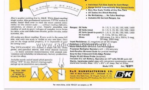
Jeff runs these two side by side on purpose. Two independently-zeroed bridges reading the same node catch a drifting calibration that a single meter can’t flag on its own — if the 311-2 and the 375 agree within their combined tolerance, trust the reading; if they don’t, one of them needs attention before either result is trustworthy. Full sibling dive: B&K Dynamatic 375 VTVM.
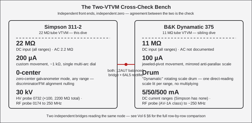
Table 9 — 6. The Two-VTVM Bench: Simpson 311-2 vs B&K Dynamatic 375
| Parameter | Simpson 311-2 | B&K Dynamatic 375 | Detail |
|---|---|---|---|
| Introduced | 311: 1958 · 311-2: 1966 | 1961 | Vol 1 §1 |
| Original price | [NOT FOUND] | $89.95 (1961 ad) | Vol 1 §1 |
| Active devices | 6AL5 (AC rectifier) + 12AU7 (DC bridge) | Same: 6AL5 + 12AU7 | Vol 2 §2-§3 |
| Power-supply rectifier | Silicon diode CR-1 | Selenium rectifier | Vol 2 §5 |
| DC input resistance | 22 MΩ, all ranges | 11 MΩ, all ranges (classic 1 MΩ probe + 10 MΩ divider) | Vol 2 §1 |
| AC input resistance | 2.2 MΩ | [NOT FOUND] for the 375 specifically | Vol 2 §1 |
| Meter movement | Custom D’Arsonval, 200 µA, ~1 kΩ | Jeweled-pivot D’Arsonval, 100 µA — anti-parallax mirrored scale, iridescent knife-edge pointer | Vol 3 §5 |
| Signature feature | 22 MΩ input + zero-center galvanometer mode + 30 kV HV probe | ”Dynamatic” rotating drum scale — one full-size direct-reading scale lit per range, no multiplying | §1 above / this row |
| DC volts ranges | 1.5/5/15/50/150/500/1500 V (7) | Identical cascade: 1.5/5/15/50/150/500/1500 V (7) | §2.1 above |
| AC volts (RMS) ranges | Same 7-range cascade | Same 7-range cascade | §2.2 above |
| AC volts (p-p) ranges | Separate p-p cascade: 4-4000 V p-p (311-2) | Mirrors the RMS cascade (1.5-1500 V p-p) rather than a distinct p-p multiplier set | Vol 2 §3 |
| DC current ranges | None — this is a V/Ω-only VTVM | 5 mA / 50 mA / 500 mA — unusual for a VTVM | §2 above |
| Ohms ranges | 7 decades, ×1-×1M (10 Ω-10 MΩ center) | 7 ranges, 500 Ω-1000 MΩ full scale | §2.5 above |
| Ohms battery | 1.5 V “C”-cell | 1.5 V D-size alkaline cell | Vol 5 §6 |
| Zero-center mode | Yes, any DC range (0.75-0-0.75 V on 1.5 V range) | Not documented — instead a manual DC+/DC− polarity-reversal position on the function switch | §3 above |
| RF probe | 0174 (311-2), 10 kHz-250 MHz | AV-1A-class demodulator probe, “to 250 MHz” (accessory, not standard-issue) | §2.6 above |
| HV probe | 0732, 0-30 kV safe (marked to 50 kV), ×100, raises input to 2,200 MΩ | [NOT FOUND] — no HV probe documented in the 375’s sources | §2.4 above |
| Accuracy | ±3 % DC / ±5 % AC / ±3° ohms | ±1 % multiplier resistors; overall %-of-FS figures [UNCERTAIN] — obscured in the source ad | §1 above |
| Case size | 7½ × 5⅝ × 4½ in | 10½ × 6½ × 4 in | Vol 3 §1 |
| Weight | 4½ lb net | ~8 lb net | Vol 3 §1 |
| Bridge type | Balanced bridge, both triode halves of one 12AU7 | Same topology, same tube role | Vol 2 §2 |
Note — Both instruments are built around the exact same active-device pairing — a 12AU7 balanced-bridge DC amplifier and a 6AL5 peak rectifier — which is why they make sense as a cross-check pair rather than two unrelated designs: a systematic bridge-topology error would show up on both meters, while a component-drift error on just one would show up as disagreement between them. Where they differ is exactly where the redundancy pays off: the Simpson’s doubled 22 MΩ input loads a high-Z node less than the B&K’s 11 MΩ, while the B&K’s rotating-drum scale and added DC current ranges cover things the Simpson doesn’t touch at all.
6.7.1 Which one to reach for
Table 10 — 6.1 Which one to reach for
| Situation | Reach for | Why |
|---|---|---|
| Highest-Z node in a tube circuit (grid bias, AVC line) | Simpson 311-2 | 22 MΩ loads the node half as much as the B&K’s 11 MΩ |
| Need a DC current reading | B&K 375 | Only the 375 has DC mA ranges — the Simpson is V/Ω only |
| FM discriminator / balance-point alignment | Simpson 311-2 | Zero-center galvanometer mode is built in; not documented on the 375 |
| Voltage above 1500 V DC, up to 30 kV | Simpson 311-2 with the HV probe (0732) | The 375 has no documented HV probe |
| Cross-checking a suspect reading | Both, agreement required | The entire point of the two-VTVM bench — see the callout above |
| Reading a single range fast, minimal squinting at a crowded dial | B&K 375 | The Dynamatic drum shows one full-size scale, no multiplying |
6.8 Where the Simpson 260 Fits (for contrast, not comparison)
The Simpson 260 is not a third VTVM on this bench — it’s the loadable 20,000 Ω/V VOM both tube voltmeters exist to out-class on high-Z nodes. On its 1.5 V DC range the 260’s input resistance is only ~30 kΩ (20 kΩ/V × 1.5 V); even on its 500 V range that’s only 10 MΩ — still below the 311-2’s 22 MΩ on every range, and the 260’s resistance changes range-to-range where the VTVM’s does not. That’s the whole reason a VTVM exists: a passive VOM draws current from the circuit under test to deflect its coil, and on a high-impedance tube grid or bias node that current draw itself changes the voltage you’re trying to read. The 260 stays the right tool for continuity, low-Z circuits, and anywhere its loading doesn’t matter — it just isn’t a stand-in for either VTVM on the nodes this bench pair exists to measure.
6.9 Quick Diagnosis: Symptom → Likely Cause
A fast lookup table for the bench, drawn from the refurb material in Vol 5. Work top to bottom — the first two rows are the most common failures on a unit that’s sat in storage.
Table 11 — 8. Quick Diagnosis: Symptom → Likely Cause
| Symptom | Likely cause | Fix / next step | Detail |
|---|---|---|---|
| OHMS ADJUST can’t reach full-scale deflection with leads shorted | 1.5 V “C”-cell exhausted | Replace the battery (B1) | §3 step 6, Vol 5 §6 |
| Erratic meter, dead ohms function, corrosion visible near the battery clamp | Leaked “C” cell corroded the holder/PCB traces | Clean or replace the battery holder; observe polarity on reinstall | §4 step 1, Vol 5 §6 |
| Zero won’t hold, drifts noticeably after warm-up | Weak or mismatched 12AU7 bridge halves | Replace the 12AU7; age it ≥48 h powered before recalibrating; re-zero R29 | §4 step 2, Vol 5 §4 |
| Noticeable zero jump when switching AC↔DC | AC contact-potential pot (R32) out of adjustment | Access via the hole in the case side under the handle; adjust R32 | Vol 5 §2 |
| DC readings drift high over years of use | Precision divider resistors (22 MΩ/20 MΩ network: R17, R34-R37, etc.) drifted high with age | Measure against schematic values; replace out-of-tolerance ±1 % parts | §4 step 3, Vol 5 §5 |
| AC readings normal, RF probe reads dead or erratic | RF probe’s own 6AL5 filament not powered, or probe not fully seated | Reseat the probe in the dedicated RF PROBE jack — full insertion both feeds filament power and auto-disables the internal AC rectifier | Vol 4 §5 |
| Pointer doesn’t sit exactly on zero with power off | Mechanical zero out of adjustment (not electrical) | Adjust the slotted screw under the scale, power off | §3 step 2, Vol 4 §2 |
| Ohms scale seems to read “backwards” (high value near the left) | Not a fault — the ohms arc is a reverse, right-hand-zero scale by design | None needed; this is normal VTVM ohms convention | §2.5, Vol 2 §4 |
| Meter reads full-scale or pinned immediately on OHMS with leads open | Normal — open-circuit resistance reads infinite/full deflection on this arc’s convention; verify with leads shorted instead | Confirm OHMS ADJUST behavior with leads shorted per §3 step 6 | §3 step 6 |
| Reading disagrees with the B&K 375 on the same node | One of the two bridges needs re-zero or re-cal — that’s the redundancy doing its job | Re-warm-up and re-zero both instruments independently before trusting either; recalibrate whichever is out of tolerance | §6 above |
6.10 Front-Panel Control & Jack Legend
Only four controls and a handful of jacks — the whole reason this instrument is fast to operate once you know the layout. (Panel photos of an original Simpson 311, which shares the 311-2’s panel layout and controls, are in Vol 1 and Vol 3.)
Table 12 — 9. Front-Panel Control & Jack Legend
| Control / jack | Function |
|---|---|
| RANGE switch | 7-position range selector, legend runs “1.5V-Rx1 … 1500V-Rx1M” across the DC/AC/ohms range families |
| Function (Circuit Selector) switch | OFF · −DC · +DC · AC · OHMS. OFF also kills power to the tubes. −DC/+DC reverse the meter for polarity without swapping leads. |
| ZERO ADJUST | Front-panel knob; balances the 12AU7 bridge with probe and ground shorted. Reset on every range or function change. |
| OHMS ADJUST | Front-panel knob; sets full-scale (“0 Ω”) deflection on the ohms function. Doubles as the battery-health test — see §3 step 6. |
| GROUND jack | Banana-plug jack for the ground lead (insulated alligator clip at the far end) |
| INPUT / AC-DC-OHMS jack | Accepts the standard probe; probe has its own slide switch (AC/OHMS = direct, DC = series isolating resistor switched in) |
| RF PROBE jack | Dedicated phone jack for the accessory RF/HF probe (0731 on the 311, 0174 on the 311-2); carries signal and filament power to the probe’s internal 6AL5; auto-disables the internal AC rectifier when a probe is inserted |
| Pilot lamp (L1) | “Cloudy-clear” lamp mounted between the GROUND and INPUT jacks — power-on indicator |
| Mechanical zero screw | Slotted screw under the scale glass — power-off pointer adjustment only, not part of normal operation |
Glossary
Table 13 — 10. Glossary
| Term | Meaning |
|---|---|
| VTVM | Vacuum Tube Voltmeter — a voltmeter that uses a tube (here, the 12AU7) as a high-impedance buffer/amplifier ahead of the meter movement, so the meter loads the circuit under test far less than a passive VOM |
| Balanced bridge | The 12AU7’s two triode halves form two arms of a DC bridge; the meter reads the imbalance between them. Drifts common to both halves (heater voltage, warm-up, aging) cancel — the source of the design’s stability |
| D’Arsonval movement | The classic moving-coil meter mechanism — a coil in a fixed magnetic field, deflection proportional to current through the coil |
| RMS | Root Mean Square — the AC voltage figure that equates to an equivalent heating DC voltage; valid only for sine waves on this instrument’s black arcs |
| p-p (peak-to-peak) | The full swing of an AC waveform from most-negative to most-positive point; valid for any waveform shape, read on the red arcs |
| CR-1 | The power-supply’s silicon rectifier diode (750 mA) — converts the transformer’s AC to the DC that powers the tubes’ B+ and heaters. Not a measuring element. |
| ”C” cell | Standard 1.5 V dry-cell battery size (larger than AA, smaller than D) — powers the ohms function only |
| Ω/V (ohms-per-volt) | The sensitivity figure for a passive VOM like the Simpson 260 (20,000 Ω/V) — input resistance = sensitivity × range voltage. A VTVM’s input resistance instead stays fixed (22 MΩ here) regardless of range, which is the whole point of the design. See §7 above. |
| Zero-center (galvanometer) mode | Using a DC range with the pointer resting at mid-scale rather than left-edge, so the meter can swing either side of zero — useful for balance/null work such as discriminator alignment |
| Contact potential | A small, tube-inherent DC offset at the grid that shifts the bridge’s zero point when switching between AC and DC functions; compensated internally by R-32 |
Sources
- Simpson Electric Co., Operator’s Manual — Vacuum Tube Voltmeter Model 311-2, © 1966 (part 5-110700). https://www.simpson260.com/downloads/simpson_311-2_user_manual.pdf
- Simpson Electric Co., Operator’s Manual — Vacuum Tube Voltmeter Model 311, © 1958 (printing 1-62-JM-BL-Rev.1). https://simpson260.com/downloads/simpson_311-1_user_manual.pdf
- Simpson 311-2 manual mirror: https://archive.org/details/Simpson_311-2_VTVM
- Manual index (BAMA): https://bama.edebris.com/manuals/simpson/311-2
- Nuts & Volts, “Vintage Tek: The Vacuum Tube Voltmeter” — https://www.nutsvolts.com/magazine/article/vintage-tek-the-vacuum-tube-voltmeter
- Radiomuseum — Simpson VTVM family (312, 303) — https://www.radiomuseum.org/r/simpson_vacuum_tube_volt_ohmmete.html ; https://www.radiomuseum.org/r/simpson_vacuum_tube_voltmeter_303.html
- Simpson 313 Solid-State (FET) VOM — ManualsLib product page: https://www.manualslib.com/products/Simpson-313-Solid-State-Vom-14060996.html
- radiomuseum.org — B&K Dynamatic 375 (year, tubes, selenium B+, price, size, schematic): https://www.radiomuseum.org/r/dynascan_k_dynamatic_375.html
- radiomuseum.org — B&K 375 1961 advertisement spec block (ranges, 11 MΩ, 100 µA movement, 1½ V battery, ±1 % multipliers, size/price): https://www.radiomuseum.org/images/radio/b_k_dynascan_corp/b_k_dynamatic_375_2105857.jpg
- BAMA manual archive — B&K 375: http://bama.edebris.com/manuals/b&k/375
- Antique Radio Forums — “B&K Dynamatic 375 VTVM woes” (grounding fix, cal pots, 12AU7 + 6AL5): https://antiqueradios.com/forums/viewtopic.php?p=1517272
- Surplus Sales of Nebraska — B&K RF Demodulator Probe (AV-1A, “to 250 MHz, for most VTVMs”): https://www.surplussales.com/items/99536/bk-rf-demodulator-probe/