Supreme Instruments 385 Automatic Tester · Volume 1
Supreme 385 Automatic — Vol 1: Overview — What This Tube Tester Is & the Emission-vs-Gm Question
A 1935 Depression-era combination instrument that stages, in its own instruction manual, the exact emission-versus-transconductance argument this two-tester bench is built to settle.
1.1 Why this instrument is kept next to a much newer one
Two tube testers sit on the bench: this one, a Supreme “385 Automatic” built in Greenwood, Mississippi in 1935, and a Heathkit TT-1 built roughly a quarter-century later, around 1959. They are not redundant. They test tubes by two fundamentally different methods, and each catches failures the other one misses. That contrast — not nostalgia — is why both stay in service.
- The 385 is an emission tester. It runs the tube as a diode-connected emitter under approximately its rated load and reads the resulting DC current on a GOOD/?/BAD scale. It asks one question: does the cathode still emit enough electrons at all?
- The TT-1 (covered in its own volume series — see the sibling dive) is a dynamic mutual-conductance (Gm) tester. It biases the tube at a realistic operating point, injects a small AC signal on the grid, and reads the resulting AC plate-current swing directly in micromhos (µmhos) — the actual figure of merit for gain. It asks a sharper question: how much does this tube still amplify?
A tube can pass the first test and fail the second. A cathode with plenty of raw emission capacity can have lost enough transconductance — through age, gas, or a shifted operating point — that it barely amplifies, and an emission tester has no way to see that, because it never puts a signal through the tube at all. Figure 1 lays the two methods side by side.
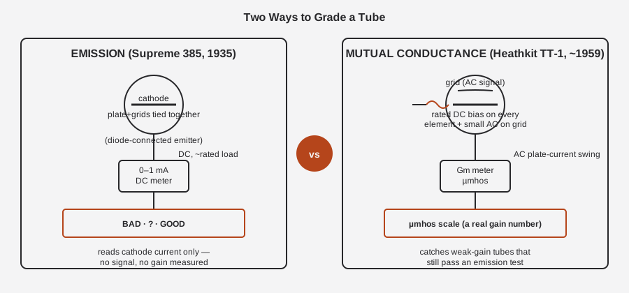
What makes the 385 worth reading closely, rather than dismissing as “the crude one,” is that its own factory manual makes this exact argument — in 1935, before the Heathkit even existed as a company. Two full pages of the instruction booklet (“The New Supreme Model ‘385 Automatic’ Tester”) are devoted to explaining why Supreme chose emission over mutual-conductance, not because the engineers didn’t understand Gm testing, but because they’d priced it out and decided against it. That argument is the spine of this whole volume series, and it deserves to be quoted directly rather than paraphrased, because it is a period engineer’s own cost/accuracy tradeoff, not a modern collector’s retrospective judgment.
From the manual, on why a true grid-shift (Gm) tester was rejected: a proper mutual-conductance test “would require batteries or a DC power pack … a control for each tube element … about ten controls [for a 7-element tube] … would cost several hundred dollars, and require about an hour to test a set of tubes.” Their conclusion: “the emission tester came into favor, because a well-designed emission tester is more accurate than a poorly-designed grid-shift tester … about all that can happen … is the depreciation of the emitting qualities of the cathode … so why not test a tube by measuring the emission current?”
Supreme even quantified the tradeoff they were making: an emission design, done well, gives “accuracy in the order of 90%” at a fraction of the cost, against “95% or more” for an expensive Gm set. That is a remarkably candid number to print in a sales manual — a manufacturer admitting its flagship instrument is, by its own estimate, roughly 5 percentage points less accurate than the gold-standard alternative it chose not to build. Vol 6 of this series returns to this comparison in numeric form, once the TT-1’s own numbers are on the table; for now, the point is that the emission-versus-Gm debate is not something later collectors imposed on this tester — Supreme’s own engineers staged it, on paper, in 1935, and picked a side for commercial reasons.
In practice, “misses” and “catches” translate to a concrete bench scenario. A tube pulled from a radio that’s gone weak, distorted, or motorboating is a classic candidate for both testers. Run it on the 385: if the cathode has genuinely lost emission capacity — the classic old-tube failure mode, where years of heater cycling and ion bombardment slowly deplete the oxide coating — the Quality Test current will sag below the load-line threshold Supreme calibrated into that tube type’s Tube List entry, and the meter needle will sit in the BAD arc. That is exactly the failure this instrument was built to catch, and it does it in seconds with no signal generator, no bias supply beyond what’s already built in, and no interpretation skill beyond reading GOOD/?/BAD off a labeled arc. But if the same tube’s cathode still passes plenty of current under DC load — enough to read GOOD or borderline-”?” — while its transconductance has separately degraded (a shifted grid-to-cathode spacing from thermal cycling, a subtly gassy envelope, drifted bias characteristics that put the tube’s actual operating point off the design curve), the 385 has no way to see it, because nothing in the Quality Test circuit ever asks the tube to amplify anything. The tube reads GOOD on the 385 and goes back into the radio, which keeps sounding weak. That is precisely the gap the TT-1’s Gm test is built to close, by putting a small AC signal through the tube at a realistic bias and measuring what comes out the other side. Neither failure mode is rare on Depression- and postwar-era tubes with decades of service hours on them, which is the practical reason — beyond the historical interest — that Jeff keeps both testers rather than treating one as a strict upgrade over the other.
One more piece of period technology is worth flagging here because it recurs through the rest of this dive: the 385’s power supply rectifies with a copper-oxide instrument rectifier (for the AC-voltmeter path) plus a rectifier tube in a self-contained power pack (for the DC ohms and capacitor-test ranges) — not a selenium rectifier. That is exactly correct for 1935; selenium rectifiers did not become common in US consumer and instrument gear until the late 1930s and 1940s, so a 385 built with copper-oxide and a thermionic rectifier tube is using the mainstream technology of its actual introduction year. Vol 2 covers how that copper-oxide rectifier’s non-linear “current-density” behavior shaped the AC-voltmeter circuit design, and Vol 5 covers what aging does to it and how to evaluate one on a unit that’s sat unused for decades.
1.2 What this specific unit is
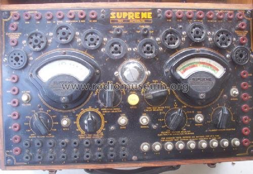
Set the “Automatic” name aside for a moment (it gets its own section below, because it is routinely misread) and look at what the 385 actually does. It is not, strictly, a tube tester with extra features bolted on. The factory manual itself avoids the term “tube tester” and calls it a “multi-purpose tester” and “analyzer.” Under one wood case with a bakelite panel and two matching 5-inch fan-shaped meters, Supreme built four separate instruments that share a chassis, a power supply, and a metering system:
- An emission tube tester — the “Quality Test,” GOOD/?/BAD verdict, described above.
- A set analyzer — the “Free Reference Point System of Analysis,” which lets a serviceman test a tube in the customer’s radio, in circuit, via an analyzing cable that plugs into the set’s tube socket, plus a self-contained “grid-shift” battery for point tests on the tube while it’s still seated in the chassis.
- A volt-ohm-milliammeter (VOM) — DC volts, AC volts, DC milliamps, and resistance, all built on the same two meter movements via range-multiplying networks.
- A capacitor tester — electrostatic leakage read by a neon indicator, electrolytic condition read as GOOD/BAD on the meter.
Figure 2 maps those four functions back onto the one case. Vol 2 works through the circuit that makes each function share the same pair of 0–1 mA / 300 Ω meter movements — “uni-construction,” in Supreme’s own phrase, doing the work of roughly thirty-two single-range meters with two.
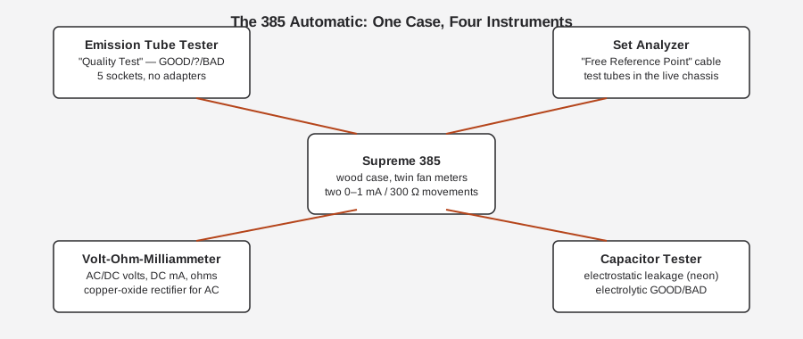
Two 5-inch fan-shaped d’Arsonval meters are the instrument’s signature look and Supreme’s house style of the period — the company’s design ethos, per a later EDN retrospective on Supreme, was that test gear should be “functional and beautiful,” with etched panels and fan-shaped movements distinguishing Supreme’s products on a service bench full of round-dial competitors. The left meter carries the VOM/analyzer scales (a multi-scale ohms arc plus volts/milliamps/mfd markings); the right meter carries the verdict scales — a GOOD CAPACITOR / BAD CAPACITOR arc above a BAD TUBE / ? / GOOD TUBE arc, both English-reading, over a 0–100 scale. Nowhere on that face is there a µmhos scale, because the 385 never generates a µmhos number — Vol 3 covers the meter faces and Vol 4 walks through reading a verdict in practice.
What makes the sharing of two meters across four instruments possible, and what Supreme’s copy calls “uni-construction,” is a network of switched multipliers and shunts feeding a single common 0–1 mA / 300 Ω movement per meter. Rather than building a dedicated movement for each function — one for volts, one for ohms, one for the tube-quality scale, one for capacitor leakage — Supreme designed one sensitive movement and surrounded it with enough switched resistance/reactance networks that it could be pressed into service as roughly thirty-two different single-range meters depending on which selector is set where. That is not a cosmetic simplification; it is the entire reason a 1935 combination instrument at this price point could exist at all. A dedicated movement for every range on every function would have meant dozens of meters in the case, which neither the cost nor the panel space allowed. Vol 2 traces exactly how each function’s switching network reconfigures the shared movements, and Vol 3 catalogs the full set of scales printed on each meter face.
Each of the four sub-instruments deserves a beat of its own before moving on, because “combination tester” undersells how much is actually packed into the case:
- The emission tube tester is the function most people mean when they say “tube tester,” and it is covered in depth starting in Vol 2. In brief: the tube under test is wired as a diode-connected emitter, run under approximately its rated load, and the resulting DC current is read on the GOOD/?/BAD scale after the operator dials in that tube type’s settings from the printed Tube List card.
- The set analyzer turns the 385 into a service tool that works without pulling the tube at all. Supreme’s “Free Reference Point System of Analysis” uses a cable that plugs into the radio’s own tube socket (via an adapter plug inserted where the tube normally sits, or through a breakout at the socket), letting a serviceman probe voltages and currents at known reference points in a live, working chassis. A separate self-contained “grid-shift” battery supports point tests on a tube while it remains seated in the set. This is a genuinely different workflow from bench-testing a pulled tube, and it is the feature that justifies calling the 385 an “analyzer” rather than just a tester.
- The VOM section turns the same shared meters into a general-purpose volt-ohm-milliammeter: DC volts from 0 to 1250 V across six ranges, AC volts over the same six-range span via the copper-oxide rectifier, DC milliamps from 0 to 1250 mA across six ranges, and resistance from a quarter-ohm up to 20 MΩ across six ranges, the low ranges powered by a self-contained flashlight battery and the two highest (0–2 MΩ, 0–20 MΩ) by the internal power-pack.
- The capacitor tester checks both failure modes that matter for a service-bench capacitor check: electrostatic leakage (paper/mica caps), read by the same neon-glow principle used for tube leakage, and electrolytic condition, read as a GOOD/BAD verdict on the meter rather than a numeric capacitance figure for that failure mode. Straight capacitance is also measurable, 0.001 to 12.5 mfd across six ranges, using transformer taps as the reference.
1.3 “Automatic” is a marketing name, not a mechanism
This is the single most important correction to carry through the rest of this dive, because it is easy to get wrong by pattern-matching to later tube testers. Several Supreme models from the late-1930s 500-series really did use roll charts, and other manufacturers’ testers of the same general era used rotating drums or bank-switch selectors to speed up tube setup. It would be reasonable to assume “385 Automatic” describes one of those mechanisms. It does not.
There is no rotating drum in the 385. There is no roll chart. There is no single knob that dials in a tube type. Setting up a tube on this instrument is a manual, multi-step process:
- Look the tube up on the printed “TUBE LIST” card that ships with every tester — a settings chart, not a chart reader mechanism.
- Set the Filament Voltage Selector to the value given for that tube type, off a many-tapped filament transformer secondary.
- Set the Filament Return Selector, which routes the heater/filament return to whichever socket pin that tube’s heater actually uses — the trick that lets one physical socket serve tubes with different pinouts.
- Set the Quality Test Selector, the variable resistor that establishes the correct emission load for that tube type.
- Insert the tube into the correct one of five sockets — 4-, 5-, 6-, 7-, or 8-pin — and read the meter.
Supreme’s own copy calls this a “Simple 3-step A.C. tube Tester” — three knob settings, not one, and certainly not zero. So what does “Automatic” actually refer to? Three specific, real features, all named explicitly in the manual’s own “385 Quick-Facts”:
Table 1 — real features, all named explicitly in the manual's own "385 Quick-Facts"
| What “Automatic” means on the 385 | How it works |
|---|---|
| Universal, no-adapter socket | The 8-contact octal socket has its pins arranged on a 45° circle; the new metal (octal-family) tubes use pin spacing at multiples of 45°, so lower-pin-count members of that metal-tube family (5-/6-/7-pin metal types) drop straight into the same octal socket with the extra contacts left blank — one of the five sockets, not a replacement for the other four. No adapter plugs, no risk of a tube going in the wrong socket. |
| Automatic (no-pushbutton) current metering | ”Circuit-breaking twin jacks” in the analyzer section keep the measuring circuit closed until two pin plugs are inserted, whereupon inserting the plugs breaks the circuit and inserts the meter in series — this eliminates a separate pushbutton switch for each range and gives what Supreme calls “automatic current measurements.” |
| Automatic leakage indication | The neon-lamp leakage test (Vol 2 §4) glows by itself on whichever pair of tube elements is actually leaking — the operator doesn’t select which pins to test; the neon indicates the fault automatically. |
None of those three features is a tube-selection mechanism. Treat any description of the 385 as having “single-knob automatic tube selection” or a “rotary drum” as a misreading of the name — the factory manual is unambiguous on this point, and it is worth being blunt about because the mistake is an easy one to repeat from secondhand summaries.
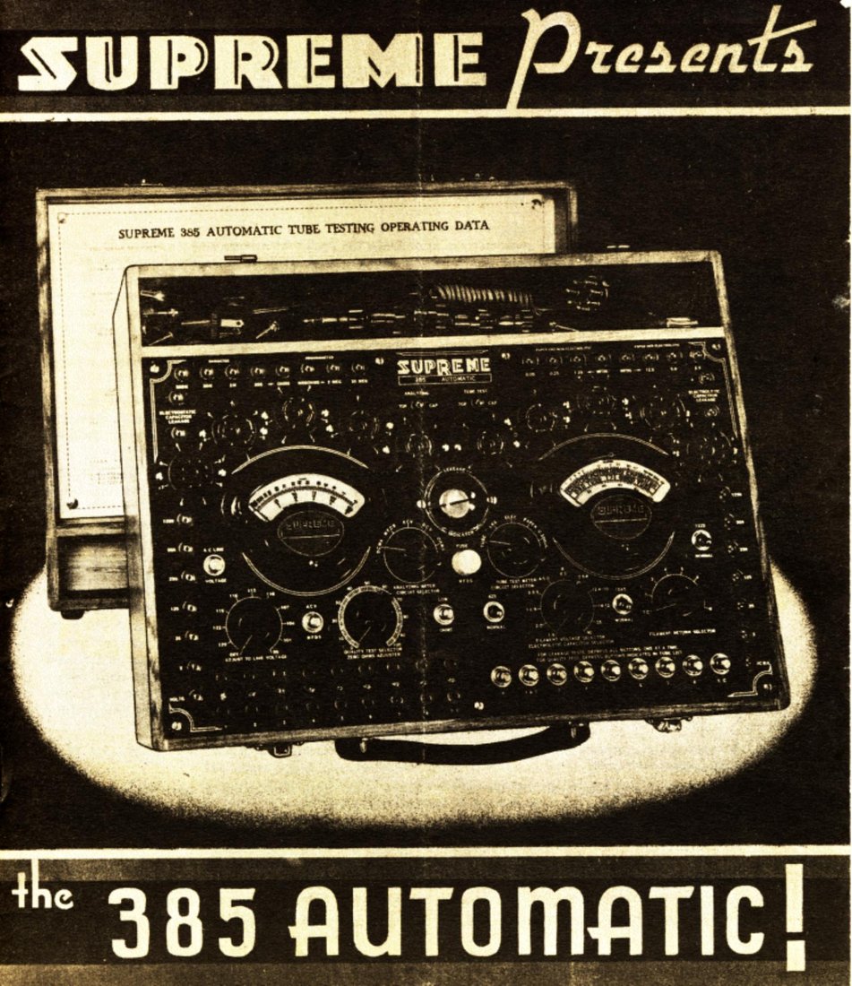
⚠ Note — The manual cover itself (Figure 3, below) shows the unit as delivered: the front panel in its wood case with the printed Tube Testing Operating Data card visible in the lid. That card is the “TUBE LIST” — read it as the period equivalent of a lookup table, not a chart-reader mechanism.
1.4 Maker and era
Supreme Instruments Corporation was founded in 1926 in Greenwood, Mississippi, by Jewell R. Williams, starting in a small garage. Williams left around 1930 to found a separate company (Apparatus Design Co., Little Rock); B. F. Dulweber took over Supreme, assisted by his son D. N. Dulweber, and by around 1930 the company had narrowed its focus to test equipment for radio servicemen exclusively. That focus produced the 385 five years later.
The 385 was introduced in 1935 — Radio Craft’s May 1935 back cover carried the ad “Presenting the Supreme 385 Automatic,” and the manual’s own emphasis on the then brand-new 8-pin metal tubes (“probably the first tester to be announced for complete tests of all 8-pin tubes”) lines up with RCA’s 1935 announcement of the metal-tube line. The tester stayed in the field for years afterward — Supreme published an updated Tube List for it as late as 1939, and a period sales listing pairs a 385 with a 1939-dated manual — so treat it as a mid-1930s instrument (1935 introduction) sold and supported through the late 1930s, rather than a single snapshot year.
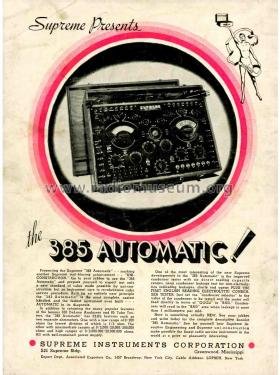
It sold at a dealer-net wholesale price of $77.95, “for 98–125 volt, 60-cycle” mains, with “special voltage or frequency instruments” available at extra cost — a reminder that 1935 US mains supply was not yet the tightly standardized 117 V/60 Hz of later decades. In a wood carrying case with a bakelite front panel, the unit runs roughly 18 inches wide and about 22 lb — secondary sources disagree on the exact case depth, so treat only the width and weight as solid.
Supreme went on to build military tube testers and VOMs through World War II out of a second Greenwood factory (reportedly over 1,500 panel meters a day at peak), moved into TV service gear after the war, and was acquired by Hickok Electrical Instruments in 1956, becoming Hickok-Supreme. The 385 sits early in that arc — one of Supreme’s more ambitious mid-1930s combination analyzers, sharing tube data with the contemporary Model 89/89-D bench tester, and predating the roll-chart mechanism Supreme would introduce on the late-1930s 500-series testers. That roll chart is real Supreme engineering — it’s just a different, later product, not this one.
1.4.1 Where the 385 sat in the mid-1930s service-bench market
Supreme was one of several serious American radio-service test-equipment houses competing for the same customer — the independent radio repairman — through the late 1920s into the 1950s: Weston, Jewell (later folded into Hickok), Triplett, Readrite, and Sylvania/Precision all sold overlapping lines of tube testers, set analyzers, and VOMs to the same trade during the same years. Supreme’s particular reputation was built on analyzers and tube testers specifically, and the 385 shows why: at $77.95, it undercut buying four separate single-purpose instruments (a tube tester, a set analyzer, a VOM, and a capacitor tester individually) while still using premium-looking fan-shaped meters rather than the plainer round dials common on cheaper competing testers. For a Depression- era independent serviceman, that combination — one case, one price, four functions, and enough metering precision that Supreme could credibly claim “accuracy in the order of 90%” on the tube grade — was the actual value proposition, not any single headline feature.
It is worth being explicit that the “Automatic” name itself was doing real marketing work in that competitive field. A 1935 radio serviceman shopping test equipment would have seen “automatic” and reasonably associated it with speed and reduced operator error — which the socket geometry and circuit-breaking jacks genuinely deliver — without it promising (or delivering) push-button tube selection. Reading the name as a speed/reliability claim about setup mechanics that already exist (no wrong socket, no wrong pushbutton, automatic leakage flagging) rather than a claim about replacing the Tube List lookup keeps the marketing honest on Supreme’s own terms.
1.5 Headline facts
Table 2 — Headline facts
| Item | Value | Confidence |
|---|---|---|
| Full name | Supreme Model “385 Automatic” | confirmed — manual title page |
| Type | Combination emission tube tester + set analyzer + VOM + capacitor tester | confirmed |
| Tube-test method | Emission (“Quality Test”), DC current under ~rated load, GOOD/?/BAD | confirmed — factory manual |
| Introduced | 1935 (Radio Craft, May 1935 ad) | confirmed, one source says 1936 |
| In-field support | Tube-data updates through 1939 | confirmed |
| Price | $77.95 dealer-net wholesale, 98–125 V / 60 Hz mains | confirmed — manual back page |
| Maker | Supreme Instruments Corp., Greenwood, Mississippi | confirmed |
| Company span | Founded 1926; acquired by Hickok 1956 | confirmed |
| Meters | Two 5-inch fan-shaped d’Arsonval, 0–1 mA / 300 Ω each | confirmed |
| Sockets | Five, no adapters: 4-, 5-, 6-, 7-, 8-pin (octal/metal) | confirmed |
| Rectifiers | Copper-oxide (AC volts) + rectifier tube in a self-contained power pack (DC ohms/cap) — no selenium | confirmed |
| Case | Wood carrying case, bakelite panel, ~18 in wide, ~22 lb | width/weight confirmed, depth disputed between sources |
| ”Automatic” refers to | No-adapter socket + no-pushbutton metering + automatic leakage indication — not a tube-selection drum/knob | confirmed — factory manual |
1.5.1 Emission vs Gm, in brief
Table 3 — Emission vs Gm, in brief
| Supreme 385 (this unit) | Heathkit TT-1 (sibling) | |
|---|---|---|
| Era | 1935 | ~1959 |
| Method | Emission — DC current, diode-connected tube, ~rated load | Mutual conductance (Gm) — biased tube, AC signal on grid |
| Reads | GOOD / ? / BAD (English scale) | Transconductance directly, in µmhos |
| Catches | Cathode that no longer emits adequately | Cathode that emits fine but no longer amplifies |
| Misses | A tube with collapsed gain that still emits | Nothing structurally, by design — this is the gain measurement |
| Setup speed | Slower, manual — three rotary knobs off a printed Tube List card | Faster once biased — no per-tube variable-resistor lookup on this axis |
| Manual’s own stance | Explicitly chose emission over Gm on cost/complexity grounds | N/A — TT-1 exists specifically to do what the 385 chose not to |
1.6 Depth index — where the rest of this dive goes
- Vol 2 — How It Works: The Test Method & Circuit. The emission (“Quality Test”) circuit in detail — how the tube is wired as a diode-connected emitter, how the Quality Test Selector sets the per-tube load, the 10%-of-circuit-resistance overload-protection design, the neon leakage/short/open test and its deliberately desensitized threshold, and the copper-oxide AC-voltmeter network (including the reactive-multiplier trick on the 5 V range). This is where the manual’s own pp. 8–9 argument against a grid-shift design gets the full technical treatment.
- Vol 3 — Inside This Unit: Hardware, Meter, Sockets & Setup. The chassis, the twin fan meters and their scales, the filament transformer and its tap selectors, the five sockets and the 45°-pin-geometry trick that makes them adapter-free, and the physical layout of the “Automatic” mechanisms described above.
- Vol 4 — Using It: Setting Up & Grading a Tube. A step-by-step walkthrough of the actual 3-step procedure — reading the Tube List card, setting the three knobs, choosing a socket, and interpreting a GOOD/?/BAD verdict — plus the set-analyzer function for testing a tube in a live chassis.
- Vol 5 — Refurbishing & Calibration. Bringing a ~90-year-old mains instrument back up safely (variac, isolation transformer, series-lamp limiting), recapping the electrolytics and the calibration-critical AC-multiplier capacitors, evaluating the copper-oxide rectifier and the power-pack rectifier tube, and the manual’s own 5 V AC-range calibration procedure.
- Vol 6 — Cheatsheet & Emission vs Gm: the Two-Tester Bench. A quick-reference card for this unit, plus the full numeric comparison against the Heathkit TT-1 — what a two-tester bench catches that either tester alone would miss, and how to decide which one to reach for first on an unknown tube.
Sources
- Supreme Instruments, “The New Supreme Model ‘385 Automatic’ Tester” (factory technical manual /
Radio Craft reprint, 13 pp.; front-panel photo, Figs. 1–13 schematics, “385 Quick-Facts” back
cover with meter-scale art and price), via stevenjohnson.com:
https://stevenjohnson.com/supreme/data/supreme385-manual.pdf - Supreme Instruments archive downloads (385 Technical Manual, Instructions & Tube Data Sheet,
“89 series and 385 Tube Data,” “1939 Updated Tube List”):
http://www.supremeinstruments.org/data.htm - Radiomuseum, “Automatic Tube Tester 385, Supreme Instruments” (1935 date, $77.95, Radio Craft
May 1935 ad, photo set):
https://www.radiomuseum.org/r/supreme_in_automatic_tube_tester_385.html - Supreme Instruments Corp. company history:
http://www.supremeinstruments.org/history.htm - EDN, “What’s It Worth: Supreme Instruments — Function Meets Art” (company history, design
ethos, Hickok acquisition):
https://www.edn.com/whats-it-worth-supreme-instruments-function-meets-art/ - WorthPoint listing, “Supreme 385 Automatic Tube Tester with Original Manual – 1939” (confirms
in-field use through 1939):
https://www.worthpoint.com/worthopedia/supreme-385-automatic-219583399 - Steven Johnson, “Supreme Tube Testers and Radio Analyzers” (model summary table — cited for
general context only; its “385 = transconductance” entry contradicts the factory manual and is
not relied on for the test-method claim):
https://stevenjohnson.com/supreme/tubetesters.htm