Supreme Instruments 385 Automatic Tester · Volume 2
Supreme 385 Automatic — Vol 2: How It Works — The Test Method & Circuit
Inside a 1935 emission tester: a diode-connected tube, a per-type variable resistor, and two clever tricks — a phase-shifted AC multiplier and a deliberately blind neon lamp — that let two fan meters do the work of thirty.
2.1 Scope of This Volume {.unnumbered}
Vol 1 established what the Supreme 385 Automatic is — a 1935 combination instrument built around an emission tube test, not a mutual-conductance (Gm) test, despite the “Automatic” name and despite at least one modern collector reference mislabeling it a transconductance tester. This volume opens the box on how that emission test — and the analyzer/VOM/capacitor functions riding alongside it — actually works, at the schematic level, using the factory technical manual’s own figures (Figs. 1–13) as ground truth.
Four circuits are covered in order:
- The Quality Test — the emission test proper: a tube wired as a diode-connected emitter, a per-type variable load resistor set from a printed card, and a meter reading GOOD/?/BAD.
- The neon leakage/short test — a separate, deliberately crude pass/fail check for element-to-element shorts and leakage, using 110 V AC, a blocking capacitor, and a neon glow lamp.
- The copper-oxide AC voltmeter — the analyzer/VOM’s AC-volts path, notable for a reactive (capacitive) multiplier trick on its lowest range that a resistor-only design could not match.
- The rectifier-tube power pack — the self-contained DC supply behind the high-ohms ranges and the capacitor tests.
Hardware placement (where these circuits physically live in the case, which knob is which) is Vol 3’s job. Step-by-step operating procedure is Vol 4’s. This volume is strictly how the electrons move — and, per the pairing theme that runs through this whole dive, why that path can only ever measure emission, never gain.
⚠ Danger — every circuit described below lives inside a 1935, transformer-isolated-but-otherwise-bare chassis with exposed 110 V AC, a ~350 V rectifier-tube winding, and no polarized plug. Nothing in this volume is a green light to probe the chassis live. See
../../../_shared/legal_ethics.mdfor the mains/HV discipline this instrument demands, and Vol 5 for the specific bring-up procedure.
2.2 The Quality Test — Circuit and Method
2.2.1 The core idea: run the tube as a diode and read what comes out
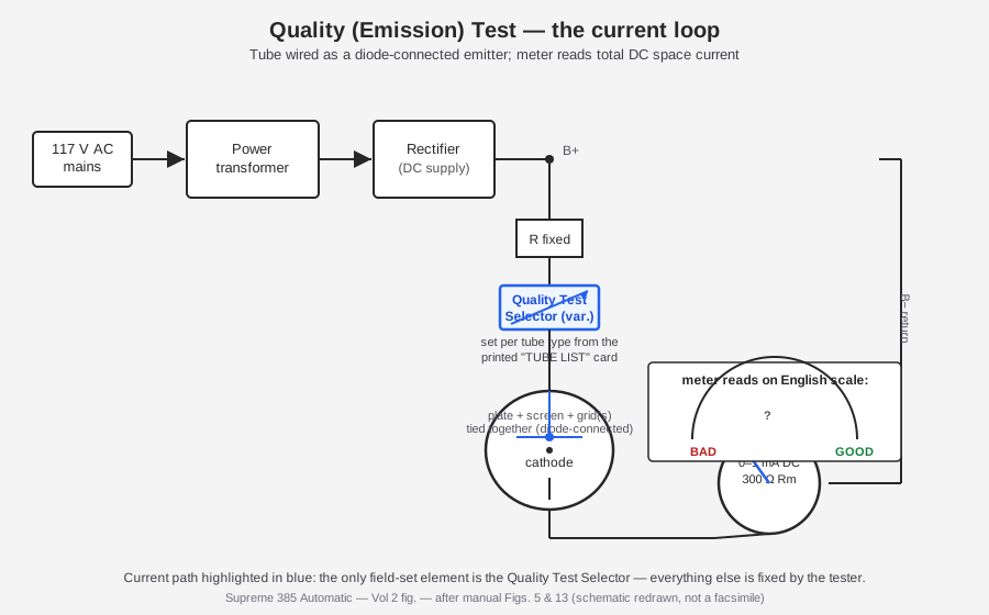
Strip away the knobs and the fan-shaped meter face, and the Quality Test is almost insultingly simple. The factory manual’s own description of Fig. 5 is the cleanest statement of it:
“the direct current passed by the tube is measured by one of the meters … the current is limited by the tube and two resistors, one of which is variable. The value of the variable resistor is predetermined for each type of tube, and the corresponding control-knob setting is included in a ‘TUBE LIST’ card which accompanies each tester.”
Unpacked, that’s three moves:
- Tie every control element of the tube to the plate. Grid, screen grid, suppressor — whatever the tube type has — all get strapped together with the plate, so the tube behaves as a two-terminal device: cathode on one side, everything-else-as-plate on the other. This is what “diode-connected” means here. There is no AC test signal and no attempt to bias the grid at a realistic operating point; the tube is simply asked “how much total current will you pass under load,” full stop.
- Feed that two-terminal device from a DC supply through a load network. The load is two resistors in series — a fixed one and a variable one — between the DC source and the tied-together plate structure.
- Read the resulting current on the meter, calibrated not in amps or volts but directly as a verdict: GOOD / ? / BAD on an English-reading arc.
Figure 2, “Vol 2 fig. — the Quality-Test loop,” below, redraws that path.
2.2.2 “Approximately rated load” — what the load resistor is really doing
The manual’s Quick-Facts sheet is explicit that the goal is realism in one dimension only: “Tests all tubes at approximately RATED LOAD for utmost accuracy.” That single phrase is the whole design philosophy of an emission tester. A tube’s data sheet specifies a plate voltage and plate current at which the tube is meant to operate; the Quality Test tries to reproduce roughly that operating current, not the operating conditions — there is no attempt to reproduce the correct grid bias, the correct screen voltage relative to plate, or any AC signal swing. The variable resistor is the knob that does this reproduction: set it too low and every tube reads high (false GOOD); set it too high and every tube reads low (false BAD). Getting it right, tube type by tube type, is the entire job of the printed Tube List card — the tester itself carries no intelligence about what a 6J5 or an 80 or a brand-new 6L6 metal tube is “supposed” to draw. That intelligence lives entirely on paper, updated as new tube types appear (the surviving 1939 revision is the last known update to the card; see Vol 5).
This is the single biggest thing to internalize about “Automatic” in this instrument’s name: nothing about the Quality Test itself is automatic. The variable resistor is a manually turned dial, set from a manually read chart, before every single tube. What is automatic is downstream of this — the socket that accepts the tube without an adapter, and the current metering that needs no pushbutton (Vol 1 §“The ‘Automatic’ Question”; Vol 3 covers the physical knob layout; Vol 4 walks the actual look-up-and-set sequence).
2.2.3 The meter face: GOOD / ? / BAD, not micromhos
Both of the 385’s meters are the same basic part — a 5-inch fan-shaped d’Arsonval movement, 0–1 mA DC, 300 Ω internal resistance (the manual’s Fig. 11 labels it plainly: “300 OHMS – Rm, 0–1 M.A. D.C. METER”). Multi-range operation on both the volts/ohms/mA analyzer functions and the tube/capacitor verdict functions is achieved entirely through switched multiplier and shunt networks in front of these two identical movements — the manual’s own boast is that this “uni-construction” scheme lets two meters do the work of roughly thirty-two single-range meters.
Table 1 — The meter face: GOOD / ? / BAD, not micromhos
| Meter | Scale arcs present | What it reads |
|---|---|---|
| Left meter | multi-range OHMS arc + a combined VOLTS – MILLIAMPERES – MFDS arc | analyzer/VOM functions: DC/AC volts, DC mA, resistance, and capacitance value |
| Right meter | upper arc GOOD CAPACITOR … BAD CAPACITOR; lower arc BAD TUBE … ? … GOOD TUBE over a 0–100 span | the tube Quality Test verdict, and the electrolytic-capacitor GOOD/BAD verdict |
The right-meter tube arc is the one that matters for this section. It is explicitly English-reading — the manual’s language, not a modern gloss — meaning the needle position is calibrated so an untrained radio serviceman reads a plain-language verdict, not a number he then has to interpret against a data sheet. That is the entire commercial argument for an emission tester over a Gm tester: cheap enough, and simple enough, that a counter clerk can grade a tube in seconds. No image of the meter-scale artwork itself survived into this dive’s verified image set; the arcs above are transcribed directly from the manual’s Quick-Facts page description and are reproduced schematically in Fig. 2 above rather than photographed.
2.2.4 The protection trick: why a shorted tube can’t hurt the meter
A tube tester’s own-socket circuit gets shorted tubes shoved into it constantly — that is, after all, one of the two failure modes (open cathode / shorted elements) the whole instrument exists to catch. The 385’s answer is a deliberately conservative ratio between the external circuit resistance (the fixed resistor plus the Quality Test Selector) and the total circuit resistance (external plus a normal tube’s own internal resistance at the test point):
“the external circuit resistance, when the Quality-Test selector is properly set, is 10% of total circuit resistance including a normal tube”
Do the arithmetic on that ratio and the protection scheme falls out immediately:
Table 2 — Do the arithmetic on that ratio and the protection scheme falls out immediately
| Condition | Effective circuit resistance | Current relative to a normal reading |
|---|---|---|
| Normal tube, selector correctly set | R(external) + R(tube, normal) = R(external) ÷ 0.10 | 1× (baseline, whatever the Tube List calls for) |
| Tube shorted (R(tube) → 0) | R(external) alone | up to 10× |
| Tube open (R(tube) → ∞) | effectively infinite | → 0 (reads BAD, safely) |
Because the external resistors are fixed at roughly one-tenth of the total normal-operating resistance, the worst case a dead short can do to the meter is impose a ten-times overload — not a hundred-times, not an unlimited short-circuit surge. A 0–1 mA movement seeing a 10 mA transient is unpleasant but survivable, and the manual states plainly that with this ratio in place “both meters [are] fully protected.” This is a deceptively elegant piece of 1930s design: rather than adding a separate protection relay or fuse in the tube-test loop, Supreme built the safety margin directly into the same resistor network that sets the test load, so protection costs nothing extra and can never be defeated by a wrong knob setting — the manual specifically claims “the tester cannot be harmed by an incorrect selector setting or by a ‘shorted’ tube.”
⚠ Danger — this protection scheme is about the meter, not the operator. It says nothing about the DC supply feeding the loop, which on a 1935 chassis is not isolated the way a modern bench supply is. Treat the Quality Test circuit with the same mains-safety discipline as everything else on this chassis (see the callout above and Vol 5).
Fig. 13 shows a second, independent layer of margin behind the resistor-ratio trick above: a meter shunt network of roughly 4,220 Ω, equivalent to extending the movement’s usable range to something on the order of 0–1,000 µA-equivalent rather than exposing the bare 0–1 mA / 300 Ω movement directly to the Quality-Test loop. Between the two protections — the 10%-of-total resistor ratio limiting the maximum current a short can ever produce, and the shunt network limiting how much of that current the delicate movement itself ever sees — the design has two independent reasons a technician can push a bad tube into the socket without worrying about the instrument.
2.2.5 Filament supply and why it belongs in this circuit’s story
The Quality Test’s DC loop (§1.1 above) only makes sense once the tube is actually at operating temperature, and getting an arbitrary tube type to the correct operating temperature in a universal socket is its own small circuit problem — one that directly affects the emission reading, which is why it belongs here rather than purely in Vol 3’s hardware inventory. Two rotary selectors handle it, both fed from a single multi- tapped filament transformer secondary (Fig. 13):
- Filament Voltage Selector — steps through the transformer’s taps to deliver the correct heater/filament voltage for the tube type on the Tube List card (the manual’s Fig. 13 shows a run of taps in roughly the 98/101/104/107/110/113/116/119/122/125 V region and beyond, though the scan does not resolve every tap cleanly enough to publish a complete, confirmed list).
- Filament Return Selector — chooses which pin of the universal socket the filament/heater’s return connects to, since different tube families (2-pin filament types, center-tapped filament types, indirectly heated cathode types with the heater on entirely different pins) don’t agree on pin assignment. This is the quiet trick that lets one physical socket serve tube families whose pinouts have nothing in common with each other.
Get either of these wrong — filament voltage too low, or the return routed to the wrong pin so the filament never lights fully — and the Quality Test reading falls for a completely uninteresting reason that has nothing to do with the tube’s actual condition: an under-heated cathode emits less current regardless of how healthy it is. This is the practical reason the Tube List card is not optional paperwork but a load-bearing part of the measurement chain — it is the only place the correct three-knob combination (filament voltage, filament return, Quality Test load) for a given tube type is recorded, and all three have to be right before the GOOD/?/BAD verdict means anything. Vol 4 covers reading the card in practice.
2.2.6 The top-cap terminal — extending “tie everything to the plate” to grid-cap tubes
A great many 1930s tube types — most RF and IF pentodes of the era, in particular — bring the control grid out to a top cap rather than a base pin, for the (period-correct) reason of keeping the high-impedance grid connection physically as far as possible from the plate lead to minimize stray grid-to-plate capacitance. The diode-connection scheme described in §1.1 — “tie every control element to the plate” — has to reach that top cap too, or the test isn’t actually running the tube as a diode at all; it’s running it with the grid floating, which produces a meaningless reading. The 385 solves this with a dedicated “Tube Test Top Cap” terminal (Fig. 13) — a lead the operator clips onto the tube’s top cap before running the test, bringing it into the same tied-together node as the socket pins that carry the other elements. It’s a small, easy-to-miss physical step (Vol 4 flags it explicitly in the operating sequence), but it is not optional: skip it on a top-cap tube and the Quality Test loop is incomplete.
2.3 Why Emission Cannot See Transconductance
2.3.1 The manual’s own case against building a Gm tester
The most valuable primary-source material in the whole factory manual, for the purposes of this pairing project, is pages 8–9 — two full pages where Supreme’s own engineers argue against building a mutual-conductance tester, in 1935, with the “grid-shift” method already well understood in the trade. Their argument is worth reproducing at length because it is the historical version of exactly the debate this dive exists to stage between the 385 and the Heathkit TT-1 built a quarter-century later.
The manual makes three connected points:
- A true Gm test needs rated DC potentials on every element, simultaneously, for every tube type. The “grid-shift” method is only a legitimate mutual-conductance measurement if the plate, screen, and bias voltages are all held at the tube’s actual rated operating point while a small AC signal is applied to the grid and the resulting plate-current swing is read. Get any of those DC operating points wrong and the number that comes out is not a real transconductance figure at all.
- Doing that for every element of every tube type is expensive and slow. The manual’s own estimate: a control for each tube element — “about ten controls [for a 7-element tube]” — “would cost several hundred dollars, and require about an hour to test a set of tubes.” In 1935, at a shop selling the whole 385 for $77.95 wholesale, a several-hundred-dollar Gm-only instrument was simply not a commercially viable product for the radio-serviceman market Supreme was selling into.
- A well-designed cheap instrument beats a poorly-designed expensive one. Their conclusion, quoted directly: “the emission tester came into favor, because a well-designed emission tester is more accurate than a poorly-designed grid-shift tester … about all that can happen … is the depreciation of the emitting qualities of the cathode … so why not test a tube by measuring the emission current?”
And they put a number on the tradeoff they were choosing: an emission design gives “accuracy in the order of 90%” against a Gm instrument’s “95% or more” — a five-point accuracy gap the manual treats as an acceptable price for a roughly order-of-magnitude cost and time saving.
2.3.2 What “accuracy” means here, and what it doesn’t cover
It is worth being precise about what that 90%-vs-95% figure is actually claiming, because it is easy to over-read. The manual’s framing is about classification accuracy against the emission-only failure mode it is designed to catch — cathode wear-out — not about accuracy across every way a tube can go bad. Re-read their own logic: “about all that can happen [to a tube in normal aging] is the depreciation of the emitting qualities of the cathode.” That premise — that cathode depreciation is the dominant real-world tube failure mode a service bench will see — was reasonable enough for 1935-vintage receiving tubes to build a whole industry segment on, and it is the premise every emission tester of this era shares.
But it is a premise, not a law of physics, and here is the gap the emission method structurally cannot close: a tube’s transconductance and its total cathode emission current are not the same physical quantity, and they do not degrade in lockstep. Emission current is a bulk property of the cathode surface — how many electrons per second it can boil off under a given plate field, largely independent of exactly where the grid sits. Transconductance (gm = ΔIp / ΔVg, in micromhos) is a slope — how much the plate current changes for a small change in grid voltage, at a specific operating point — and it depends on the geometry and condition of the grid structure and the tube’s internal capacitances and spacings just as much as on raw cathode health.
A tube whose cathode is still emitting plenty of raw current, but whose grid structure has sagged, whose grid-to-cathode spacing has drifted from gas cleanup deposits, or whose amplification factor has simply declined with age in a way that doesn’t touch total emission, can present:
- A Quality Test result of GOOD (diode-connected, no realistic bias, cathode still passes plenty of current under the test load), while
- In-circuit performance that is audibly, measurably weak — low gain, distortion, poor sensitivity — because its transconductance at its actual operating bias point has collapsed.
This is not a hypothetical edge case invented for this dive; it is the textbook failure mode every mutual-conductance tester exists to catch and every emission tester structurally cannot, and it is precisely the failure mode the factory manual concedes when it says the emission method “cannot” test dynamic transconductance and settles for measuring “whether the tube emits” instead. The 385’s own separate neon leakage/short test (§3 below) adds coverage for a different failure mode — element-to-element shorts and leakage — but that is orthogonal to gain; it does nothing to close the Gm gap either.
2.3.3 The pairing, stated plainly
Table 3 — The pairing, stated plainly
| Supreme 385 (this instrument) | Heathkit TT-1 (sibling — see its Vol 2) | |
|---|---|---|
| Test category | Emission — DC current under a fixed, per-type load | Dynamic mutual conductance — AC ΔIp/ΔVg at a realistic bias point |
| Physical setup | Diode-connected tube, tied elements | Tube biased on its actual elements at rated DC points, small AC signal injected on the grid |
| Meter reads | GOOD / ? / BAD (English scale) | micromhos (µmhos) — a real figure of merit |
| Catches | Cathode wear-out (emission loss) | Cathode wear-out and gain/transconductance loss that doesn’t show up as reduced emission |
| Misses | Weak-Gm tubes that still emit adequately | — (this is the class of test the Gm method exists to catch) |
| Cost/complexity tradeoff (as argued by Supreme, 1935) | Cheap, fast, ~90% accurate by their own estimate | Expensive, slow, ~95%+ accurate by their own estimate |
2.3.4 An illustrative case (not measured data)
It helps to walk through, in general terms, exactly how a tube can satisfy one test and fail the other, without pretending to real measured figures for a specific tube — no such paired dataset exists in the sources for this dive, and none should be invented. Consider a generic small-signal pentode with a reasonably healthy cathode but a control grid that has aged unevenly (a common real-world aging pattern — uneven emission or slight grid-to-cathode spacing drift across the cathode’s length, rather than uniform overall weakening):
- On the Quality Test: the tube is diode-connected and driven at its approximately-rated load current. Total cathode current is a bulk quantity — it sums the emission from the whole cathode surface, so localized unevenness in the grid structure barely shows up in the total; the tube reads comfortably in the GOOD arc, because in aggregate the cathode is still boiling off plenty of electrons.
- On a Gm test: the tube is biased at its actual rated operating point and a small AC signal is applied to the grid. Transconductance is a slope measurement — how much the plate current changes for a given small grid-voltage change, right at that specific bias point — and it is far more sensitive to exactly the kind of localized grid-geometry drift that barely moved the bulk emission number. The same tube can read meaningfully low on a µmhos scale even though its “how much current can you pass” number looked fine.
Neither number is “wrong” — they are measuring genuinely different physical quantities, which is the entire point of pairing an emission tester with a Gm tester rather than treating one as a cheaper substitute for the other. The 385’s own manual concedes exactly this limitation when it frames the emission method as trading five accuracy points (95%+ down to “the order of 90%”) for a large cost and time reduction — it is not claiming emission and Gm measure the same thing more or less accurately; it is choosing which physical quantity is cheap enough to measure at scale on a 1935 service bench.
Vol 6 of this dive builds a working two-tester bench procedure around exactly this table — run a suspect tube through the 385’s Quality Test first as a fast pass/fail, and confirm anything borderline (or anything that “tests good” but performs poorly in a set) on the TT-1’s Gm scale. That workflow is, in effect, a modern re-enactment of the 1935 argument the manual itself makes, except with both halves of the tradeoff sitting on the same bench instead of being an either/or purchasing decision.
2.4 The Neon Leakage / Short Test
Emission and transconductance are not the only ways a tube fails. A tube can also develop a direct electrical short or high-resistance leakage path between two elements — grid-to-plate, grid-to-cathode, heater-to-cathode — usually from loose internal structure, a stray flake of getter material, or (in a hot tube) a soft short that only appears once elements have thermally expanded. Neither the diode-connected Quality Test nor a mutual-conductance test is a reliable way to find this, because both are built around current flowing through the tube’s intended path; a leakage fault between two elements that aren’t part of that intended path can hide in plain sight on either kind of gain/emission test. The 385 handles it as a completely separate circuit.
2.4.1 The circuit: 110 V AC, a blocking cap, and a neon lamp
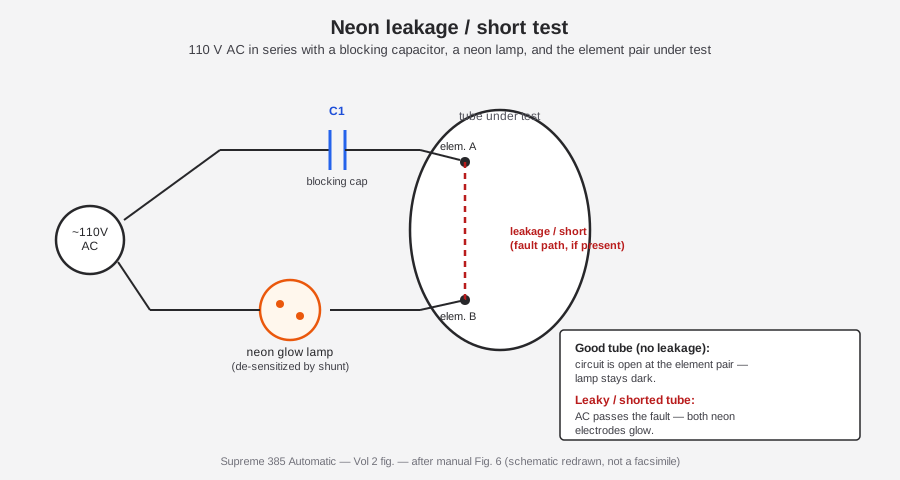
Per the manual’s Fig. 6, the leakage test loop is:
“110 V AC in series with a neon glow lamp, a blocking capacitor C₁, and the tube-element pair.”
That is a genuinely elegant minimal circuit. Walk the loop: 110 V AC feeds through the blocking capacitor C₁, into one socket contact (element “A” of the pair under test), and the return path is from the other socket contact (element “B”) through the neon glow lamp back to the AC source. In a good tube, elements A and B are not internally connected to each other — that is what “good” means for this test — so the loop is open at the tube and no current flows; the neon lamp stays dark. If a leakage path or short exists between A and B, AC current can now flow around the complete loop, through the neon lamp, and — because neon lamps glow at both electrodes once enough current passes regardless of which half-cycle is driving them — both electrodes of the neon lamp glow, giving the operator not just a fail indication but a visible cue of which element pair is at fault.
2.4.2 What the blocking capacitor is actually for
C₁’s job is subtler than “just block DC.” Its real purpose is to stop a tube that is merely doing its normal job as a rectifier from falsely triggering the test. Consider a rectifier tube, or any tube whose intended function involves conducting current from one element to another under some condition (a diode section, a grid drawing current under overdrive, etc.) — without the blocking capacitor in the loop, a tube that legitimately, correctly conducts between two elements under some part of the AC cycle could light the neon lamp even with zero fault present, because DC (or rectified AC) leakage current would complete the circuit just as effectively as a real short would. By putting a capacitor in series with the whole loop, only AC current — not a rectified DC component from a tube doing exactly what a rectifier tube is supposed to do — can complete the path and light the lamp. This is what lets the same test method be applied uniformly across every socket, every tube type, without the operator having to remember “don’t run the leakage test on rectifier tubes” as a special case.
2.4.3 Deliberately de-sensitized — and proud of it
The manual makes an unusually candid marketing argument here, worth flagging because it runs directly against the instinct to assume “more sensitive is always better”: the neon lamp in this circuit is deliberately shunted to reduce its sensitivity, so that the trivial, harmless leakage present in essentially every real tube (a few megohms of insulation-resistance imperfection that has no practical effect on circuit performance) does not trip a false “BAD” verdict. The manual goes further and directly criticizes rival testers that advertise extreme sensitivity as a selling point — the wording preserved in the facts record for this dive is that Supreme calls out competitors who brag their tester is “twenty times more sensitive,” framing that extra sensitivity as a liability, not an advantage, because it fails good tubes for leakage levels that don’t matter in a working radio.
This is a second small but real instance of the same engineering philosophy that shapes the whole instrument: Supreme consistently optimizes for a correct pass/fail verdict for a working serviceman on a working radio, not for laboratory-grade sensitivity or precision for its own sake. It is the same logic that chose emission over Gm for the main tube test, applied again to the leakage test.
Table 4 — Deliberately de-sensitized — and proud of it
| Test condition | AC path through the loop | Neon lamp | Verdict |
|---|---|---|---|
| Good tube, no leakage | Open circuit at the tube | Dark | Pass |
| Trivial/harmless leakage (typical of most real tubes) | Small AC current, below the de-sensitized threshold | Dark (deliberately) | Pass |
| Real leakage/short between tested elements | AC completes the loop | Both electrodes glow | Fail — leaky/shorted |
| Tube run hot, thermal soft-short develops | Loop closes only once hot | Glow appears after warm-up | Fail — heat-sensitive short |
The last row is why the manual lists “leakage while heated” as a distinct test item from cold leakage — some element-to-element faults only appear once the tube’s internal structure has thermally expanded into contact, which is exactly the kind of intermittent fault that drives a customer crazy in service and that a cold-only test would miss entirely.
2.5 The Copper-Oxide AC Voltmeter
The 385 is not only a tube tester; it is also a set analyzer and general-purpose VOM (Vol 1’s “combination instrument” framing). The AC-volts function of that VOM half is worth its own schematic-level look, because it is where the factory manual shows off its cleverest piece of circuit design — and because it directly answers the “what rectifier does this thing use” question that the original project scaffold got wrong.
2.5.1 No selenium — copper-oxide, and why that’s period-correct
The scaffold description this dive started from assumed a selenium rectifier. That is wrong, and it is wrong in a way that is easy to check against the calendar: selenium rectifiers only became a common component in US consumer and instrument electronics in the late 1930s and 1940s. A 1935 instrument reaches for the rectifier technology that was mature and cheap in 1935, which is copper-oxide — a metal-oxide junction rectifier used since the 1920s in AC instrument work specifically because, unlike a vacuum-tube rectifier, it needs no filament power and responds fast enough to track an AC waveform for metering purposes. The 385 uses copper-oxide for exactly one job: rectifying the AC-volts signal so the same 0–1 mA DC movement used everywhere else in the instrument can read it. The high-voltage DC power-pack function (ohms and capacitor tests, §5 below) is a completely separate circuit and uses a small thermionic rectifier tube, not copper-oxide and not selenium either.
2.5.2 The nonlinearity problem, and Supreme’s answer
Every AC-voltmeter-by-rectification design has the same fundamental headache: a rectifier’s forward resistance is not constant — it falls as current density rises, so a rectifier that behaves reasonably linearly at the higher end of its current range gets progressively less linear as the signal (and hence the current through it) shrinks. On a multi-range meter, this shows up as the lowest range being the least accurate, because it is the range where the rectifier is operating furthest into its nonlinear low-current region. A naive design — a plain resistor as the range multiplier on every range, sized purely by Ohm’s law — would therefore have its worst accuracy exactly where a technician most needs precision: reading small AC signals like a 5-volt heater winding or a low-level audio stage.
Supreme’s fix, and the circuit the manual clearly treats as a showcase design, is to replace the multiplier on the lowest (5 V) range with a series capacitor, C₁, used as a reactive multiplier instead of a resistor. A capacitor’s impedance is 90° out of phase with a resistor’s, and — critically for this application — using it as the series-limiting element keeps the copper-oxide rectifier operating closer to its rated current density even at low input voltages, which keeps the rectifier in a more linear part of its own curve. The manual states the measured result directly: this trick cuts the 5 V-range error from roughly 5.8% down to roughly 1.3% — better than a fourfold improvement, on exactly the range where a resistor-only design would have been weakest.
The higher ranges (25/125/250/500/1250 V) don’t need the same trick — at those signal levels the rectifier is comfortably in its linear region on ordinary resistor multipliers — but they get a second, smaller refinement: parallel trimming capacitors, C₂ through C₆, one associated with each higher range, which correct for the difference between the meter’s RMS-calibrated scale and the rectifier/meter combination’s true response to a sine wave. That correction factor, cited directly in the manual, is the standard 1.11 RMS-to-average-value form factor for a sine wave through a full-wave rectifier — the trim caps nudge each range’s reading back onto that 1.11 relationship so the scale reads true RMS volts rather than whatever the raw rectified-average current would otherwise indicate.
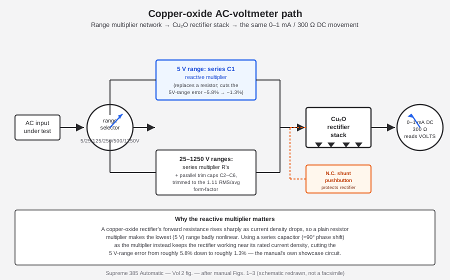
Table 5 — The nonlinearity problem, and Supreme's answer
| Range | Multiplier element | Why |
|---|---|---|
| 0–5 V AC | Series capacitor C₁ (reactive multiplier) | Keeps the copper-oxide rectifier near its rated current density at low signal levels; cuts error from ~5.8% to ~1.3% |
| 0–25 V AC | Series R + parallel trim cap C₂ | Trims to the 1.11 RMS/average form factor |
| 0–125 V AC | Series R + parallel trim cap C₃ | ” |
| 0–250 V AC | Series R + parallel trim cap C₄ | ” |
| 0–500 V AC | Series R + parallel trim cap C₅ | ” |
| 0–1250 V AC | Series R + parallel trim cap C₆ | ” |
2.5.3 Protecting the rectifier itself
Copper-oxide rectifiers are not immune to overload — a surge can punch through the thin oxide junction and degrade or destroy the rectifying layer permanently, which on this instrument would throw off every AC-volts range at once (and the capacitor tests, which also route through this same rectifier — see §5). The manual describes two independent protective measures, listed under Quick-Facts item 14, “Positive rectifier protection”:
- The rectifier is switched entirely out of circuit except when an AC-volts or capacity range is actively selected — on every other function (DC volts, DC mA, ohms, the tube tests) it simply isn’t in the signal path, so it can’t be damaged by whatever is happening on those other functions.
- A normally-closed pushbutton shunts the rectifier input — meaning the default, at-rest state of the circuit is a dead short across the rectifier’s input terminals that any surge harmlessly dumps into, rather than driving it into the rectifier. The operator has to deliberately press and hold the button open to actually connect the rectifier into the measuring circuit, and the shunt snaps back closed the instant the button is released.
On top of both of those, a 1-A fuse in the transformer primary is the last-resort protection for the instrument as a whole, catching any fault severe enough to pull excessive current from the mains regardless of which internal function was active when it happened.
⚠ Danger — copper-oxide rectifiers this old are known to age — their forward resistance rises with decades of service, which throws off AC-volts calibration well before the rectifier fails outright. Vol 5 covers testing and, if necessary, sourcing a replacement; the short version is do not substitute a selenium or silicon rectifier here without a full recalibration — the entire multiplier/trim-cap network above (C₁ especially) was trimmed to this specific rectifier’s current-density curve, and a different rectifier technology has a different curve.
2.6 The Rectifier-Tube Power Pack — DC Ohms and Capacitor Tests
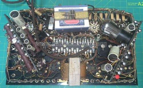
The AC-voltmeter’s copper-oxide rectifier is not the only DC source inside the 385. The high-ohms ranges and the capacitor tests need a real, filtered DC supply of their own, and for that Supreme built a small self-contained “power pack” around a thermionic rectifier tube — the manual’s Fig. 9 shows a small triode, read from the scan as an 01A-class tube type (not stated in plain text on the surviving copy, so treat the exact type as a well-supported reading rather than a confirmed part number), feeding a 4-mfd filter capacitor off a dedicated ~350 V transformer winding.
2.6.1 The ohmmeter: two sources for six ranges
The 385’s resistance function splits its six ranges across two entirely different power sources, which is worth noting because it means “the ohmmeter” is really two different circuits sharing one meter scale:
Table 6 — worth noting because it means "the ohmmeter" is really two different circuits sharing one meter scale
| Ranges | Source | Notes |
|---|---|---|
| Low four ranges | Self-contained flashlight battery (nominally ~1.5 V) | Same battery doubles as the “grid-shift” point-test source for in-circuit analyzer checks (§6). This is the battery collectors most often report missing on a found unit. |
| 0–2 MΩ, 0–20 MΩ (the two high ranges) | The rectifier-tube power pack | A ~350 V winding through the rectifier tube and its 4-mfd filter gives the higher open-circuit voltage a megohm-range ohmmeter needs to push a measurable current through a large resistance. |
On the lowest scale, the finest division the meter face resolves is ¼ Ω, with half-scale deflection at 15 Ω on the 0–200 Ω range — figures the manual states directly and that give a sense of just how much range-switching and multiplier engineering is packed behind the single physical meter movement. Fig. 10 also shows an electrical “Zero Adjuster” specific to the ohms function, used to null the meter to full-scale (zero ohms) after the battery has aged or after a recap — Vol 5 covers using it as part of the calibration sequence.
2.6.2 The capacitor tests: two different verdicts for two different fault modes
Capacitor testing on the 385 splits the same way emission and leakage split for tubes — one test for “does it hold a good value,” one test for “does it leak” — and, tellingly, it reuses circuit ideas from both the tube-test and the AC-voltmeter sections rather than inventing new ones:
- Electrostatic (film/paper/mica) capacitors — leakage test. DC from the rectifier-tube power pack, through a current-limiting resistor, is applied to the capacitor under test; the same neon-lamp principle from §3 reads leakage — a capacitor that should be blocking DC but instead passes a leakage current lights the lamp, exactly as a leaky tube element pair does.
- Electrolytic capacitors — condition test. Electrolytics are different enough (higher expected leakage is normal for the technology, and capacitance value matters as much as leakage) that they instead get a dedicated GOOD/BAD verdict on the meter’s upper arc — the same right-hand meter that carries the tube GOOD/?/BAD scale, just a different arc on the same dial (see the meter-face table in §1).
- Capacitance value (0.001–12.5 mfd, six ranges). Separately from the leakage/condition checks, the capacity-value ranges use dedicated low-voltage transformer taps — the manual’s Fig. 3 shows taps around 4.5 / 9.5 / 22.5 V feeding this function — combined with the same neon-indication principle to establish value against a reference.
Table 7 — The capacitor tests: two different verdicts for two different fault modes
| Function | DC/AC source | Readout | Circuit idea reused from |
|---|---|---|---|
| Electrostatic cap leakage | Power-pack DC | Neon glow | §3 (tube leakage test) |
| Electrolytic cap condition | Power-pack DC | GOOD/BAD meter arc | §1 (tube meter arc, opposite side) |
| Capacitance value (6 ranges, 0.001–12.5 mfd) | Dedicated low-V transformer taps (~4.5/9.5/22.5 V) | Neon-referenced value read | — (dedicated taps) |
This reuse is worth pausing on as a piece of engineering economy: rather than design a fourth distinct measuring principle for capacitors, Supreme’s engineers recognized that “does current leak where it shouldn’t” (the tube-leakage neon trick) and “does the meter read GOOD or BAD against a fixed threshold” (the tube-quality meter arc) were both already-solved problems on this chassis, and simply pointed the same circuits at a different two-terminal device.
2.6.3 The complete power supply picture
Putting the AC-voltmeter’s copper-oxide path (§4) and the power pack’s rectifier tube (this section) together with the raw transformer windings gives the full power-supply map for the instrument:
Table 8 — with the raw transformer windings gives the full power-supply map for the instrument
| Winding / source | Approx. voltage | Feeds |
|---|---|---|
| Primary | 98–125 V, 60-cycle (rated), 1-A fuse | Whole instrument |
| Filament secondary (multi-tapped) | Taps roughly in the 98–125+ V range per the Fig. 13 scan (not every tap fully legible) | Filament Volts Selector → tube-under-test heater/filament |
| Low-voltage taps | ~4.5 / 9.5 / 22.5 V | Capacitance-value reference potentials |
| Neon-test winding | ~110 V AC | Leakage/short test loop (§3) |
| Power-pack winding | ~350 V | Rectifier tube → DC ohms (2/20 MΩ) and capacitor DC supply |
| Flashlight battery | ~1.5 V (nominal) | Low-ohms ranges, grid-shift point test |
| Secondary battery (per Fig. 10 zero-set) | ~4.5 V | Ohms zero-adjust reference |
The filament-tap voltage list deserves a caveat: the scan of Fig. 13 that this figure is drawn from does not resolve every tap cleanly, so treat the “roughly 98–125+ V” span as the best reading available rather than a confirmed complete list — Vol 3’s hardware inventory and Vol 5’s service notes are the places to record any additional taps confirmed by direct inspection of Jeff’s own unit.
2.7 The Analyzer and VOM Functions, Briefly
The full operating procedure for the analyzer/VOM side of the 385 belongs to Vol 4; this section closes the circuit-theory picture only far enough to show that every VOM function still routes through the same two meter movements and the same handful of building blocks already described above — there is no separate “VOM circuit” hiding elsewhere in the chassis.
- DC volts (0/5/25/125/250/500/1250 V): the 0–1 mA movement directly, through switched series multiplier resistors — no rectifier needed, since the input is already DC.
- DC milliamps (0/5/25/125/250/500/1250 mA): the same movement, through switched parallel shunt resistors (Fig. 12) instead of series multipliers — shunts divert the bulk of the current around the meter rather than adding series resistance in front of it.
- AC volts / output (0/5/25/125/250/500/1250 V): the copper-oxide path detailed in §4.
- Resistance (6 ranges, ¼ Ω–20 MΩ): the split battery/power-pack sourcing detailed in §5.
- Set analysis (in-circuit): the manual’s “Free Reference Point System of Analysis” — an analyzing cable/plug that connects into the radio-under-test’s own tube sockets, combined with a self-contained “grid-shift” battery (the same low-voltage battery used for the low ohms ranges) for spot-checking a tube while it remains installed in a customer’s chassis. This in-circuit “grid-shift” check is a crude, battery-powered relative of the Gm principle — a small signal/bias perturbation and a current reading — but it is not the 385’s own-socket bench test, and it is not built or calibrated to the standard a dedicated Gm instrument like the TT-1 requires (Vol 1 flags this distinction; it bears repeating here because it is the one place in the whole instrument where the emission/Gm line gets genuinely blurry). The bench Quality Test — the headline tube-test function this instrument is built and sold around — remains emission, full stop.
- Circuit-breaking twin jacks on the analyzer section are the mechanical trick, not a separate electrical function: a jack pair that only completes its circuit once both plugs are inserted, which is what lets the analyzer give “automatic current measurements” (Vol 1’s framing of “Automatic”) without a pushbutton for every single measurement type.
2.8 Sources {.unnumbered}
- Supreme Instruments — “The New Supreme Model ‘385 Automatic’ Tester,” factory technical manual /
Radio Craft reprint, 13 pp. (Figs. 1–13 schematics; “385 Quick-Facts” back cover with meter-scale
descriptions and price).
https://stevenjohnson.com/supreme/data/supreme385-manual.pdf - Supreme Instruments archive downloads (385 Technical Manual, early Instructions & Tube Data Sheet,
“89 series and 385 Tube Data,” “1939 Updated Tube List”):
http://www.supremeinstruments.org/data.htm - Radiomuseum, “Automatic Tube Tester 385, Supreme Instruments” (date, price, photo set):
https://www.radiomuseum.org/r/supreme_in_automatic_tube_tester_385.html - Supreme Instruments Corp. company history:
http://www.supremeinstruments.org/history.htm - Steven Johnson, “Supreme Tube Testers and Radio Analyzers” — consulted for context only; its “385 =
transconductance” entry contradicts the factory manual and is not relied upon in this volume:
https://stevenjohnson.com/supreme/tubetesters.htm - EDN, “What’s It Worth: Supreme Instruments — Function Meets Art” (company history, design ethos):
https://www.edn.com/whats-it-worth-supreme-instruments-function-meets-art/ - Sibling volume: Heathkit TT-1 Tube Tester, Vol 2 — the mutual-conductance circuit that completes this pairing.