Supreme Instruments 385 Automatic Tester · Volume 3
Supreme 385 Automatic — Vol 3: Inside This Unit — Hardware, Meter, Sockets & Setup
Two fan-shaped meters, five no-adapter sockets, three rotary knobs, and a power pack with no selenium in sight — the physical instrument behind the 1935 marketing name.
3.1 What’s under the lid
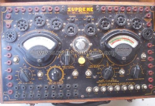
Open the wood carrying case of a Supreme “385 Automatic” and the first thing that registers is not a mechanism — it’s a layout. There is no drum to spin, no chart to crank past a window, no single master knob promising to configure the whole instrument for you. What’s there instead is a bakelite panel dominated by two big fan-shaped meter faces, a cluster of five tube sockets, and three unassuming rotary switches sitting between them. Vol 1 §2 and Vol 2 walk through why Supreme built it this way — this volume is the parts list: what each control is, what each meter face reads, how the sockets are wired to take five different tube-pin counts without a single adapter, and where the power for all of it comes from.
Read this volume as the reference you’ll want open next to the unit on the bench. Vol 4 covers the step-by-step procedure for grading a tube; here we’re cataloguing the hardware that procedure walks you through.
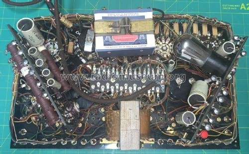
⚠ Danger — mains-powered antique. Everything described in this volume sits behind a bakelite panel that was never designed with a modern polarized plug, a ground pin, or a GFCI outlet in mind. Several points on the chassis — the ~350 V winding, the neon-test’s ~110 V AC feed, the primary side of the transformer — can be at lethal potential relative to the case or to earth. Treat every internals photo and every schematic reference in this volume as look, don’t touch until you’ve read the safety discipline in
_shared/legal_ethics.mdand the bring-up procedure in Vol 5.
3.1.1 Case and chassis
The 385 ships in a wood carrying case with a hinged lid, a fitted bakelite front panel screwed to the case front, and a chassis bolted behind the panel carrying the transformer, the meter movements, the rotary wafer switches, the rectifier hardware, and the miniature power-pack tube. Reported case dimensions disagree between the two secondary sources this dive draws on — stevenjohnson.com gives roughly 18 × 13¼ × 6½ in, radiomuseum gives roughly 18 × 7 × 14 in — the width (~18 in) and the weight (≈ 22 lb) are the only figures both sources agree on, so treat the depth/height split as unresolved rather than pick one. What’s not in dispute: this is a carry-to-the-customer’s-house instrument, not a bench-bolted rack unit — a service tech in 1935 was expected to pick this thing up by its handle and take it on a call.
3.1.2 The panel at a glance
Table 1 — 1.2 The panel at a glance
| Zone | What’s there | Covered in |
|---|---|---|
| Upper-left | Left 5-in fan meter (OHMS / VOLTS-MA-MFDS) | §2 |
| Upper-right | Right 5-in fan meter (tube GOOD/?/BAD, capacitor GOOD/BAD) | §2 |
| Center strip | Filament Voltage Selector, Filament Return Selector, Quality Test Selector (three rotary knobs) | §4 |
| Lower panel | Five tube-test sockets (4-, 5-, 6-, 7-, 8-pin) + top-cap terminal | §3 |
| Lower panel, analyzer side | Circuit-breaking twin jacks, range switches for volts/ma/ohms/mfd, rectifier-shunt pushbutton | Vol 2 §2, §6.6 below |
| Lid | Printed “Tube Testing Operating Data” / Tube List card | §7 |
| Chassis rear | Power transformer, rectifier tube socket, copper-oxide rectifier stack, primary fuse holder, line cord | §5, §6 |
3.1.3 Panel material and house style
The front panel is bakelite, not painted sheet metal — a material choice that let Supreme engrave or silk-screen crisp white lettering and scale artwork directly into a dark, glare-resistant surface, rather than relying on paint that would chip and wear at the edges of a rotary control after a few hundred service calls. Trade press coverage of Supreme’s design language (EDN’s later retrospective on the company) frames this as deliberate: the firm built instruments to be “functional and beautiful” at the same time, and the fan meters, the panel engraving, and the overall symmetry of the layout are all part of a consistent house aesthetic that ran across Supreme’s whole product line in this era, not just the 385. Vol 1 §1 covers the company-history side of that story; here it’s enough to note that the panel you’re looking at was styled on purpose, not simply laid out to fit the parts.
3.2 The two 5-inch fan meters
3.2.1 One movement, two jobs
Both meters on the 385’s panel are the same basic movement: a 5-inch, fan-shaped d’Arsonval type, 0–1 mA DC full scale, 300 Ω internal resistance. Supreme’s own copy calls this out as a selling point — “Exclusive design 5-in. Supreme fan-type meters” — and the factory manual’s Fig. 11 labels the movement explicitly: “300 OHMS – Rm, 0–1 M.A. D.C. METER.” There is no separate “tube meter” and “volt meter” inside the case; there are two identical galvanometers, and the rest of the instrument’s cleverness is in the switching network of multipliers and shunts wrapped around each one.
That’s the “uni-construction” idea the manual leans on: a single 0–1 mA movement, properly multiplied and shunted, can stand in for roughly 32 single-range meters. Two of them — one dedicated to the analyzer/VOM functions, one dedicated to the tube-quality and capacitor verdict — cover the whole instrument’s readout needs without a bank of separate meters cluttering the panel. The fan shape itself is a Supreme house signature (see Vol 1 §1 for the “function meets art” design language) as much as it is functional — a wide fan gives more usable arc length per unit panel space than a round dial of the same diameter, which matters when you’re trying to resolve a GOOD/?/BAD verdict on a 0–100 scale by eye in a customer’s dim living room.
3.2.2 Left meter — the analyzer/VOM face
The left meter carries the instrument’s general-purpose measuring scales:
- An outer OHMS arc, non-linear in the usual ohmmeter way (compressed at the high-resistance end, expanded near mid-scale).
- An inner “VOLTS – MILLIAMPERES – MFDS” arc — the shared linear scale that the range switch (Vol 2 §2) reinterprets according to which function and range is selected.
This is the meter you read for DC volts, AC volts, DC milliamps, resistance, and capacitance — everything except the tube-quality and capacitor-condition verdicts, which live on the right meter. Table 2.1 lists the ranges this meter supports as configured by the rest of the instrument (the switching and multiplier networks that make each range possible are Vol 2 §2’s territory, not this volume’s — here we’re only cataloguing what the meter face itself shows).
Table 2.1 — Left-meter (analyzer) ranges
Table 2 — Table 2.1 — Left-meter (analyzer) ranges
| Function | Ranges | Notes |
|---|---|---|
| DC volts | 0 / 5 / 25 / 125 / 250 / 500 / 1250 V | Direct multiplier chain off the 0–1 mA movement |
| AC volts / output | 0 / 5 / 25 / 125 / 250 / 500 / 1250 V | Via the copper-oxide rectifier, §6.2 |
| DC milliamps | 0 / 5 / 25 / 125 / 250 / 500 / 1250 mA | Shunt network, Fig. 12 of the manual |
| Resistance | 6 ranges, ¼ Ω to 20 MΩ | Low 4 ranges from the flashlight battery; high 2 ranges (0/2/20 MΩ) from the rectifier-tube power pack, §6.3 |
| Capacitance | 0.001–12.5 mfd, 6 ranges | Electrostatic value; separate leakage/condition path below |
3.2.3 Right meter — the tube and capacitor verdict face
The right meter is where the “Automatic” name earns its keep on a bench level — it’s the meter you glance at, not read closely, because the scale is designed to be interpreted at a distance:
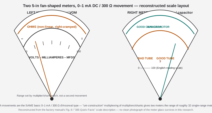
- A top arc reading “GOOD CAPACITOR … BAD CAPACITOR” — the electrolytic-condition verdict.
- A lower arc reading “BAD TUBE … ? … GOOD TUBE” over a 0–100 English-reading scale — the tube-quality (emission) verdict.
The factory manual’s own language for this is deliberate: item 19 of the Quick-Facts sheet promises the instrument “accurately classifies all tubes as ‘Good’ or ‘Bad’ on English Reading scale.” That phrase — “English reading” — is period jargon for a scale you can interpret without translating a number against a reference chart: no µmhos, no percentage-of-rated-Gm lookup, just a needle that swings into a green zone, a red zone, or the doubtful ”?” between them. It’s the emission method’s whole ergonomic promise (developed at length in Vol 2 §1–§2): fast, unambiguous, operator-proof, at the cost of only ever answering “does the cathode still emit,” never “how much gain does this tube still have.”
Cross-reference — the pairing theme. This GOOD/?/BAD needle sweep is the visual signature of emission testing. Its opposite number on Jeff’s bench, the Heathkit TT-1, reads out a transconductance figure in micromhos on a linear scale that the operator then compares against a printed minimum-Gm chart per tube type — a fundamentally different reading experience for a fundamentally different measurement. See the Heathkit TT-1 dive and Vol 6 §1 of this dive for the two-tester comparison.
No clean photograph of the meter glass survives among the sources gathered for this dive — the radiomuseum photo set and the manual scan both show the panel from angles or resolutions that don’t resolve the scale artwork cleanly enough to reproduce. Figure 3.1 below is a reconstruction of the scale layout from the factory manual’s Fig. 8 discussion and the “385 Quick-Facts” back-page description, not a traced copy of an original photograph — treat the exact tick spacing and typography as illustrative, not a facsimile.
Figure 3.1 — Reconstructed meter scale faces
3.2.4 Why fan-shaped, not round
It’s worth pausing on the mechanical logic of the fan shape rather than treating it purely as styling. A conventional round meter dial wastes panel area in its corners — the useful scale arc is a fraction of the full circle, and the rest of the round bezel is just frame. A fan-shaped meter throws away that unused area and devotes the entire panel footprint to scale arc, which is exactly what the 385 needs: two scales stacked on one right-hand meter face (capacitor verdict on top, tube verdict below) and two scales sharing one left-hand meter face (ohms outer, volts-mA-mfd inner). Cramming four distinct scale arcs onto two meter faces, at a size still readable from arm’s length in a customer’s living room, is a genuine design constraint the fan shape solves better than a round dial would — the “house style” argument in §1.3 and the ergonomic argument here point at the same design decision from two different angles.
3.2.5 Meter protection
Both meters share the instrument’s overload philosophy. For the tube-quality (Quality Test) circuit specifically, the manual states that when the Quality-Test selector is correctly set for a given tube type, the external circuit resistance is engineered to be about 10% of the total circuit resistance including a normal tube in circuit — meaning a fully shorted tube can impose at most roughly a 10× overload on the meter circuit, a figure the design is stated to survive without damage (“both meters fully protected”). On the AC-voltmeter side, the copper-oxide rectifier itself gets a dedicated protection scheme (§6.6) rather than relying on the meter movement alone. This overload tolerance is part of why the manual can promise, as one of its headline claims, that “a tube cannot be placed in the wrong tube-testing socket, nothing happens if the wrong button is depressed, and the tester cannot be harmed by an incorrect selector setting or by a ‘shorted’ tube.”
3.3 Five sockets, no adapters
3.3.1 The universal socket set
The 385’s tube-test area holds five separate sockets, sized for 4-pin, 5-pin, 6-pin, 7-pin, and the (then brand-new) 8-pin octal metal-tube base — plus a top-cap terminal for grid-cap tubes. Quick-Facts item 21 states it plainly: “Only 5 sockets for tube testing — no adapters — including 8-pin metal tubes.” This was a genuine claim to novelty in 1935: RCA’s metal-envelope octal tubes were brand new that year, and the manual makes a point of billing the 385 as “probably the first tester to be announced for complete tests of all 8-pin tubes.” No snap-in adapter shells, no adapter-loss risk on a service call, no adapter-contact-resistance error creeping into the emission reading — the socket that fits the tube is simply there.
Table 3.1 — The five tube-test sockets
Table 3 — Table 3.1 — The five tube-test sockets
| Socket | Pin count | Era context (general — not 385-specific in the source documents) | Notes |
|---|---|---|---|
| 4-pin | 4 | The oldest base family in service by 1935 — early two-, three-, and four-element battery and AC tubes | Oldest base style the 385 supports |
| 5-pin | 5 | Mid-1920s–early-1930s base family, common on early screen-grid types and small rectifiers | |
| 6-pin | 6 | Six-pin base family current through the mid-1930s | |
| 7-pin | 7 | Seven-pin base family, the immediate predecessor generation to the octal | |
| 8-pin (octal) | 8 | The new metal-envelope tubes RCA had just announced in 1935 | 45° pin ring — see §3.2; billed as the headline feature |
| Top cap | 1 (separate terminal) | Grid-cap tubes of any base type above | Not a socket — a clip/terminal reached over the tube |
The manual does not spell out, tube type by tube type, which specific 1930s base families map to which of the five sockets — that mapping lived on the Tube List card (§7), not in the technical manual’s prose. The “era context” column above is general radio-history background for orientation, not a quote or figure taken from the 385’s own documentation.
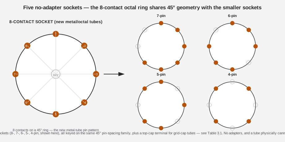
3.3.2 The 45° geometry trick
The 8-contact octal socket is more than “one more socket size” — its geometry is why the whole socket family can claim “no adapters” in the first place. The manual explains that because the new metal tubes use pin spacing at 45° multiples around the base circle, a tube with fewer pins (7-, 6-, 5-, or 4-pin) simply drops into a socket wired on that same 45°-family geometry, leaving the unused contact positions blank rather than requiring a different, incompatible pin circle for every base size. In practice this means the 385’s socket family is a set of sockets that share a consistent keying logic — a tube physically cannot be forced into a socket sized for a different base, and no contact position sits ambiguously between two possible pin roles. That’s the mechanical half of “the tester cannot be harmed… by an incorrect selector setting or a ‘shorted’ tube”: the socket geometry itself prevents a lot of the wrong-hookup failure modes that plagued testers relying on universal 8- or 9-pin sockets plus a pile of add-on adapter shells.
Figure 3.2 — Socket geometry
3.3.3 What the sockets do not do
It’s worth being explicit about a common assumption this dive had to correct against the project scaffold (see Vol 1 §3 for the full contradiction discussion): the sockets are not selected by a single rotary knob, and there is no rotating drum or roll chart that reconfigures socket wiring for you. Each of the five sockets is a fixed, independently wired socket on the panel; you physically insert the tube into whichever one matches its base. What is automatic is everything downstream of that physical choice — the current-metering path, the leakage-indication path, and the overload tolerance described in §2.5. The “Automatic” name markets the no-adapter, no-wrong- socket, no-pushbutton-current-reading combination, not a tube-selecting mechanism. That distinction matters enough to the whole dive that it gets its own callout:
Correction — no drum, no roll chart, no selection knob. If you’ve seen the 385 described elsewhere as having “single-knob rotary tube-selection… replacing pin-switch banks” or a “roll chart,” that description belongs to later Supreme testers (the roll-chart-equipped 500-series arrived in the late 1930s) — not this instrument. On the 385, setup is three independent rotary knobs (§4) set from a printed card (§7), and tube selection is simply picking the correct physical socket.
3.3.4 The top-cap terminal
Fig. 13 of the manual shows a dedicated “Tube Test Top Cap” terminal alongside the five sockets — a spring clip or lead reached up and over the tube envelope to contact its top-cap grid connection, standard practice for the era’s grid-cap tubes (a common construction through the mid- 1930s for tube types that routed the control grid to a top cap rather than a base pin, before that connection migrated onto the base with the octal generation). This terminal isn’t a sixth “socket” in the pin-count sense; it’s a supplementary connection point used in addition to whichever base socket the tube’s other elements go into.
3.4 The three setup knobs
Where a later “Automatic”-branded tester from a different maker might spin one big rotary dial labeled with tube type numbers, the 385 hands you three separate, purpose-built rotary selectors. Each does one job; together they establish the electrical conditions the Tube List card specifies for a given tube type before you ever look at the meter.
Table 4.1 — The three rotary setup controls
Table 4 — Table 4.1 — The three rotary setup controls
| Control | What it sets | Why it exists |
|---|---|---|
| Filament Voltage Selector | Which tap of the multi-tapped filament transformer secondary feeds the socket’s heater/filament pins | Different tube types run filaments/heaters anywhere from roughly 1.5–2.5 V (battery types) up past 100+ V (series-string AC/DC heater strings) — one fixed filament voltage cannot serve them all |
| Filament Return Selector | Which socket pin the filament/heater return connects to | Different base standards put the second filament/heater pin in different positions; this selector is what lets one physical socket serve tube types whose heater-return pin varies |
| Quality Test Selector | The value of the variable load resistor in the emission-test circuit | Sets the per-tube-type load the Quality Test current is measured through — see Vol 2 §2 for the full emission-circuit derivation |
3.4.1 Filament Voltage Selector
The filament/heater supply comes off a multi-tapped secondary winding on the power transformer (§5). The manual’s Fig. 13 shows a long run of taps — values including roughly 98/101/104/107/110/113/116/119/122/125 V and others extend the range further — selected by turning the rotary Filament Volts Selector to the tap the Tube List card specifies for the tube under test. Because filament/heater ratings across the era’s tube population range from small battery-tube filaments up through AC heater strings, this is effectively a coarse-to-fine voltage-select switch sitting directly in the heater supply path, not a variac-style continuously variable control.
3.4.2 Filament Return Selector
This is the control that makes “one socket per pin-count, no adapters” actually work in practice. Not every tube base standard puts the second filament/heater connection on the same physical pin — so a fixed-wiring socket that assumed a single “filament return” pin position would fail on tubes whose base assigns that role elsewhere. The Filament Return Selector routes the return side of the filament/heater circuit to whichever pin position the Tube List card calls for, decoupling “which socket does this tube’s pin count need” (fixed by the socket itself, §3) from “which pin on that socket carries the filament return” (variable, handled by this selector).
3.4.3 Quality Test Selector
The third knob is the one that actually shapes the emission measurement itself. Per the manual’s Fig. 5 discussion:
“the direct current passed by the tube is measured by one of the meters … the current is limited by the tube and two resistors, one of which is variable. The value of the variable resistor is predetermined for each type of tube, and the corresponding control-knob setting is included in a ‘TUBE LIST’ card which accompanies each tester.”
The Quality Test Selector is that variable resistor’s control knob. Setting it to the value the Tube List card specifies for a given tube type establishes the load the tube’s emission current is read through, which in turn is what calibrates the meter’s GOOD/?/BAD needle position to mean something consistent across wildly different tube types (a power pentode and a small battery triode draw very different currents at “healthy,” and this knob is what normalizes the reading against each type’s expected load). The full circuit-theory derivation of why this load produces a meaningful emission reading, and the 10%-of-total-resistance overload-protection argument introduced in §2.5, both belong to Vol 2 §2 rather than repeating here — this volume’s job is simply to identify the knob and what turning it does.
3.4.4 Why three knobs, not one
It’s tempting to read “Automatic” and expect a single master control, so it’s worth stating plainly why the 385 uses three: each knob independently addresses a different physical variable (heater voltage level, heater return pin position, and emission-test load), and those three variables don’t covary predictably across the era’s tube population — two tubes needing the same filament voltage can need different filament-return pins, and two tubes needing the same filament-return pin can need very different Quality Test loads. Collapsing all three into one knob would require either an impractically large number of discrete positions (one per tube type, which is closer to what a later roll-chart/drum tester attempts) or giving up the fine-grained per-type accuracy the manual is proud of. Three knobs plus a lookup card is the tradeoff Supreme chose in 1935; see Vol 4 §1 for how this actually plays out as a bench procedure.
3.4.5 Why the three knobs can’t be collapsed — a hardware-level illustration
It’s easier to see why three independent controls are necessary, rather than merely traditional, by holding two hypothetical tube types side by side against the hardware described in §3–§4:
- Tube Type A, a small battery-filament triode, and Tube Type B, an AC-heater output pentode, might both happen to use the same physical socket (matching pin count) — but Type A needs a low filament-supply tap from the low end of the transformer’s tapped secondary (§5) while Type B needs a tap from the high end. Same socket, different Filament Voltage Selector position.
- Two tube types that both need the same filament voltage tap can still disagree about which pin carries the filament return, because base standards weren’t perfectly consistent about where that connection sits — hence a separate Filament Return Selector rather than folding return routing into the voltage tap choice.
- Two tube types that agree on both filament voltage and return pin can still be built around entirely different cathode/plate geometries and rated currents, which is exactly what the Quality Test Selector’s variable load resistor exists to normalize — see the load-resistor derivation in Vol 2 §2.
No single rotary switch position can encode all three of those independent facts about a tube type at once without effectively becoming a giant per-tube-type lookup table wired into the switch itself — which is a fair description of what a later roll-chart/drum tester’s mechanical linkage actually does, at a cost and complexity the 385’s designers were explicitly trying to avoid (Vol 2 §1’s discussion of the manual’s own cost argument against a fully mechanized Gm tester makes the same trade-off calculation from a different angle).
3.5 The filament transformer
The filament supply is worth a short section of its own because it’s the one part of the power system whose job is purely to serve the tube-under-test rather than the instrument’s own metering functions.
Table 5.1 — Filament transformer secondary (approximate, per Fig. 13)
Table 5 — Table 5.1 — Filament transformer secondary (approximate, per Fig. 13)
| Characteristic | Value | Confidence |
|---|---|---|
| Type | Multi-tapped secondary winding on the main power transformer | Confirmed |
| Selector | Rotary “Filament Volts Selector,” panel-mounted | Confirmed |
| Representative taps shown in Fig. 13 | ~98 / 101 / 104 / 107 / 110 / 113 / 116 / 119 / 122 / 125 V, and further taps beyond this run | Confirmed (values legible on the scan) |
| Full span (battery-tube low end through AC heater-string high end) | Roughly 1.5–2.5 V up to values referenced against the ~117 V line | Likely — some taps not fully legible on the manual scan |
| Return routing | Selected independently by the Filament Return Selector (§4.2) | Confirmed |
Two things are worth flagging for anyone tracing this section against the manual scan directly. First, the exact minimum and maximum taps aren’t fully legible in the source PDF — treat the “full span” row above as the shape of the range, not a precise spec. Second, don’t confuse this tapped filament winding with the transformer’s other, higher-voltage windings (the ~110 V neon-test feed and the ~350 V rectifier-tube-supply winding) covered next in §6 — they’re physically separate windings on the same core, doing unrelated jobs.
3.6 Power supply — copper-oxide rectifier, not selenium
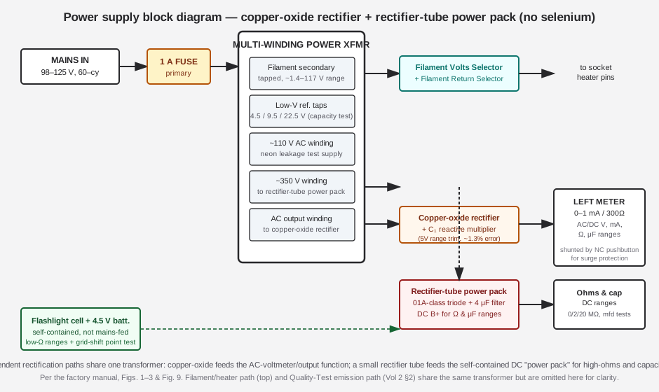
3.6.1 Two independent rectification paths
This is the section that most directly overturns an assumption baked into the original project scaffold, so it’s worth stating up front and in bold: the 385 has no selenium rectifier. Selenium rectifiers only became common in US consumer and instrument gear in the late 1930s–1940s; a 1935 instrument rectifying at all is going to use either a vacuum tube or a copper-oxide stack, and the 385 uses both, for two different jobs:
- A copper-oxide instrument rectifier feeds the AC-voltmeter/AC-output function — the path that lets the left meter (§2.2) read AC volts on the analyzer.
- A rectifier tube, inside a small self-contained “power pack,” feeds the DC supply used for the high-ohms ranges (0/2/20 MΩ) and the capacitor tests.
These are not redundant or alternative rectifiers — they’re two separate circuits built around two different rectification technologies, chosen because the two jobs have different requirements (an AC-voltmeter rectifier needs to be linear and low-loading; a DC power-pack supply needs enough voltage and current to drive an ohmmeter and a capacitor tester through a real load).
Figure 3.3 — Power supply block diagram
3.6.2 AC voltmeter path — copper-oxide
The copper-oxide rectifier converts the AC being measured into a DC current the 0–1 mA movement can read, but copper-oxide rectifiers of this era have a well-known nonlinearity problem: their forward resistance is current-density-dependent, so a simple resistive multiplier produces increasing error as you move down toward the low-voltage end of a multi-range voltmeter. Supreme’s fix, and one the manual treats as a showcase circuit, is to use a series capacitor (C₁) as a reactive multiplier on the lowest (5 V) range instead of a resistor — a capacitive reactance sits roughly 90° out of phase with the rectifier’s nonlinear resistive behavior, and the manual reports this cuts the 5 V-range error from about 5.8% down to about 1.3%. The higher ranges use parallel trimming capacitors (C₂–C₆) to correct for the standard 1.11 RMS-to-average form-factor relationship a rectifier-type AC meter has to account for. This C₁ network isn’t just a bypass component — the manual makes it an explicit calibration element, which matters directly for Vol 5’s recap-and-calibrate procedure: replacing C₁ with an off-value substitute during a recap will shift the 5 V AC range’s calibration, not just its ripple filtering.
3.6.3 DC power-pack path — rectifier tube
The second rectification path is a small, self-contained “power pack” built around a rectifier tube (Fig. 9 of the manual shows a triode consistent with an 01A-class type, though it isn’t labeled in plain text on the scan — treat the exact tube type as likely-but-not-certain). This circuit takes the transformer’s ~350 V winding, rectifies it, filters it through a roughly 4 mfd capacitor, and delivers the DC supply that powers:
- The two high-ohms ranges (0/2/20 MΩ) of the ohmmeter function — the low four ranges instead come from a self-contained flashlight battery, entirely independent of the mains-derived power pack (§6.5 below).
- The DC current used in the capacitor tests, run through a current-limiting resistor to the device under test.
This is the “power pack” the facts source and the manual both refer to by that name — a self-contained miniature B+ supply riding inside the same case as everything else, doing for the ohmmeter/capacitor functions what a separate bench power supply would otherwise have to do.
3.6.4 Mains input and primary protection
The instrument is rated for 98–125 V, 60-cycle mains (“For 98–125 volt, 60-cycle. Special voltage or frequency instruments can be supplied at slight additional cost” per the manual’s back page) and protects its primary with a 1-A fuse. There’s no polarized plug and no ground pin — period-correct for 1935, but it means the chassis and panel can float at a meaningful fraction of line potential relative to a modern grounded outlet depending on which way the plug is inserted. This is exactly the situation Vol 5’s variac/isolation-transformer bring-up procedure exists to manage; don’t shortcut it because the fuse looks intact.
3.6.5 Batteries — the mains-independent low-voltage supply
Two self-contained battery sources round out the power picture, and neither one is derived from the transformer at all:
- A flashlight cell (nominally around 1.5 V) powers the low four ohms ranges.
- A separate 4.5 V battery (per the manual’s Fig. 10 zero-set discussion) is used in the grid-shift point-test / zero-adjust function.
Radiomuseum’s independent note of a “4.5 V” battery corroborates this. Collectors restoring these units frequently report finding this battery missing or long-corroded-out — it’s worth checking early in any bring-up, since a missing or dead battery will present as a nonfunctional low-ohms range that has nothing to do with the transformer, rectifier, or fuse at all.
3.6.6 Rectifier protection
The copper-oxide rectifier gets deliberate protection beyond what the meter movement’s own overload tolerance (§2.5) provides, because copper-oxide stacks are more delicate than the meter movement itself:
- It’s switched out of the circuit entirely except when an AC-volts or capacity range is actually selected — it isn’t sitting in-circuit absorbing stray current the rest of the time.
- It’s shunted by a normally-closed pushbutton, so any surge is routed around the rectifier by default; the operator has to deliberately press and hold (or otherwise actuate) the button to open that shunt and put the rectifier into the active measuring path. Quick-Facts item 14 calls this out directly: “Positive rectifier protection.”
This pushbutton is a maintenance-relevant detail, not just a design footnote: if its contacts are dirty or the spring has weakened so the button doesn’t return fully to its normally-closed resting position, the copper-oxide rectifier loses its default protection — see Vol 5’s contact-cleaning checklist.
3.6.7 A note on sourcing, for the volume ahead
Two components in this power system are worth flagging now, before Vol 5’s refurbishing procedure gets into them in detail, because they shape what “recap this unit” actually means on a 385 specifically. The copper-oxide rectifier is not a part class still in general production the way silicon diodes are — copper-oxide stacks age by losing forward efficiency (rising forward resistance), which quietly shifts AC-volts calibration long before the stack fails outright, and a tired original stack can be genuinely hard to source a like-for-like replacement for. The rectifier tube in the power pack is a more tractable problem in comparison — it’s a conventional thermionic device (Fig. 9’s triode reads consistent with an 01A-class type, §6.3) in a socket, the kind of part a curve tracer like the eTracer or uTracer6 elsewhere in this collection can actually characterize before it goes back in the pack. Neither point changes anything about how the power supply works as described above; they’re here because “no selenium” (§6.1) is sometimes read as “so it’s an easy recap,” and the copper-oxide rectifier specifically is the one place that assumption doesn’t hold.
3.7 The “Tube List” card — the setup data, not a roll chart
3.7.1 What it is
Every 385 shipped with a printed “Tube List” (also referred to as the “Tube Testing Operating Data” card, visible framed in the case lid on the manual’s cover photo) — a settings chart listing, for each tube type the card covers, the correct Filament Voltage Selector position, Filament Return Selector position, and Quality Test Selector setting, plus which of the five sockets that tube type uses. This card is the setup data the three knobs in §4 are set from — without it, the instrument has no way of knowing what “correct” looks like for a given tube type, because nothing about the socket or the knobs is self-describing.
Correction — this is a card, not a drum. It bears repeating in this section specifically, since it’s the single detail most likely to get confused with a later Supreme product: the Tube List is a printed reference card you read and then set knobs from, not a rotating chart or drum that mechanically drives the selectors. You look the tube up, you turn three knobs by hand to the values it lists, and you insert the tube in the socket it specifies. See Vol 4 §1 for the full step-by-step.

3.7.2 Revisions over the model’s life
The card wasn’t static across the 385’s production run. supremeinstruments.org’s archive hosts several distinct revisions under the 385’s data downloads:
Table 7.1 — Known Tube List / tube-data revisions
Table 6 — Table 7.1 — Known Tube List / tube-data revisions
| Document | Approx. size | Notes |
|---|---|---|
| Early “Instructions & Tube Data Sheet” | — | Earliest documented tube-data sheet for the model |
| ”89 series and 385 Tube Data” | ~6 MB | Shared data sheet — the companion Model 89/89-D bench tester used the same tube-data conventions as the 385 |
| ”1939 Updated Tube List” | ~4.7 MB | Latest known revision; confirms the model was still being actively supported/updated as of 1939 |
| ”385 Technical Manual” (13-pp. factory manual) | ~2 MB | Not a tube-data sheet itself, but the document this whole dive is built from |
The existence of a 1939 update matters for dating and for practical use: it means the 385 stayed a supported instrument for tube types introduced well after its 1935 launch, and it means a 385 in the field with only its original 1935-era card would have been unable to grade any tube type introduced afterward without the owner obtaining an updated card — a real, period-authentic limitation of a card-based (rather than continuously-extensible) setup system.
3.7.3 Getting a card today
For a modern owner, this is good news rather than a dead end: supremeinstruments.org’s archive
(http://www.supremeinstruments.org/data.htm) hosts scans of all the documents in Table 7.1 for
download, meaning a 385 that surfaces today without its original card isn’t functionally
crippled — the setup data survives independently of any single physical card. Vol 5’s refurbishing
notes treat printing a current copy of the Tube List as a near-mandatory first step for anyone
bringing a 385 back into service, on the same footing as checking the fuse and the line cord.
A period-secondhand listing corroborates this in-field pattern from the other direction: a WorthPoint auction listing for a Supreme 385 Automatic specifically describes the unit as sold “with original manual — 1939,” which lines up with the 1939 Updated Tube List in Table 7.1 and supports treating the 385 as an instrument that was still being actively used and re-supplied with current tube data as late as 1939, four years after its 1935 introduction.
3.8 Full hardware reference table
Table 8.1 — Consolidated hardware/spec/function reference
Table 7 — Table 8.1 — Consolidated hardware/spec/function reference
| Subsystem | Spec / detail | Section |
|---|---|---|
| Meters | Two 5-in fan-shaped d’Arsonval, 0–1 mA DC, 300 Ω, identical movement | §2.1 |
| Left meter scales | OHMS (outer, non-linear); VOLTS–MILLIAMPERES–MFDS (inner, linear, multi-function) | §2.2 |
| Right meter scales | GOOD CAPACITOR…BAD CAPACITOR (top arc); BAD TUBE…?…GOOD TUBE, 0–100 English-reading (lower arc) | §2.3 |
| Meter overload tolerance | ~10× via the Quality-Test load design (external R ≈ 10% of total circuit R incl. normal tube) | §2.5 |
| Tube sockets | 5 total: 4-pin, 5-pin, 6-pin, 7-pin, 8-pin octal — no adapters | §3.1 |
| Octal socket geometry | 45°-family pin ring shared across the socket set | §3.2 |
| Top-cap terminal | Separate clip/terminal for grid-cap tubes | §3.4 |
| Setup control 1 | Filament Voltage Selector (rotary, taps ~98–125 V+ shown in Fig. 13) | §4.1 |
| Setup control 2 | Filament Return Selector (rotary, routes heater return to correct pin) | §4.2 |
| Setup control 3 | Quality Test Selector (rotary, sets emission-test load resistor) | §4.3 |
| Filament transformer | Multi-tapped secondary on main power transformer | §5 |
| AC-voltmeter rectifier | Copper-oxide instrument rectifier + C₁ reactive multiplier (5 V range calibration element) | §6.2 |
| DC power-pack rectifier | Rectifier tube (Fig. 9, likely 01A-class), ~350 V winding, ~4 mfd filter | §6.3 |
| Mains rating | 98–125 V, 60-cycle | §6.4 |
| Primary fuse | 1 A | §6.4 |
| Low-ohms/grid-shift power | Self-contained flashlight cell (~1.5 V) + separate 4.5 V battery | §6.5 |
| Rectifier protection | Switched out of circuit except on AC/capacity ranges; shunted by normally-closed pushbutton | §6.6 |
| Setup data source | Printed “Tube List” / “Tube Testing Operating Data” card (revised through 1939) | §7 |
| Case | Wood carrying case, bakelite front panel, ~18 in wide, ≈22 lb | §1.1 |
| Price | $77.95 dealer-net wholesale (98–125 V, 60-cycle spec) | Vol 1 §1 |
3.9 The analyzer’s circuit-breaking twin jacks — a hardware note
One more piece of panel hardware belongs in a hardware volume even though its circuit context is Vol 2’s territory: the “circuit-breaking twin jacks” on the analyzer side of the panel. These are physically a pair of jacks per measurement point, wired so that the measuring circuit stays open until both pin plugs of a test lead pair are actually seated. The manual frames the payoff in its own words: this jack arrangement is what “eliminat[es] the necessity for push-button switches” on the analyzer side, “thereby enabling automatic current measurements” — i.e., the operator doesn’t have to remember to press a button before a current range is live, because the jacks themselves are the switch. It’s the second of the three things the “Automatic” name actually refers to (alongside the no-adapter sockets of §3 and the automatic neon leakage indication described in Vol 2 §2), and it’s built the same way the socket-keying trick in §3.2 is: a mechanical arrangement that prevents an operator error (forgetting to arm a range) rather than a smarter meter or a bigger knob.
From a maintenance standpoint, twin jacks are contact hardware like any other jack — repeated insertion wears the spring contacts, and a worn or dirty jack can either fail to make the circuit at all (an obviously “dead” reading) or fail to fully break the circuit when the plugs are pulled (a subtler fault that can leave a range partially live). Vol 5’s contact-cleaning pass treats these jacks on the same footing as the rotary wafer switches and the rectifier-shunt pushbutton (§6.6).
3.10 What this volume doesn’t cover
Deliberately out of scope here, and covered elsewhere in the six-volume set:
- Why the emission-test load and the meter reading relate the way they do — the circuit-theory derivation of the Quality Test path, the neon leakage-test circuit (Fig. 6), and the “Free Reference Point” set-analyzer function all belong to Vol 2.
- The step-by-step bench procedure for looking a tube up on the Tube List card, setting the three knobs, and reading a verdict — Vol 4.
- Recap, rectifier testing, contact cleaning, and the calibration procedure for this exact hardware — Vol 5.
- How this hardware’s emission verdict compares against the Heathkit TT-1’s µmhos reading on the same tube — Vol 6.
Sources
- Supreme Instruments — “The New Supreme Model ‘385 Automatic’ Tester” factory technical
manual / Radio Craft reprint, 13 pp. (front-panel photo; Figs. 1–13 schematics including Fig.
9’s power-pack rectifier tube, Fig. 11’s meter-movement spec, and Fig. 13’s filament-transformer
and complete tube-testing circuit; “385 Quick-Facts” back cover with meter-scale description and
price).
https://stevenjohnson.com/supreme/data/supreme385-manual.pdf - Supreme Instruments archive downloads — 385 Technical Manual, early Instructions & Tube Data
Sheet, “89 series and 385 Tube Data,” and the “1939 Updated Tube List”:
http://www.supremeinstruments.org/data.htm - Radiomuseum, “Automatic Tube Tester 385, Supreme Instruments” (case dimensions, weight, price,
photo set):
https://www.radiomuseum.org/r/supreme_in_automatic_tube_tester_385.html - Supreme Instruments Corp. history:
http://www.supremeinstruments.org/history.htm - Steven Johnson, “Supreme Tube Testers and Radio Analyzers” (model summary table — its
transconductance entry for the 385 is contradicted by the factory manual and is not relied on
for the test-method claims in this volume):
https://stevenjohnson.com/supreme/tubetesters.htm - EDN, “What’s It Worth: Supreme Instruments — Function Meets Art” (company history, fan-meter
design language):
https://www.edn.com/whats-it-worth-supreme-instruments-function-meets-art/ - WorthPoint, “Supreme 385 Automatic Tube Tester with Original Manual – 1939” (period secondhand
listing corroborating in-field use to 1939, §7.3):
https://www.worthpoint.com/worthopedia/supreme-385-automatic-219583399