Supreme Instruments 385 Automatic Tester · Volume 4
Supreme 385 Automatic — Vol 4: Using It — Setting Up & Grading a Tube
A printed card, three knobs, five sockets, and a fan-shaped meter — the full operator's drill for grading a tube on a 1935 emission tester.
4.1 Before You Touch the Panel
The 385 is a transformer-operated, mains-connected instrument from 1935. It has a two-prong, unpolarized line cord, no chassis ground, and a bakelite front panel with exposed jacks and selector shafts sitting directly above a ~350 V AC power-pack winding (rectified downstream to DC B+) and a ~110 V AC leakage-test winding inside the case (Vol 3 §2 covers the internal supply in detail; Vol 2 §4 covers the circuit theory). None of that changed when the meter got old and the numbers on the dial got charming — the safety picture is exactly what it was on a 1935 radio-service bench, and it deserves the same respect a live radio chassis gets.
⚠ Danger — this is a live-chassis instrument. There is no isolation between the AC line and the panel. A two-prong plug means the neutral/hot assignment inside the case is arbitrary — depending on which way it’s plugged in, the chassis and exposed metal can float at full line potential relative to a grounded object (a water pipe, a metal bench leg, another piece of grounded gear you’re also touching). Treat every session as if the polarity is wrong, because on a two-prong device from 1935 there is no way to know it’s right.
Before every session, not just the first one:
- Bring it up on a variac + isolation transformer, with a series lamp (bulb limiter) in line. This is standard antique-radio/test-gear practice and it is non-negotiable on a device this old whose recap and rectifier history you may not know session-to-session. Ramp the variac slowly from zero, watching the series lamp — a bright, steady glow means a fault (short, shorted rectifier, breakdown) and means stop, not push through. Full detail on reforming electrolytics and the recap sequence is in Vol 5.
- Never work the panel with two hands. Keep one hand in a pocket or behind your back when probing inside the case or reaching near the filament-transformer taps, the ~110 V AC leakage- test winding, or the ~350 V power-pack winding that feeds the ohmmeter/capacitor rectifier tube (Vol 2 §5, Vol 3 §2). A shock across both hands is the one that stops a heart; a one-handed shock to ground, while still dangerous, usually isn’t.
- Verify the primary fuse is present and correctly rated (1 A) before powering up. A missing or oversized fuse turns a routine short into a fire hazard.
- Let the meters and rectifiers settle before you trust a reading. A 90-year-old copper-oxide rectifier and a tube-based power pack both drift slightly as they warm; give the instrument a minute after power-up before doing a critical grading, and re-zero the ohmmeter (§9.2) each session.
- Assume nothing about a unit whose history you don’t know. If this is the first time this particular chassis has been powered in years — or ever, on your bench — do the safety walk in Vol 5 §1 (line cord, fuse, visual inspection for scorched components, in-circuit resistance checks) before you follow the operating procedure in this volume.
The tool-agnostic mains/HV bench discipline used across every instrument in this collection is
written up once, in full, at _shared/legal_ethics.md —
read it if you haven’t. Everything below assumes you have.
4.1.1 Session checklist
Run this before every powered session, not only the first one on a newly-acquired unit:
Table 1 — Run this before every powered session, not only the first one on a newly-acquired unit
| # | Check | Why |
|---|---|---|
| 1 | Line cord and plug inspected for cracked insulation, loose prongs | 90-year-old rubber/cloth cord insulation is the single most likely thing to fail catastrophically first |
| 2 | Primary fuse present, 1 A rated | Confirms the one deliberate weak point in the primary circuit is doing its job |
| 3 | Variac at zero before plug-in; isolation transformer and series lamp in the chain | Standard antique-radio-bench bring-up; catches a short before it does damage |
| 4 | Ramp slowly, watch the series lamp | Full brightness / stays lit = fault; stop and investigate, don’t push through |
| 5 | Let the instrument settle 1–2 minutes after reaching line voltage before trusting any reading | Copper-oxide rectifier and the power-pack tube both drift slightly on warm-up |
| 6 | Re-zero the ohmmeter (§9.2) if you’ll be using the VOM/ohmmeter functions this session | Battery and rectifier condition drift session to session on gear this old |
| 7 | One-hand rule whenever reaching near the chassis interior | Standing safety discipline for anything above ~50 V — see _shared/legal_ethics.md |
If this is the first time in years the chassis has seen power, do the fuller safety walk in Vol 5 §1 (visual inspection, in-circuit resistance checks, recap status) before relying on this checklist alone.
4.2 What You Need Before You Start: the Tube List Card
The single fact that governs everything else in this volume: the 385 has no memory of its own. There is no drum, no roll chart, no automatic tube-recognition mechanism. “Automatic” is a marketing name for three specific conveniences — a universal no-adapter socket set, no-pushbutton current metering, and automatic neon leakage indication (all covered below) — and none of those three things tell the tester what kind of tube you just handed it. That information comes from a separate, printed “TUBE LIST” card that ships with the instrument.
“The value of the variable resistor is predetermined for each type of tube, and the corresponding control-knob setting is included in a ‘TUBE LIST’ card which accompanies each tester.” — Supreme, The New Supreme Model “385 Automatic” Tester (factory manual)
The card is a settings chart, not a chart the tester reads mechanically — you read it with your own eyes and set three knobs by hand. For a given tube type, the card specifies:
- the Filament Voltage Selector tap,
- the Filament Return Selector position, and
- the Quality Test Selector setting (the per-tube load resistance for the emission reading),
plus which of the five sockets that tube type uses. Without the card matched to the tube in your hand, the 385 cannot grade it — you’d be guessing at three interacting settings on an instrument that has no way of telling you if you guessed wrong beyond a meter reading that means nothing without the correct load resistance behind it.

4.2.1 Where the card lives, and where to get one
On a complete example, the card is mounted right in the lid of the wood case, as shown above — open the case and it’s the first thing you see, permanently in view while you work the panel. Supreme revised the tube data at least once during the model’s run: the archive at supremeinstruments.org hosts an early “Instructions & Tube Data Sheet,” a combined “89 series and 385 Tube Data” sheet, and a later “1939 Updated Tube List” — meaning the 385 stayed current in the field from its 1935 introduction through at least 1939. If your unit’s original card is missing, damaged, or simply out of date for tubes introduced after it was printed, print a current copy from that archive before you try to grade anything.
⚠ Danger — don’t guess at settings for an unlisted tube. The 385’s protection scheme (Vol 2 §5) does cap worst-case overload at roughly 10× normal circuit current if the Quality Test Selector is grossly mis-set for the tube in the socket, so a wrong guess is unlikely to destroy the meter. But a wrong Filament Voltage or Filament Return setting can overheat or underheat a tube’s cathode, and a wrong Quality Test load produces a meaningless GOOD/BAD verdict either way — a false “GOOD” on a bad tube, or a false “BAD” on a good one. If the tube type isn’t on your card, don’t test it on the 385 until you find the correct data.
4.2.2 What the card looks like on the meter face
The information you’re chasing down on the card feeds directly into what you’ll read on the right-hand meter at the end of the process (§6). It’s worth previewing that scale now so you know what you’re aiming at:
Table 2 — what you're aiming at
| Meter | Scale shown | Reads |
|---|---|---|
| Right meter (fan-shaped, tube/capacitor face) | Lower arc: BAD TUBE — ? — GOOD TUBE, 0–100 English-reading | The Quality (emission) Test verdict |
| Right meter, upper arc | GOOD CAPACITOR — BAD CAPACITOR | Electrolytic capacitor condition (§9.4) |
| Left meter (fan-shaped, VOM face) | Multi-scale OHMS arc + VOLTS — MILLIAMPERES — MFDS | Set-analyzer / VOM / capacity ranges (§9) |
No clean isolated photograph of the meter-scale artwork survives in this dive’s verified image set; the GOOD/?/BAD arc is drawn schematically in §6 below and rendered in the setup-flow diagram in §3.2.
4.3 The Three-Knob Setup Sequence
Once you have the tube’s row on the Tube List card in front of you, setup is what the manual itself calls a “Simple 3-step A.C. tube Tester” — three rotary controls, set in order, before the tube ever touches a socket.
4.3.1 The three controls and what each one does
Table 3 — 3.1 The three controls and what each one does
| Knob | What it physically does | Why the 385 needs it |
|---|---|---|
| Filament Voltage Selector | Selects a tap on the multi-tapped filament-transformer secondary — taps run roughly 98, 101, 104, 107, 110, 113, 116, 119, 122, 125 V and on up, in a stepped ladder around the nominal mains figure | Different tube families run their filaments/heaters at different rated voltages; this control feeds the right secondary tap into the socket circuit so the cathode heats to spec, not over- or under-driven |
| Filament Return Selector | Chooses which pin of the socket the filament/heater return connects to | Tube manufacturers didn’t standardize which pin carries the heater return across every base type; one physical socket has to be wired flexibly enough to serve them all, and this knob is how it flexes |
| Quality Test Selector | A variable resistor in series with the tube under test, in the emission (Quality Test) current path | Sets the tube’s approximate rated load for the emission reading — this is the setting that makes the GOOD/?/BAD verdict meaningful for that specific tube type instead of an arbitrary number |
Setting order matters less than completeness — get all three right before you insert the tube — but the natural order, reading straight down the Tube List card row, is Filament Voltage, Filament Return, then Quality Test.
4.3.2 The setup flow, start to finish
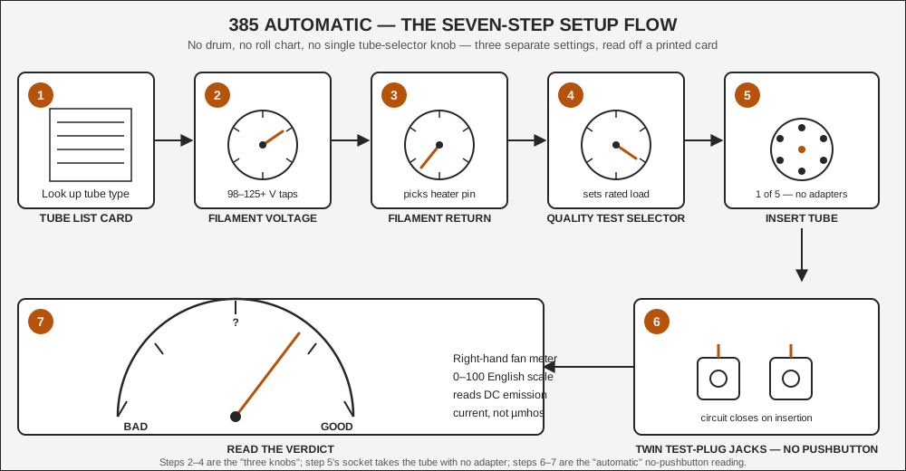
Step by step:
- Look up the tube type on the Tube List card (§2). Note the socket number and the three knob settings for that row.
- Set the Filament Voltage Selector to the tap the card specifies.
- Set the Filament Return Selector to the position the card specifies.
- Set the Quality Test Selector to the load value the card specifies.
- Insert the tube in the correct one of the five sockets — see §4 for how the socket choice works and why you can’t get it wrong by accident.
- Insert the twin test plugs into the circuit-breaking jacks. This is the “no pushbutton” part of “Automatic” — the circuit stays open until both plugs are seated, then closes on its own (§5).
- Read the right-hand meter: BAD — ? — GOOD (§7).
None of these seven steps are optional and none of them are automatic in the sense of “the tester figures it out for you” — every one of them is an operator decision, informed by the printed card. That’s the trade the 1935 engineering made: a $77.95 instrument that needs a card and three knobs, instead of a several-hundred-dollar mutual-conductance rig with “about ten controls” per tube (Vol 1 §3, Vol 2 §2 quote the manual’s own cost argument for why they chose this route).
4.3.3 Why a wrong setting mostly can’t hurt the instrument
The manual is explicit that operator error at this stage was a design concern, and that the fix was mechanical/electrical rather than procedural:
“A tube … cannot be placed in the wrong tube-testing socket, nothing happens if the wrong button is depressed, and the tester cannot be harmed by an incorrect selector setting or by a ‘shorted’ tube.” — Supreme, 385 Automatic Quick-Facts
This matters for a working bench: you can make a setup mistake without cooking the meter. What a setup mistake does cost you is accuracy — a wrong Quality Test Selector setting gives you a GOOD/BAD verdict that isn’t testing the tube against its correct rated load, which is a silent failure mode (the meter will still swing somewhere and look like an answer) rather than a loud one. Double-check the card row against the tube’s markings before you trust the reading — see §8 for what a marginal or surprising verdict should make you do next.
4.4 Choosing the Socket — No Adapters
The 385 has five physical tube-test sockets on the panel: 4-pin, 5-pin, 6-pin, 7-pin, and an 8-pin socket built for the (then brand-new) octal metal tubes. There are no adapter shells to lose or mismatch — the Tube List card tells you which of the five sockets a given type uses, and you plug straight in.
Table 4 — 4. Choosing the Socket — No Adapters
| Socket | Pins | Era-typical tube families (general) |
|---|---|---|
| 4-pin | 4 | Older four-pin battery/AC tube bases (early triodes, rectifiers) |
| 5-pin | 5 | Five-pin screen-grid-era bases |
| 6-pin | 6 | Six-pin bases |
| 7-pin | 7 | Small-shell seven-pin bases |
| 8-pin (octal) | 8 | The new metal-shell octal tubes the 385 was built to catch early |
A top-cap terminal (“Tube Test Top Cap”) is also provided on the panel for tubes whose control grid comes out to a cap on top of the envelope rather than a base pin — common on many 1930s-era RF and output tubes.
4.4.1 The 45° geometry trick behind “no adapters”
The 8-pin socket’s contacts sit on a 45° circle. The new octal metal tubes used pin spacing that falls on multiples of that same 45°, and — usefully — so did a good number of the older lower-pin-count bases the 385 also had to serve. The practical result: a 7-, 6-, 5-, or 4-pin tube whose pins line up with a subset of that 45°-spaced ring can be dropped straight into the 8-contact socket, simply leaving the unused contacts blank, without a mechanical adapter shell. The manual leans on exactly this fact to bill the 385 as “probably the first tester to be announced for complete tests of all 8-pin tubes” while still handling everything older with one unified socket architecture rather than four completely separate mechanisms with their own wiring.
The five distinct physical sockets on the panel exist for the base types that don’t collapse neatly onto that geometry — the point isn’t that every tube goes in the same hole, it’s that no tube needs a loose adapter shell to reach the right hole. Combined with the Filament Return Selector’s ability to route the heater to whichever pin a given base uses (§3.1), one socket family can serve tube bases whose designers never coordinated with each other.
4.4.2 You can’t insert it wrong
Physically, a given tube’s base only fits the socket it was designed for (a 6-pin base doesn’t seat in a 4-pin socket), and the manual’s protection claim quoted in §3.3 covers the electrical side — an incorrect selector setting or even a shorted tube in the wrong-seeming configuration doesn’t damage the tester. The one thing that does rely on the operator getting it right is accuracy, not safety: seat the tube fully, in the socket the card specifies, before proceeding to §5.
4.5 Running the Quality (Emission) Test
With the three knobs set (§3) and the tube seated in its socket (§4), you’re ready to run the “Quality Test” itself — the 385’s own name for its bench emission test, and the reading that grades the tube GOOD or BAD.
4.5.1 What’s happening electrically
The tube is wired as a diode-connected emitter operating under approximately its rated load. DC current from the tester’s power supply flows cathode-to-plate(s) through the tube, in series with the fixed and Quality Test Selector resistors that setting established in §3. That current — not a gain figure, not a signal response, just the raw DC the cathode is able to pass under load — is what the meter reads.
“the direct current passed by the tube is measured by one of the meters … the current is limited by the tube and two resistors, one of which is variable.” — Supreme, 385 Automatic factory manual (Fig. 5 discussion)
Full circuit-level detail — the exact resistor network, the ~10%-of-total-circuit protection margin, the fan-meter’s 0–1 mA / 300 Ω movement behind the scale — is in Vol 2 §4–5 and Vol 3 §2; this volume covers the operating side.
4.5.2 The no-pushbutton current path
Once the tube is seated and the knobs are set, the last physical step is inserting the twin test plugs into the circuit-breaking jacks. These jacks are wired so the measuring circuit stays open — no current flows, nothing is “live” through the meter path — until both plugs are seated. Once they are, the circuit closes on its own and the meter responds. This is the second thing “Automatic” in the model name actually refers to:
“keep the circuit closed until two pin plugs are inserted … eliminating the necessity for push-button switches … thereby enabling automatic current measurements.” — Supreme, 385 Automatic factory manual
The manual’s “closed” and the gloss above’s “stays open” describe the same jacks from two different vantage points, not a contradiction: these are circuit-breaking jacks — a normally-made bypass path keeps the meter shunted and inert (that’s the loop the manual calls “closed”) until both plugs are seated and break it, which is what routes current through the meter path for the first time (the loop the gloss above calls “stays open” until then).
There is no test button to press and hold; there’s no button to release and re-press if you want a second reading. Pull a plug and reseat it, and the reading repeats.
4.5.3 Give the tube a moment
AC-heater tubes need a warm-up period before their cathode reaches operating temperature and the emission reading stabilizes — treat the first several seconds of any reading with some suspicion and let the meter settle before recording a verdict, particularly on directly-heated (battery-type) tubes that respond faster and indirectly-heated tubes that respond more slowly. The manual doesn’t specify an exact warm-up interval in the pages surveyed for this dive; use ordinary bench judgment (the meter needle stops drifting) rather than a fixed clock figure.
4.6 Reading GOOD / ? / BAD
The right-hand fan meter’s lower arc reads, left to right: BAD TUBE — ? — GOOD TUBE, over a 0–100 English-reading scale (not calibrated in µmhos, not calibrated in any unit at all — it’s a verdict scale, not a measurement scale).
Table 5 — 6. Reading GOOD / ? / BAD
| Needle position | Verdict | What it means operationally |
|---|---|---|
| Deep into the BAD zone | Tube fails | Cathode emission has fallen well below rated load current for this tube type — pull it |
| Solidly in the GOOD zone | Tube passes | Cathode still delivers full rated-load emission current — safe to return to service by this test’s own criterion (see §8 for what that criterion does and doesn’t cover) |
| In the ? zone | Marginal | The tube is passing measurably reduced current relative to a fresh sample of its type — see §8.2 for how to handle this before you make a call |
The manual states its own accuracy claim for this design plainly, in the context of the emission- vs-Gm tradeoff it argues at length (Vol 1 §3, Vol 2 §2):
“…the emission tester came into favor, because a well-designed emission tester is more accurate than a poorly-designed grid-shift tester … about all that can happen … is the depreciation of the emitting qualities of the cathode … so why not test a tube by measuring the emission current?” — Supreme, 385 Automatic factory manual, p. 8
and gives a specific number: roughly 90% accuracy for a well-designed emission tester like the 385, against “95% or more” for a full mutual-conductance instrument that would have cost several hundred dollars and taken about an hour to test a set of tubes in 1935. That trade-off — speed and cost against a real but bounded accuracy gap — is the whole reason the pairing with the Heathkit TT-1 in Jeff’s collection makes sense as a two-instrument bench; see §8 and Vol 6 for how to actually use both.
⚠ Danger — a “GOOD” verdict is not a green light to skip visual/mechanical inspection. The emission test says nothing about a cracked envelope, a loose element, a gassy tube (not a named 385 function — see §8.3), or physical damage. It only says the cathode still emits adequate current under load.
4.6.1 Reading the needle precisely
The GOOD/?/BAD arc is a wide zone, not a hairline pass/fail threshold — the manual’s own ~90% accuracy figure (above) is itself an acknowledgment that this is a coarser instrument than a calibrated Gm reading in µmhos. A few habits improve repeatability:
- Read at eye level, straight on to the meter face, not from an angle — parallax on a fan-shaped scale like this one is enough to shift a borderline needle position from “solid GOOD” to “high ?” depending on where your eye is relative to the glass.
- Compare against a tube of known-good condition of the same type, seated with the same three knob settings, whenever the verdict on an unknown tube looks surprising. A needle that lands in a noticeably different position than a known-good reference of the same type is more informative than the raw BAD/?/GOOD label alone.
- Record the actual needle position, not just the verdict word, if you’re keeping a service log for a set of tubes pulled from the same radio — “high GOOD, near the ? boundary” is a more useful note six months later than a bare “GOOD” when you’re deciding whether a marginal-sounding set is worth a full recap-and-retest pass.
4.7 The Neon Leakage & Short Test
Separately from the Quality (emission) reading, the 385 runs a distinct check for inter-element leakage, shorts, and opens inside the tube — a failure mode an emission current reading alone can miss entirely (a tube can emit plenty of current and still have a leaky element pair causing noise, hum, or distortion in a set).
4.7.1 How the test works electrically
The manual’s Fig. 6 shows the leakage-test circuit: 110 V AC in series with a neon glow lamp, a blocking capacitor C₁, and the tube-element pair under test. The blocking capacitor is the key design choice — it prevents a good tube (one with no leakage between the elements being checked) from rectifying the AC and lighting the neon lamp at all. If there is real leakage between that element pair, AC gets through, and both electrodes of the neon lamp glow — a visible, unambiguous pass/fail indication with no meter reading to interpret.
Quick-Facts item 24: “Indicates automatically elements between which leakage exists.”
The tube can be checked both cold and after it has been running hot in the socket for a while (Quick-Facts item 25 — “leakage while heated” — since some intermittent shorts only appear once elements have thermally expanded).
4.7.2 Why the lamp is deliberately desensitized
Supreme’s manual specifically calls out a design choice here, aimed squarely at a competitor marketing claim of the era:
The neon lamp is deliberately shunted to reduce its sensitivity, so that trivial or harmless leakage present even in good tubes doesn’t trip a false “leaky” indication — the manual explicitly criticizes competing testers that advertise being “twenty times more sensitive” as chasing a sensitivity that produces more false failures, not more useful information.
The practical upshot for you at the bench: if the neon glows on the 385’s leakage test, treat it as a real finding, not an oversensitive trip — the instrument was deliberately engineered to avoid crying wolf on this test.
4.7.3 What the surviving manual pages don’t spell out
The pages of the factory manual surveyed for this dive describe the circuit and the automatic, no-extra-button behavior of the leakage indication, but they don’t give a step-by-step “select element pair A, then B, then C” procedure independent of the tube-in-socket wiring already established for the Quality Test. Treat this as: the leakage check rides on the same socket connections you’ve already made for the emission test, and the neon’s automatic behavior (no pushbutton needed, per §5.2’s twin-jack mechanism) is what “automatically” in item 24 refers to, consistent with the rest of the “Automatic” naming logic in §3.3 and §5.2. If you need the exact per-pin sequencing for a specific tube base, that level of detail belongs with the schematic (Fig. 6) — see Vol 2 §4 and, if you have access to the full 13-page manual PDF, read Fig. 6’s caption directly rather than relying on a summarized account here.
4.7.4 Why this test earns its own place in the flow
It’s worth being explicit about why the 385 carries a second, independent test rather than folding leakage detection into the Quality Test’s single meter reading: a leaky or intermittently shorting element pair can sit alongside perfectly healthy cathode emission. A tube can pass the Quality Test solidly GOOD and still be the tube causing hum, motorboating, or intermittent distortion in a set, because the fault is a leakage path the DC emission current doesn’t reflect at all. Running both tests — emission current and neon leakage — on every tube, not just the ones that fail the Quality Test, is the closer-to-complete grading picture this instrument can offer within its 1935 design budget. Neither test alone is sufficient; together they cover considerably more ground than either does by itself, though neither reaches into transconductance territory (§8).
4.8 Interpreting Results — What Emission Catches, and What It Doesn’t
This is the section that actually matters for triage decisions on the bench, and it’s the section where the emission-vs-Gm framing that runs through this whole dive pays off in practical terms.
4.8.1 What a clean GOOD verdict tells you
A tube reading solidly GOOD on the 385’s Quality Test has demonstrated that its cathode still delivers approximately rated-load DC current. For a large share of tube failures — a tube that’s simply worn out, an emission-depleted cathode near end of life, a tube that’s gone stone dead — this is exactly the failure mode the test was built to catch, and it catches it well: per the manual’s own figure, roughly 90% accurate against a much more expensive reference method.
4.8.2 What a ”?” verdict tells you
A marginal reading means the tube’s emission current has fallen measurably below a fresh sample’s figure but hasn’t collapsed to a clear BAD. Treat ”?” as information, not as a coin flip to resolve arbitrarily:
- Re-test after a longer warm-up. A tube that reads ”?” cold and cleans up to solid GOOD after a proper warm soak may simply need more time to reach temperature.
- Cross-check against a second, fresh known-good tube of the same type in the same socket and settings, if one is available — this validates that the Quality Test Selector setting itself is correct for the type (a wrong card-reading or transcription error on your part will make every tube of that type look marginal or bad).
- Cross-check against the actual set the tube came from, where practical — a marginal emission tube that still performs acceptably in a low-demand circuit (a low-level audio stage, for instance) may be worth returning to service, while the same marginal reading in a stage that needs full rated output (a power output tube, an RF final) is a real candidate for replacement.
- If a Gm instrument is available, use it. This is precisely the scenario the Heathkit TT-1 pairing in Vol 6 exists for: a marginal emission reading doesn’t tell you why the tube is marginal, and a mutual-conductance reading can distinguish “still has usable gain, just slightly depleted cathode” from “gain has actually collapsed” in a way the 385 structurally cannot.
4.8.3 What the emission test does not catch — the central limitation
This is the fact this whole dive is built around, and it bears restating in plain operational terms: the Quality Test measures cathode emission current, full stop. It does not measure gain. A tube whose transconductance has degraded — reduced amplification, reduced ability to respond to a small grid signal with a proportional plate-current swing — can still pass enough raw DC current under a rated-load emission test to read solidly GOOD. The 385 has no way to see the difference between a tube that amplifies normally and a tube that amplifies weakly, as long as both still emit adequate current.
Table 6 — 8.3 What the emission test does not catch — the central limitation
| Failure mode | Does the 385’s Quality Test catch it? | Notes |
|---|---|---|
| Cathode emission genuinely depleted (worn-out tube) | Yes | The test’s actual design target — ~90% accurate per the manual |
| Dead short / open element | Yes — separately, via the neon leakage test (§7) | Not the same test as the Quality Test; run both |
| Reduced transconductance / gain, cathode still emitting | No | The central blind spot — this is the emission-vs-Gm gap; see Vol 1 §3, Vol 2 §2, Vol 6 |
| Microphonics | No | Not a DC current phenomenon; needs mechanical/acoustic testing, not covered by any 385 function |
| Some grid-current / gas conditions | Not directly | The manual does not name a distinct “gas test” function (§8.4) |
| Intermittent element leakage under heat | Partially | The neon test can be re-run hot (§7.1, item 25) but won’t catch every intermittent |
The manual makes this trade explicit rather than hiding it — it argues, correctly for a great many practical service scenarios, that most field tube failures are emission depletion, and that building a several-hundred-dollar, hour-per-set Gm rig to catch the smaller remaining slice of gain-only failures wasn’t the right cost/benefit call for a $77.95 service-bench instrument in 1935 (Vol 1 §3 quotes the manual’s cost argument in full). Whether that trade-off is the right one for a given tube, in a given circuit, in 2026, is exactly the judgment call §8.2’s cross-check guidance is meant to support.
4.8.4 “Gas test” — not a named function
If you’ve used other-era testers with a distinct “gas test” position, note for the record: the 385’s own manual does not name a separate “gas test” as a distinct labeled function. The tube grading on this instrument is the Quality (emission) Test plus the neon leakage/short/open check covered in §7 — that’s the complete grading picture this tester offers. Don’t go looking for a gas position on the panel; it isn’t there.
4.9 Using the VOM, Ohmmeter, and Capacitor Functions
The 385 is a combination instrument — beyond tube grading, the same two fan meters and shared circuitry double as a general-purpose volt-ohm-milliammeter and a capacitor tester, plus an in-circuit set analyzer (§10). This section covers the bench-meter functions; §10 covers testing a tube while it’s still sitting in a customer’s radio.
4.9.1 DC volts, AC volts, DC milliamps
Table 7 — 9.1 DC volts, AC volts, DC milliamps
| Function | Ranges | How it’s derived |
|---|---|---|
| DC volts | 0/5/25/125/250/500/1250 V | The 0–1 mA / 300 Ω meter movement plus voltage-multiplier resistors |
| AC volts / output | 0/5/25/125/250/500/1250 V | The same movement, fed through the copper-oxide instrument rectifier; the 5 V range uses a series capacitor as a reactive multiplier rather than a resistor, specifically to fight the copper-oxide rectifier’s nonlinear low-signal error (Vol 2 §5 covers why in circuit detail) |
| DC milliamps | 0/5/25/125/250/500/1250 mA | The same movement, switched to current shunts |
Both meters share the single 0–1 mA / 300 Ω basic movement design — the “uni-construction” approach the manual highlights lets two physical meters cover roughly thirty-two separate range combinations rather than needing a separate meter per function.
⚠ Danger — the rectifier protection is a pushbutton, and it needs to actually work. The copper-oxide rectifier is switched out of circuit except when the AC-volts or capacity ranges are active, and it’s shunted by a normally-closed pushbutton so surges bypass it until the operator deliberately opens the shunt to take a reading. If that pushbutton’s contacts are dirty or worn (a real risk on a 90-year-old instrument — see Vol 5’s contact-cleaning notes), the copper-oxide rectifier loses its surge protection. Verify this pushbutton makes clean contact as part of routine service, not just when something’s already gone wrong.
4.9.2 Resistance (ohmmeter)
The 385’s ohmmeter draws on two entirely separate internal power sources depending on range:
Table 8 — The 385's ohmmeter draws on two entirely separate internal power sources depending on range
| Range group | Power source | Coverage |
|---|---|---|
| Four low ranges | Self-contained flashlight battery (nominal ~1.5 V, with a 4.5 V battery referenced at the Fig. 10 zero-set) | Down to ¼ Ω lowest scale division; half-scale at 15 Ω on the 0/200 Ω range |
| Two high ranges | Miniature self-contained DC power pack, built around a small rectifier/triode tube (an 01A-class type, per the Fig. 9 schematic) with a ~350 V transformer winding and a ~4 mfd filter | 0/2 MΩ and 0/20 MΩ |
Combined, the six ranges span roughly 0.25 Ω to 20 MΩ.
Before trusting a reading: zero the ohmmeter using the electrical “Zero Adjuster” shown in the manual’s Fig. 10, every session, after the instrument has warmed up on its variac/isolation- transformer bring-up (§1). A battery that’s drifted low, or a copper-oxide rectifier that’s aged, throws the zero off in a way a fresh zero-set corrects for on the low ranges but can’t fully compensate on the high-MΩ ranges — see Vol 5 for the full recap/calibration sequence if zeroing alone doesn’t hold.
4.9.3 Capacitance
Table 9 — 9.3 Capacitance
| Test | Range / method | Reads |
|---|---|---|
| Electrostatic capacitors (mica, paper, ceramic — non-polarized) | Transformer taps feed a bridge-like network; leakage indicated via the same neon principle used for tube leakage (§7) | 0.001–12.5 mfd across 6 ranges; a glowing neon indicates a leaky capacitor even if its capacitance value looks nominal |
| Electrolytic capacitors | DC from the self-contained rectifier-tube power pack, through a current-limiting resistor | Condition read directly on the right-hand meter’s GOOD/BAD capacitor arc (the same meter face that reads tube GOOD/?/BAD, on a separate scale — §2.2) |
The capacitor tests share their DC supply with the high-range ohmmeter (the same rectifier-tube power pack), so the same warm-up and safety notes in §9.2 apply here too.
4.9.4 Reading discipline across all VOM functions
- Select the function/range before connecting test leads, not after — this is standard VOM discipline on any instrument of this era and protects both the meter movement and the rectifier/ battery paths from an unexpected overload during switching.
- Use the twin circuit-breaking jacks (§5.2) for current measurements, same as the tube test — the “no pushbutton” behavior applies to the milliamp ranges as much as it does to the Quality Test.
- Treat the copper-oxide rectifier’s condition as a live calibration variable. It ages and its forward resistance rises over decades, which throws off AC-volts accuracy specifically (not DC, not ohms) — if AC readings on a known-good source start drifting, suspect the rectifier before suspecting your technique. Vol 5 covers testing and, if necessary, sourcing a replacement (not selenium — see Vol 1 §5 and Vol 2 §5 for why that substitution is historically wrong for this instrument).
4.10 In-Circuit Testing — the Free Reference Point System
Beyond bench-socket tube grading and general VOM work, the 385 is also a set analyzer — it can test a tube (and take voltage/current readings) while the tube stays seated in a customer’s radio, using an analyzing cable that plugs into the radio’s own tube socket via what Supreme calls the “Free Reference Point System of Analysis.”
4.10.1 What it’s for
Pulling every tube out of a radio to bench-test it, one at a time, is slow and risks losing track of which tube came from which socket in a set with several identical types. An in-circuit analyzer lets you probe voltages, currents, and run a point test on a tube without removing it from the chassis, using the analyzing cable’s plug in place of the tube (or alongside it, depending on the specific point being checked) at the radio’s own socket.
The “Free Reference Point” naming reflects the general set-analyzer convention of the era: rather than requiring every measurement to be referenced against one fixed, hard-wired chassis point (which may be inconvenient or electrically noisy in a given set), the system lets the operator establish a convenient reference point in the chassis being serviced, rather than being locked to a single factory-designated test point.
4.10.2 The self-contained “grid-shift” battery — read this carefully
The in-circuit analyzer function draws on a self-contained “grid-shift” battery to run a point test on a tube while it’s in the set (Quick-Facts item 10: “Tube Testing from radio sockets with self-contained ‘grid-shift’ battery”).
Don’t let this function muddy the headline fact from §6 and §8. “Grid-shift” testing is the historical name for the mutual-conductance test method (Vol 1 §3, Vol 2 §2) — the very method the 385’s own manual spends two pages arguing against building as the instrument’s primary bench test. This in-circuit, battery-powered point check is a secondary, supplementary function for probing a tube inside a live chassis. The 385’s own-socket bench grading — the Quality Test covered in §5–§8 of this volume — remains an emission test. Don’t conflate the two: an in-circuit grid-shift point check and the bench emission Quality Test are different functions on the same panel, testing different things, with different accuracy characters.
4.10.3 Using it
- Connect the analyzing cable to the appropriate jack/plug arrangement on the 385’s panel.
- Insert the cable’s plug into the radio’s tube socket in place of (or alongside, per the specific point being checked) the tube under test.
- Establish your reference point per the Free Reference Point system’s operating convention for the set you’re servicing.
- Take the voltage/current readings, or run the grid-shift point check, per the specific fault you’re chasing in that set.
This dive treats the in-circuit analyzer as a documented capability rather than a step-by-step service procedure — the manual pages surveyed here (Quick-Facts items 7, 8, 10; Fig. 4) confirm the feature and its naming but don’t give a full worked example. If you’re actively troubleshooting a specific radio with this function, cross-check against the manual’s Fig. 4 directly.
4.11 A Worked Example: Grading a Pull of Tubes from a Radio
The individual steps in §3–§8 read cleanly in isolation; a bench session testing several tubes pulled from one radio is where the discipline of tracking card settings, sockets, and verdicts per tube actually gets exercised. This section walks a representative session end to end, using generic tube types to illustrate the workflow rather than asserting specific settings for any particular type (those come only from the Tube List card itself, per §2).
4.11.1 Before pulling anything
- Note the chassis layout first, if practical — a quick sketch or phone photo of which tube sits in which socket in the set, before you disturb anything. Several radios of this era used the same tube type in more than one socket (output stages in particular), and mixing up which physical tube came from which socket defeats the point of individually tracking results.
- Pull, seat, and grade tubes one at a time rather than pulling a whole set to the bench and sorting them out afterward — it’s slower per-tube but eliminates the single most common source of confusion in a multi-tube session: a mixed-up identity between two same-type tubes from different stages.
4.11.2 Per-tube flow, repeated for each tube in the set
Table 10 — 11.2 Per-tube flow, repeated for each tube in the set
| Action | |
|---|---|
| a | Read the tube’s type designation off its base or envelope |
| b | Find that type on the Tube List card; note socket #, Filament Voltage, Filament Return, Quality Test setting |
| c | Set the three knobs (§3) |
| d | Seat the tube in the specified socket (§4) |
| e | Insert the twin test plugs, wait for warm-up, read the Quality Test verdict (§5–§6) |
| f | Run the neon leakage test on the same tube before removing it (§7) |
| g | Record type, socket-of-origin, Quality Test verdict, and leakage result together — a running log per radio, not just per tube |
| h | Reset the three knobs before moving to the next tube — don’t assume the next tube in the set shares any of the previous tube’s settings |
4.11.3 What the resulting log tells you that a single verdict wouldn’t
A per-tube log across a whole set surfaces patterns a one-off reading can’t:
- A single tube reading ”?” while everything else in the set reads solid GOOD is a reasonable candidate for the fault that brought the radio to the bench in the first place — especially if it’s the type used in an output or detector stage, where marginal emission is more likely to be audible than in, say, a low-level IF stage.
- Every tube of the same type across a multi-tube set reading marginal together is a signal to suspect the setup, not the tubes — recheck the Tube List card row for that type against the actual knob settings you used; a transcription slip on the Quality Test Selector figure will make every tube of that type look uniformly worse than it actually is (§3.3).
- A tube that reads GOOD on the Quality Test but the set’s original complaint was weak or distorted audio is the textbook case for the emission-vs-Gm gap in §8.3 — this is exactly the situation where handing that specific tube to a mutual-conductance instrument (the Heathkit TT-1, per Vol 6) can resolve what the 385 alone cannot.
4.12 Common Operator Mistakes and How They Show Up
Most of what goes wrong at the panel isn’t a hardware fault — it’s a step skipped or transposed in the manual, three-knob setup this instrument requires. The following mistakes are worth recognizing by their symptom, since the 385 gives no error message beyond a meter reading that just doesn’t add up.
Table 11 — 12. Common Operator Mistakes and How They Show Up
| Mistake | What you’ll see | Fix |
|---|---|---|
| Wrong Filament Voltage tap (too low) | Tube reads BAD or weak ”?” even when known-good | Recheck the card’s voltage-tap column against the knob; under-heated cathode emits less current regardless of tube condition |
| Wrong Filament Voltage tap (too high) | Tube reads GOOD but may be running hotter than rated — repeated over-voltage sessions can shorten a good tube’s life | Recheck the tap; don’t rely on a “GOOD” verdict alone to confirm the tap is correct |
| Wrong Filament Return position | Tube may show no filament glow at all, or an erratic/zero reading, because the heater circuit isn’t actually completed through the pin the tube expects | Recheck against the card; confirm the tube’s base pinout matches the return position specified |
| Wrong Quality Test Selector setting | Meaningless GOOD or BAD verdict — the load resistance doesn’t match the tube’s rated load, so the current reading isn’t calibrated to anything real for that type | Recheck the card row; when in doubt, cross-check against a known-good sample of the same tube type at the same setting |
| Tube seated in the wrong socket for its base type | Physically won’t seat, or (for a lower-pin-count base dropped into the 8-pin socket per §4.1) seats but reads nothing useful if the pin mapping doesn’t actually match that tube’s base | Re-verify socket # against the card; confirm base-pin alignment, not just “does it physically fit” |
| Reading taken before warm-up settles | Inconsistent or drifting verdict between two readings of the same tube seconds apart | Wait for the needle to stop moving before recording a verdict (§5.3) |
| Ohmmeter or capacitor readings drifting session to session | Zero point wanders; readings on a known-reference component don’t repeat | Re-zero via the Fig. 10 Zero Adjuster every session (§9.2); if drift persists beyond a fresh zero, suspect battery or rectifier condition and move to Vol 5 |
| Rectifier-shunt pushbutton not making contact | AC-volts readings become erratic or the copper-oxide rectifier shows accelerated aging | Clean/verify the pushbutton contacts as part of routine service (§9.1, Vol 5) |
| Card row misread (adjacent tube type, similar name) | A confidently “GOOD” or “BAD” verdict that doesn’t match the tube’s actual condition, because the wrong row’s settings were used entirely | Double-check the exact type designation off the tube itself, character by character, against the card — many tube-type names in this era differ by a single letter or digit |
None of these mistakes damage the instrument (§3.3, §4.2) — the cost is entirely in a wrong or misleading verdict, which is why the cross-checking habits in §8.2 and §11.3 matter as much as the mechanical setup steps themselves.
4.13 Quick Reference — the Full Test Flow
Table 12 — 13. Quick Reference — the Full Test Flow
| Step | Action | Section |
|---|---|---|
| 0 | Bring the instrument up on variac + isolation transformer + series lamp; one-hand rule throughout | §1 |
| 1 | Look up the tube on the Tube List card: socket #, Filament Voltage, Filament Return, Quality Test setting | §2 |
| 2 | Set the Filament Voltage Selector | §3 |
| 3 | Set the Filament Return Selector | §3 |
| 4 | Set the Quality Test Selector | §3 |
| 5 | Insert the tube in the correct one of the five sockets (no adapter) | §4 |
| 6 | Insert the twin test plugs — circuit closes automatically | §5 |
| 7 | Let the tube warm up; read the right-hand meter: BAD — ? — GOOD | §6 |
| 8 | Run the neon leakage/short test (same socket connections) | §7 |
| 9 | Interpret a marginal ”?” — retest, cross-check, or hand off to a Gm instrument | §8 |
| — | (optional) In-circuit point test via the Free Reference Point analyzing cable | §10 |
| — | (optional) DC/AC volts, DC mA, ohms, capacitance via the VOM functions | §9 |
For the full history of why this instrument is an emission tester and not the transconductance design one collector reference mislabels it as, see Vol 1 §3 and Vol 2 §2. For the hardware behind every control named in this volume — the fan meters, the socket wiring, the selector shafts — see Vol 3. For bringing a stored or unknown-condition unit safely up to operating status before you ever reach this volume’s procedure, see Vol 5. For the condensed cheatsheet and the two-tester emission-vs-Gm bench workflow alongside the Heathkit TT-1, see Vol 6.
Sources
- Supreme Instruments — “The New Supreme Model ‘385 Automatic’ Tester” factory technical
manual / Radio Craft reprint, 13 pp. (front panel photo; Figs. 1–13 schematics; “385
Quick-Facts” back cover with meter-scale art and price):
https://stevenjohnson.com/supreme/data/supreme385-manual.pdf - Supreme Instruments archive downloads (385 Technical Manual, early Instructions & Tube Data
Sheet, “89 series and 385 Tube Data,” “1939 Updated Tube List”):
http://www.supremeinstruments.org/data.htm - Radiomuseum, “Automatic Tube Tester 385, Supreme Instruments” (1935 date, $77.95, Radio Craft
May 1935 ad, photo set):
https://www.radiomuseum.org/r/supreme_in_automatic_tube_tester_385.html - Supreme Instruments Corp. history:
http://www.supremeinstruments.org/history.htm - Steven Johnson, “Supreme Tube Testers and Radio Analyzers” (model summary table — note its
“385 = transconductance” entry contradicts the factory manual and is not relied on for this
volume):
https://stevenjohnson.com/supreme/tubetesters.htm - fourwater.com / MDB Ventures, Supreme 385 page (collector photos):
http://www.fourwater.com/equip/supreme/supreme.htm