Supreme Instruments 385 Automatic Tester · Volume 5
Supreme 385 Automatic — Vol 5: Refurbishing & Calibration
Ninety years of wax-paper caps, a copper-oxide rectifier that has quietly drifted, and a calibration procedure the factory manual wrote down for you — if you bring it up slowly and respect the parts that are secretly part of the metering network.
5.1 Before You Plug It In
A Supreme 385 that has been sitting in a basement or a barn since the Eisenhower administration is not a curiosity you power up to see what happens. It is a transformer-operated, mains-connected instrument built in 1935, with no polarized plug, no ground pin, a maze of original wax-paper and electrolytic capacitors, a copper-oxide rectifier that has been quietly aging since before most of its owners were born, and a small self-contained “power pack” running a rectifier tube at roughly 350 V. Treat it exactly like any other ~90-year-old piece of mains gear on the bench: assume nothing works safely until you have proven it does, one step at a time.
This volume covers refurbishing and calibrating the 385 as a bench project. Vol 3 §2–§4 covers the hardware you’ll be working on (meters, sockets, chassis layout) in more descriptive detail; Vol 2 covers the circuit theory behind the ranges you’ll be calibrating. Read this volume before touching a screwdriver to the case screws.
5.1.1 What kind of hazard this actually is
The 385’s line cord has two conductors, unpolarized, 1935-vintage. There is no assurance that “neutral” on the wall outlet corresponds to “neutral” inside the chassis — on a two-prong plug, it’s a coin flip which way it’s inserted, and nothing inside the tester cares. That means the chassis and portions of the front panel can float at full line potential relative to earth ground depending on how the cord happens to be plugged in. This is normal for the era and is exactly why isolation matters more here than it would on a modern grounded-and-fused instrument.
Inside, once the case is open, there are three voltage domains worth respecting:
- The 117 V primary side of the power transformer and the switched AC ranges (item: 1-A fuse in the primary, per the factory spec) — lethal in the ordinary household-wiring sense.
- A ~110 V AC feed dedicated to the neon leakage test (Vol 2 §4) — same lethality, easy to forget about because it doesn’t look like “the mains” once it’s routed to a small neon lamp and a blocking cap.
- A ~350 V winding feeding the power-pack rectifier tube (used for the two high ohms ranges and the capacitor-test DC supply) — lower current than the primary side, but 350 V DC across two damp fingers is still enough to hurt you badly, and the power-pack’s own ~4 µF filter cap can hold a charge after the unit is switched off.
⚠ Danger — This is a two-conductor, unpolarized, ungrounded 1935 instrument. With the case open, the chassis and portions of the panel can be at full line potential. Never work inside the case with it plugged directly into a wall outlet. Never assume a switched-off unit has bled down its own capacitors — verify with a meter before you put your hands near the power-pack section.
5.1.2 Bring it up on a leash, not straight into the wall
The correct order of operations, every time you power a freshly-acquired or long-dormant unit for the first time (and every time thereafter until you’ve fully requalified it):
- Inspect and replace the line cord if it shows any cracking, stiffness, or exposed conductor. Confirm the 1-A primary fuse is present, intact, and correctly rated — do not substitute a higher value “to stop it blowing.” A blown primary fuse the first time you power up is useful diagnostic information, not an obstacle to defeat.
- Never plug it directly into the wall for a first power-up. Route it through an isolation transformer (floats the chassis off the mains neutral — this is the single most important habit for ungrounded pre-war gear) feeding a variac (so you control the applied voltage rather than getting 0 V or 117 V with nothing in between) feeding a lamp limiter (a 60–100 W incandescent bulb in series with the hot leg — it glows dim under normal load and glows bright, current-limiting the fault, if there’s a short).
- Bring the variac up slowly from zero, watching the limiter lamp. A lamp that stays dim as you approach full voltage means the unit is drawing roughly normal current. A lamp that jumps to full brightness and stays there means a short somewhere downstream — stop, back the variac off, and go hunting before you proceed.
- Let electrolytics reform gradually near their working voltage rather than snapping straight to full line voltage on caps that have sat unpowered for decades. This is standard practice for any electrolytic-filtered vintage gear and is doubly relevant here because the power-pack filter cap has had ~90 years to dry out (§3.1).
- Keep one hand behind your back whenever you’re probing anywhere near the 110–350 V windings or the
AC ranges with the case open and the unit live. This is the same one-hand discipline documented for the
whole TestEquipment hub in
_shared/legal_ethics.md— it’s not optional theater, it’s the difference between current crossing one arm and current crossing your chest.
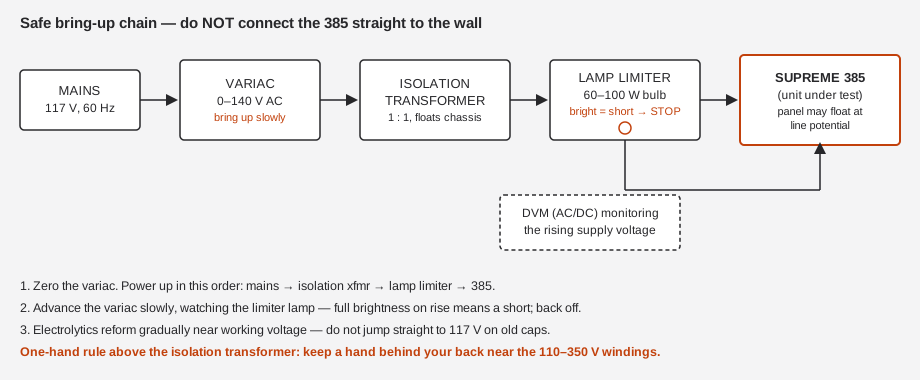
Once the unit survives a slow bring-up to full voltage without the limiter lamp flaring and without smoke, smell, or a tripped fuse, you can move on to the actual refurbishing work below — but do all of that work with the unit unplugged and verified de-energized; the bring-up procedure above is for testing, not for working inside the case.
⚠ Danger — The power-pack’s ~4 µF filter capacitor (§3.1) can retain a charge at up to ~350 V after the unit is switched off. Before opening the case to work, discharge it deliberately through a resistor (do not short it directly with a screwdriver) and verify near-zero volts with a meter before touching anything in that section.
5.1.3 Tools and materials before you start
Assemble everything below before opening the case. Nothing here is exotic, but running out of a consumable mid-teardown on a 90-year-old chassis — with wires unlabeled and half a selector wafer exposed — is how small jobs turn into multi-week ones.
Table 1 — 1.3 Tools and materials before you start
| Category | Item | Notes |
|---|---|---|
| Power/bring-up | Isolation transformer, 1:1, rated for the 385’s full load | §1.2 — non-negotiable for first power-up and for any live troubleshooting thereafter |
| Power/bring-up | Variac, 0–140 V AC | Pair with the isolation transformer; do not substitute a fixed-tap autotransformer |
| Power/bring-up | Lamp limiter (60–100 W incandescent bulb in a series-wired socket) | Cheap to build, essential; a dim-bulb tester is the same idea in a box |
| Reference standards | Bench DMM with a trusted-accurate AC and DC volts function | Used throughout §8; traceability doesn’t need to be metrology-lab grade, but it needs to be known accurate, not just “another meter” |
| Reference standards | A stable, known-accurate 5.00 V AC source | For the C1-adjust procedure, §8.2 — a bench AC calibrator, a known-good transformer tap verified against the DMM, or a signal generator into a buffer, whatever you have that you trust |
| Reference standards | A known-good tube of a common type, independently verified | For §8.5 — ideally cross-checked on the sibling TT-1’s Gm test as well as a separate reference emission tester if available |
| Capacitors | Modern film capacitors, assorted values matching the wax/paper parts you’ll find | Buy a modest assortment rather than one-offs; you will find more bad caps than you expect |
| Capacitors | Modern electrolytic(s) matching the power-pack filter spec, rated comfortably above the ~350 V winding | §3.1 |
| Cleaning | Contact cleaner rated safe for old wafer switches and pot/rheostat wipers (not a heavy degreaser or an abrasive spray) | §6 |
| Cleaning | Isopropyl alcohol (90%+) and lint-free wipes, for meter glass and general chassis grime | §5 |
| Cleaning | Small brass or nylon brush, soft | For wafer contacts — never steel wool or sandpaper on plated contacts |
| Hand tools | JIS/slotted screwdrivers sized for 1930s hardware, a set of insulated probes, a multimeter with a resistance function for continuity checks | General |
| Consumables | Fresh flashlight cell and 4.5 V battery, correct polarity noted before the old ones come out | §7 |
| Consumables | A discharge resistor (a few kΩ, adequate wattage) with insulated clip leads, for bleeding the power-pack filter cap before working near it | §1.1 danger callout |
| Documentation | A bench notebook or the log template in §10 | Write down every measurement before and after — see §9 |
5.2 Assessing the Patient
Before disassembling anything, do a visual-and-electrical triage. Most of what’s wrong with a 90-year-old Supreme 385 falls into a short list of well-understood failure modes, and knowing which ones you’re dealing with before you start pulling parts saves a lot of wasted motion.
5.2.1 A visual pass first
Before the unit is even powered up (via §1.2’s bring-up chain), open the case and look. This costs nothing and catches a surprising fraction of the problems below before you’ve spent any bench time chasing them electrically:
- Bulging, weeping, or cracked-can electrolytics — the power-pack filter (§3.1) is the obvious candidate, but check for any other electrolytic can that looks physically distressed.
- Wax/paper caps with visible wax bleed-out — a capacitor that has literally sweated its impregnating wax onto the chassis around it is long past reliable and should go on the replace list regardless of whether it tests bad on the bench (§3.2).
- Corrosion at the battery clips (§7) — often visible as a green or white crust, and often the first thing you’ll see when you open the battery compartment on a unit that’s been stored with an old cell still installed.
- Scorching, discoloration, or a burnt-plastic smell around any resistor or the power-pack tube socket — a sign of a prior overload event, which should make you suspicious of everything downstream of wherever the discoloration is worst.
- Broken, loose, or previously-repaired wiring — a 90-year-old instrument has usually seen at least one prior service pass, not always a competent one. Tack (repair) splices, non-original wire colors, or components that don’t match the manual’s Figs. 1–13 layout are all signs a earlier owner was in there before you, for better or worse.
- General case condition — case screws that are stripped or missing, a socket that’s visibly loose in its mounting, a selector knob that spins without engaging its wafer. None of these are safety issues by themselves, but each is a clue about how the unit was used and stored, which is useful context for everything that follows.
Log what you find in this pass (§9) before you touch anything — it’s your baseline, and it’s often the only record of what the unit looked like before your own work started changing it.
5.2.2 Then the table
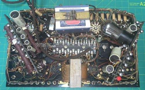
Use this table as a first-pass diagnostic map. It is organized as symptom → likely cause → what to actually do about it, cross-referenced to the section below that covers the fix in depth.
Table 2 — 2.2 Then the table
| Symptom | Likely cause | Fix | Detail |
|---|---|---|---|
| Meter reads full-scale or pegs immediately on power-up | Shorted or heavily leaky electrolytic in the power-pack filter; shorted wax/paper bypass cap | Isolate and replace the offending cap; verify with the lamp-limiter bring-up (§1.2) before re-testing | §3.1, §3.2 |
| AC-volts readings drift or read consistently high/low vs. a known reference | Aged copper-oxide rectifier (rising forward resistance); drifted C1–C6 multiplier network; a “helpful” prior owner swapped in a selenium stack | Verify/recalibrate the AC network; do not casually replace the rectifier type | §4.1, §4.3, §8.2 |
| Meter needle sticks, sluggish, or reads off-zero at rest | Dirty pivot/jewel, tarnished glass, mechanical zero drift | Clean movement, mechanically re-zero; electrically re-zero the ohms function after recap | §5 |
| Meter reads nothing at all, any function | Burned-open 0–1 mA movement (worst case) or an open shunt/multiplier in the selected range | Continuity-check the movement and its associated shunt network; a burned-open movement generally means sourcing a replacement fan meter | §5 |
| Good, known-working tubes read erratic BAD/?/GOOD on repeated tests | Dirty rotary-selector wafer contacts (Filament Volts, Filament Return, Quality Test) or dirty twin-jack contacts | Clean every wafer and jack contact; this is the single most common cause of “the tester lies” on an otherwise sound unit | §6 |
| Copper-oxide rectifier is unprotected / smells hot under AC/capacity ranges | Normally-closed rectifier-shunt pushbutton not making contact | Clean/verify the pushbutton; confirm it shunts the rectifier except when deliberately depressed | §6 |
| Low-ohms ranges or the in-circuit grid-shift point test are dead | Exhausted flashlight cell / 4.5 V battery, or corroded battery clips | Replace the battery; clean the clips | §7 |
| Tester “works” but you can’t set it up for a tube type you have | Missing or incomplete printed Tube List / Operating Data card | Source a reprint from the Supreme archive (supremeinstruments.org) | §7 |
| 5 V AC range reads off full-scale against a known 5.00 V reference | Drifted or substituted C1 (the reactive multiplier for that range) | Recalibrate per the C1 adjustment procedure — do not treat this as “close enough” | §3.3, §8.2 |
| High-ohms ranges (0/2/20 MΩ) dead or wildly wrong | Weak/dead power-pack rectifier tube, or its ~4 µF filter cap gone bad | Verify the tube (likely 01A-class, unconfirmed), verify/replace the filter cap | §3.1, §4.2 |
| Neon leakage test never glows, even on a known-shorted junk tube | Blocking capacitor C₁ (leakage-test path) open or the neon lamp itself dead | Verify the leakage-test C₁ and lamp separately from the AC-multiplier C1 — they are different components in different circuits despite sharing a reference designator across the manual’s figures | §2 note below, §3.3 |
A note on naming: the factory manual uses C₁ for two different components in two different figures — the blocking capacitor in the neon leakage-test circuit (Fig. 6) and the series reactive multiplier capacitor in the AC-voltmeter network (Figs. 1–3). They are not the same physical part and do not fail the same way. When you’re chasing a fault, confirm which C₁ the symptom actually implicates before you pull anything.
5.3 Recap — What to Replace, What to Match
“Recap” on most 1930s–1950s tube gear means one thing: replace every wax/paper and electrolytic capacitor on sight, because they are all past their design life and it’s cheaper to do it once than to chase intermittent faults for years. The 385 mostly follows that rule — but it has a wrinkle that a generic recap checklist will miss, and getting it wrong will leave you with a tester that powers up fine and lies to you on the AC-volts ranges forever.
5.3.1 The power-pack filter electrolytic
The self-contained power pack (Fig. 9 in the factory manual) runs a small rectifier tube feeding a ~4 µF filter capacitor that smooths the DC supply used for the two high-ohms ranges (0/2/20 MΩ) and the capacitor-test DC supply. This is exactly the kind of electrolytic that fails predictably on a ~90-year-old instrument: the electrolyte dries out, capacitance drops, ESR climbs, and the DC supply it’s supposed to filter starts riding on ripple.
- Symptom pattern: noisy/unstable high-ohms readings, a hum-modulated capacitor-test result, or (worst case) a shorted electrolytic that pulls the power-pack rectifier tube into an overcurrent condition on every power-up.
- What to do: reform it slowly on the variac if you want to preserve an original-can capacitor for display purposes, but for a unit that’s actually going back into service, replace it outright with a modern electrolytic of equivalent capacitance and a working-voltage rating that comfortably clears the power pack’s ~350 V winding. This one is not a calibration element in the sense C1 is (§3.3) — it’s a filter, and a reasonable modern substitute with the right µF and voltage rating does the job.
- Check for any other electrolytic in the capacity-reference or filter circuitry at the same time — the manual’s capacitor-test section (Fig. 8) reads electrolytic condition on the GOOD/BAD meter scale, which means the instrument’s own reference/filter electrolytics are subject to the identical aging mechanism as the customer capacitors it’s meant to be grading. Don’t let the fox guard the henhouse.
5.3.2 Wax/paper bypass and blocking caps — the ones that are just bypasses
Most of the small wax-and-paper capacitors scattered through the chassis (bypass caps, decoupling caps not in the metering signal path) are safe to replace on sight with modern film capacitors of the same nominal value. Wax/paper dielectric caps of this era leak DC, drift in value, and are a leading cause of erratic behavior on any tube-era instrument; there’s no argument for keeping them once you’re inside the case.
5.3.3 The caps that are secretly part of the metering network — do not casually swap
This is the part a generic “recap everything with whatever’s in the parts bin” pass will get wrong, and it’s worth stating plainly: not every capacitor in the 385 is just a bypass. Two groups are load-bearing calibration elements, and treating them like ordinary bypass caps will quietly wreck the instrument’s accuracy even though it will power up and “work” in every casual sense.
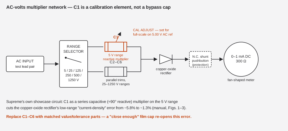
The AC-voltmeter multiplier network, C1–C6 (Figs. 1–3). Supreme’s own showcase circuit uses a series capacitor C1 as a reactive multiplier on the 5 V AC range instead of the resistor you’d expect, specifically to fight the copper-oxide rectifier’s nonlinear “current-density” error at low signal levels — the manual documents this cutting the 5 V-range error from roughly 5.8% down to about 1.3%. Parallel capacitors C2–C6 trim the higher ranges to the correct 1.11 RMS/average form-factor relationship. The 5 V AC range’s absolute accuracy is a direct, literal function of C1’s capacitance value. Swap in a “close enough” film cap of a different value or tolerance and you have re-opened exactly the error Supreme engineered C1 to close — the meter will still move, it will just be wrong, and it will look calibrated because nothing about a wrong reading on an unfamiliar 90-year-old meter face screams “wrong.”
The neon leakage-test blocking capacitor, C₁ (Fig. 6). This is the other C₁ (see the naming note at the end of §2) — a blocking cap in series with the neon glow lamp and the 110 V AC leakage-test feed. Its job is to prevent a merely-good tube from rectifying enough to light the neon on its own; get its value wrong and you either desensitize the leakage test to the point it misses real shorts, or oversensitize it to the point it flags harmless leakage in good tubes — precisely the “twenty-times-more-sensitive” overreach the manual explicitly criticizes competing testers for.
The rule for both: match value and tolerance to the original spec, not just “close enough.” If the original is out of tolerance or leaky, replace it with a modern film capacitor of the same rated value and the tightest tolerance you can reasonably source — do not substitute a nearest-standard-value part without recalculating what that substitution does to the range accuracy it participates in.
5.3.4 If you can’t read the value off the old part
The factory manual’s schematic pages (Figs. 1–3, 6) establish which capacitors are calibration elements and why — C1 as the 5 V-range reactive multiplier, the separate leakage-test C₁ as the blocking cap — but the scanned manual available to this research does not print fully legible numeric values for every one of them. That is a real gap, and it’s worth being honest about rather than inventing a number that sounds plausible. Two practical approaches, in order of preference:
- Read the value off the physical part before you pull it, if it’s still legible. Wax/paper caps of this era are printed or stamped with a value and often a tolerance band (color-coded, similar in spirit to resistor color codes but with era-specific conventions) — record it in your bench log (§9) before desoldering, even if the part is clearly bad. A leaky or drifted cap can still carry its original printed value even though its measured value has wandered.
- Measure the old part on a capacitance/ESR meter before assuming the printed value is trustworthy, and compare the two. A part that measures close to its printed value but shows high ESR or leakage is a candidate for a straight like-for-like replacement. A part that measures far from its printed value has likely drifted enough on its own to explain a calibration discrepancy even before age-related leakage became obvious — which is exactly the failure mode the AC-network warning in §3.3 is about.
If neither the part nor a service reprint gives you a trustworthy value, the fallback is empirical: replace with your best estimate of the original spec, then let the §8.2 C1-adjust procedure (which references a known 5.00 V AC standard, not the capacitor’s nameplate value) set the effective working point. That procedure exists precisely because component-level tolerances in a 90-year-old instrument were never going to hold to a modern lab standard on their own — the adjustment is how Supreme’s own techs handled exactly this problem at the factory.
5.3.5 Recap reference table
Table 3 — 3.5 Recap reference table
| Component | Where it lives | Original type (era-correct) | Typical failure mode | Replace or match? | Calibration impact if wrong |
|---|---|---|---|---|---|
| Power-pack filter cap (~4 µF) | Fig. 9, self-contained power pack | Wet or dry electrolytic can | Dried electrolyte → low capacitance, high ESR; sometimes shorts | Replace with modern electrolytic, correct µF and voltage rating | Ripple on high-ohms/cap-test DC supply; not a precision element |
| General bypass/decoupling caps | Scattered through chassis, not in the metering signal path | Wax/paper tubular | DC leakage, value drift, physical cracking | Replace freely with modern film | None — not in a calibrated range |
| C1 — AC-volts 5 V range multiplier | Figs. 1–3, series with the 5 V range | Precision-ish film/paper, reactive multiplier | Value drift shifts the 5 V range calibration directly | Match value & tolerance, not nearest-standard | Direct — this is the C1-adjust calibration point (§8.2) |
| C2–C6 — AC-volts higher-range trims | Figs. 1–3, parallel trims | Film/paper | Value drift shifts form-factor correction on 25–1250 V ranges | Match value & tolerance | Moderate — affects higher AC-range accuracy |
| C₁ — neon leakage-test blocking cap | Fig. 6, in series with the neon lamp and tube under test | Paper/mica blocking cap | Leaky cap over-sensitizes the leakage test; open cap kills it entirely | Match value & tolerance | Direct — sets leakage-test sensitivity/threshold |
| Electrolytics in capacity-reference/filter circuits | Alongside Fig. 8 circuitry | Electrolytic | Same aging as any electrolytic of the era | Replace with modern equivalent | Affects electrolytic-capacitor-test accuracy (the instrument grading itself) |
5.4 The Rectifiers — What’s Actually In There, and Why You Shouldn’t “Upgrade” It
This is the single most consequential correction to make before doing any refurbishing work on a 385: it does not contain a selenium rectifier. Selenium rectifiers are a late-1930s/1940s technology and would be anachronistic in a 1935 design. What the 385 actually has is two separate rectification stages doing two separate jobs, and conflating them — or “helpfully” replacing either with something more modern without recalibrating — is how you end up with a tester that reads confidently wrong.
5.4.1 The copper-oxide instrument rectifier (AC-voltmeter path)
The AC-voltmeter/output function runs through a copper-oxide instrument rectifier feeding the 0–1 mA meter movement. Copper-oxide rectifiers age by rising forward resistance — as the junction degrades over decades, less of the applied AC actually gets through to deflect the meter for a given input voltage, which throws off AC-volts calibration in a direction that reads low relative to a fresh unit, all else equal.
- Test it against a known-good AC reference before assuming the rest of the AC network is at fault for a calibration discrepancy — see §8.2 for the procedure. Practically: apply a known AC voltage on a mid-range setting and compare the meter’s reading against your bench DMM’s AC-volts reading on the same input. A rectifier with elevated forward resistance will show a low reading that gets proportionally worse at lower input voltages (because the rectifier’s forward drop becomes a larger fraction of the smaller signal) — that voltage-dependent error signature is the tell that distinguishes a tired rectifier from a simple multiplier-network drift, which tends to produce a more uniform percentage error across the range.
- Visual inspection can also tell you something. A copper-oxide rectifier stack that shows corrosion, discoloration consistent with heat, or physical damage to the washers/plates is a candidate for replacement on sight, independent of the electrical test above.
- Sourcing a replacement copper-oxide rectifier is genuinely hard. These parts have not been in production for decades — copper-oxide instrument rectifiers were largely superseded first by selenium in the late 1930s–40s and then by silicon from the 1950s onward — and NOS stock is thin. Budget real time for this if the original tests bad; it is likely to be the single hardest part on this entire refurbishing list to source, harder than the meter movement and harder than the power-pack tube.
- Do not substitute a silicon diode or a selenium stack “because it’s close enough.” The entire AC multiplier network (C1–C6, §3.3) was trimmed at the factory to this rectifier’s forward-voltage and current-density curve. A silicon diode has a fundamentally different forward-conduction characteristic (lower, more constant forward drop vs. copper-oxide’s more current-dependent behavior) — swap the rectifier type and every range on the AC-volts function needs to be recalibrated from scratch against the new device’s curve, not just the range you think you’re fixing. If you do end up making this substitution out of necessity, document it explicitly in the unit’s service record (§9) — a future servicer (possibly you, years later) needs to know the instrument no longer matches its factory schematic before they trust any of the AC-volts figures at face value.
5.4.2 The power-pack rectifier tube
The self-contained power pack (Fig. 9) runs a small rectifier/triode tube — the manual’s Fig. 9 artwork reads as an 01A-class triode, though the type is not spelled out in plain text on the scan available to this research, so treat the exact type designation as a likely-but-not-fully-confirmed identification. This tube, along with its ~4 µF filter cap (§3.1), supplies the DC for the two high-ohms ranges (0/2/20 MΩ) and the capacitor-test function.
- Verify it in a known-good tube tester (ironically, the sibling Heathkit TT-1 — see Vol 6 — is a fine tool for checking this specific tube’s emission/Gm before it goes back into the 385’s power pack, and doing so is a small, self-contained demonstration of the emission-vs-Gm theme that runs through this whole pair of instruments: you’d be using a dynamic Gm tester to qualify a tube destined for service inside an emission tester).
- A weak power-pack tube will show up as sluggish or low-reading high-ohms ranges and a soft capacitor-test DC supply; substitute a known-good equivalent if the original tests marginal.
- Because the exact type designation is a likely-but-unconfirmed reading of the manual’s Fig. 9 artwork (§ above), don’t assume a replacement tube needs to be an exact factory-original part number. What matters is that the substitute is electrically equivalent for this application — a small rectifier/triode capable of the power pack’s modest current demand at its ~350 V winding — not that it carries an identical stamp. If you pull the original for inspection, photograph and record its visible markings (§9) before assuming any particular type number; that photographic record is more trustworthy than a secondhand reading of a scanned schematic drawing.
- The power pack is a small, largely self-contained sub-assembly (Fig. 9) — it’s worth treating as its own mini-project within the larger refurb: verify its transformer winding, its rectifier tube, and its filter cap (§3.1) together, and confirm its output DC voltage independently before wiring it back into the ohms and capacitor-test functions it feeds.
5.4.3 Why the “just use silicon” shortcut is worse than it looks
It’s tempting, once you’re inside the chassis anyway, to replace the copper-oxide rectifier with a small silicon diode and call it an improvement — modern parts are cheap, reliable, and don’t age the way copper-oxide does. Resist this on a unit you intend to use as a calibrated instrument. The 385’s AC-volts accuracy is not “rectifier plus meter” in isolation; it is rectifier curve plus the C1–C6 network that was specifically shaped to compensate for that curve’s nonlinearity (§3.3). Change the rectifier and you change the error the network was built to cancel, at every range, simultaneously. If you do replace it — because a good copper-oxide part genuinely cannot be sourced — treat the entire AC-volts function as needing full recalibration from a voltage reference, not just a spot-check of the range you were originally chasing.
5.4.4 Rectifier summary
Table 4 — 4.4 Rectifier summary
| Stage | Type | Feeds | Ages by | Replacement guidance |
|---|---|---|---|---|
| AC-voltmeter rectifier | Copper-oxide instrument rectifier | Meter movement, AC-volts/output ranges | Rising forward resistance → low-reading AC volts, worse at low input | Keep original if it tests within tolerance; if replacement is unavoidable, recalibrate the entire AC-volts function, not one range |
| Power-pack rectifier | Rectifier/triode tube, likely 01A-class (unconfirmed exact type) | High-ohms ranges (0/2/20 MΩ), capacitor-test DC supply | Normal tube emission decay over decades of intermittent use | Verify emission/Gm on a separate tester before reinstalling; substitute an electrically-equivalent tube if weak |
5.5 The Two Fan Meters
Both meters share a single basic movement design — 0–1 mA DC, 300 Ω — with the panel’s characteristic 5-inch fan shape achieved by “uni-construction” multiplexing of shunts and multipliers rather than by two different movements. That commonality is good news for service: whatever you learn cleaning and re-zeroing one applies to the other. Recall from Vol 3 §2 which meter carries which scale set: the left meter carries the OHMS/VOLTS/MILLIAMPERES/MFDS analyzer-and-VOM arc, while the right meter carries the GOOD-CAPACITOR/BAD-CAPACITOR arc and the BAD-TUBE/?/GOOD-TUBE emission-verdict arc — so a fault on the right meter specifically compromises the Quality-Test verdict that’s the whole reason this instrument exists.
5.5.1 Cleaning and mechanical re-zero
- Remove the meter face glass carefully (it’s original and likely irreplaceable in the exact fan profile — treat it gently) and clean both sides with isopropyl alcohol and a lint-free wipe; decades of case dust and off-gassing from old wax capacitors leave a haze that’s easy to mistake for a faded scale print rather than surface grime.
- Inspect the scale card itself while the glass is off — check for foxing, fading, or ink that’s lifting, and photograph it at high resolution before doing anything else. If the card is deteriorating, that photograph may end up being the only legible record of the exact scale artwork.
- Check for a sticking needle — gently tap the case and watch for a needle that doesn’t return smoothly to rest, or that lags visibly on a slow deflection. A d’Arsonval movement this age can have a dry or dirty jewel bearing; this is a job for someone experienced with delicate meter movements, not a general bench tinkerer, if it needs disassembly beyond the face glass.
- Mechanically re-zero each meter using the small zero-adjust screw on the face, standard practice for any analog movement, once you’re confident the needle is moving freely and isn’t fouled on the scale card or bent against a stop pin.
5.5.2 Electrical zero (ohms function)
Fig. 10 in the factory manual shows an electrical “Zero Adjuster” specifically for the ohms function. Set this after the recap work (§3) is complete and the battery (§7) is fresh — an ohms-zero set against a weak battery or a not-yet-recapped supply will drift again the moment you fix those other things, and you’ll end up chasing a “new” zero problem that’s actually just the old one resurfacing on a different component.
5.5.3 Worst case — a burned-open movement
If a meter reads nothing on any function, on any range, the movement’s coil may be burned open. This can happen from a shorted tube overloading the emission-test circuit, though the manual notes the Quality-Test selector is designed so the external circuit resistance is roughly 10% of total circuit resistance including a normal tube — meaning even a dead-shorted tube should only impose about a 10× overload, which “both meters fully protected” implies the design intends to survive. A genuinely burned-open coil despite that protection means sourcing a replacement fan-shaped movement, which is a much harder parts hunt than a capacitor or a common tube — budget accordingly, and rule out a simpler open (a broken lead, an open shunt resistor in the selected range) with a continuity check before concluding the movement itself is dead.
Before condemning a movement outright, work the fault down systematically:
Table 5 — Before condemning a movement outright, work the fault down systematically
| Check | How | If it passes | If it fails |
|---|---|---|---|
| Continuity of the movement coil itself | Ohmmeter (an external one — not the unit’s own, since that’s the thing under test) across the movement terminals, unit powered down and isolated | Coil is intact; fault is elsewhere in the range’s shunt/multiplier network | Movement coil is open; sourcing a replacement is the only path |
| Continuity of the selected range’s shunt/multiplier | Ohmmeter across the relevant component per Figs. 1–3/11–12, with the selector on the affected range | Component intact; check the selector wafer contact for that range (§6) | Open shunt/multiplier resistor — replace it, matching value on any range that participates in a calibrated function |
| Selector wafer contact for the affected range | Visual + ohmmeter continuity through the switch in that position | Contact good; problem is upstream (fuse, wiring) | Dirty/worn contact — clean per §6 before assuming a component fault |
5.6 The Maze of Contacts — Selectors, Twin Jacks, and the Shunt Pushbutton
The 385 has no rotating drum and no single tube-selection knob (Vol 3 §1 covers why the “Automatic” name is marketing rather than mechanism). What it has instead is a genuine maze of manual controls: the Filament Voltage Selector, the Filament Return Selector, the Quality-Test Selector, the various range selectors for the analyzer/VOM functions, the circuit-breaking twin jacks that give automatic current measurement without pushbuttons, and the normally-closed rectifier-shunt pushbutton protecting the copper-oxide rectifier.
Every one of these is a mechanical contact that has had ~90 years to accumulate tarnish, oxidation, and dust. Dirty contacts are the number-one cause of erratic or falsely-”BAD” readings on an otherwise sound unit — more common by far than an actually failed component, and the first thing to suspect (after verifying the tube itself, and after confirming the Tube List settings were entered correctly, per Vol 4) when a tube that should read GOOD reads ? or BAD inconsistently across repeated tests.
What to clean, systematically:
- Every rotary selector wafer — Filament Volts, Filament Return, Quality Test, and the analyzer/VOM range switches. Use a contact cleaner appropriate for old wafer switches (not an abrasive that will scratch the silver-plated or brass contact fingers), and exercise each switch through its full rotation repeatedly after applying cleaner to wipe contamination off the wiping surfaces.
- The circuit-breaking twin jacks. These are the mechanism that lets the 385 make “automatic current measurements” without pushbuttons — the circuit stays open until two pin plugs are inserted. Corroded or bent jack contacts will give intermittent readings on the analyzer/VOM functions that look exactly like a component fault. Clean and, if needed, gently re-tension the jack springs.
- The normally-closed rectifier-shunt pushbutton. This one deserves special attention because its failure mode is silent and consequential: it’s supposed to shunt the copper-oxide rectifier out of the circuit except when the operator deliberately depresses it to bring the rectifier into play for AC/ capacity ranges. If this contact is dirty or worn such that it doesn’t reliably close, the rectifier is unprotected — every power-up and every stray transient has a clear shot at a part that’s already hard to source (§4.1). Verify this one makes solid, low-resistance contact before you trust the unit with anything else.
- The five tube-test sockets themselves. Not a switch contact, but the same principle applies — 90 years of insertion cycles plus storage-time tarnish means the socket contacts deserve the same cleaning pass as the selectors. A dirty socket pin can produce exactly the same “intermittent BAD on a good tube” symptom as a dirty selector wafer, and it’s easy to overlook because it’s the last thing in the signal path rather than one of the obviously mechanical rotary controls.
5.6.1 Contact-point reference
Table 6 — 6.1 Contact-point reference
| Contact point | Function | Symptom if dirty/worn | Cleaning note |
|---|---|---|---|
| Filament Voltage Selector wafer | Sets filament transformer tap per tube type | Wrong or unstable filament voltage → erratic emission reading, possible tube stress from over/under-heating | Full-rotation exercise after cleaner application |
| Filament Return Selector wafer | Routes heater return to the correct socket pin | No filament continuity → tube reads dead/no current at all | Same as above |
| Quality-Test Selector wafer | Sets the per-tube emission-test load resistance | Reading drifts or won’t settle at the Tube List’s specified setting | Same as above; this one sees the most use-cycle wear |
| Analyzer/VOM range selector wafers | Selects DC volts / AC volts / DC mA / ohms / capacity ranges | Wrong-range or dead reading on the analyzer functions | Same as above |
| Circuit-breaking twin jacks | Completes the circuit for “automatic” (no-pushbutton) current measurement | Intermittent or dead analyzer-function readings that look like a component fault | Clean contacts, gently re-tension springs if sprung open |
| Normally-closed rectifier-shunt pushbutton | Protects the copper-oxide rectifier except when deliberately depressed | Rectifier unprotected — silent risk to a hard-to-source part | Verify solid low-resistance closed-contact reading before trusting the unit further |
| Five tube-test sockets (4-/5-/6-/7-/8-pin) | Physical tube connection for the Quality Test | Intermittent BAD on a known-good tube, isolated to one socket | Clean pins; check spring tension holds the tube’s pins firmly seated |
5.7 Consumables — Battery and the Tube List Card
Two non-electronic items are just as essential to a working 385 as anything covered above, and both are easy to overlook because neither one is “a repair” in the usual sense.
The battery. The low four ohms ranges and the in-circuit “grid-shift” point test run off a self-contained flashlight cell, with a 4.5 V battery referenced for the ohms Zero Adjuster set point (Fig. 10). This is exactly the “missing battery” collectors commonly mention when they pick up a 385 that’s been dormant — it has almost certainly leaked, corroded its clips, or simply gone dead over decades of storage. Replace it outright; do not attempt to nurse an original period battery back to life. Clean any corrosion off the battery clips before installing a fresh one — corroded clips will give you a weak or unstable low-ohms reading that looks like a battery problem even after the battery itself is fine.
The Tube List card. The 385 is, by design, useless for grading a tube it doesn’t have settings data for — the whole “Automatic” setup process (Vol 3 §1, Vol 4 §1) depends on looking the tube up on the printed “TUBE LIST” card to get the Filament Voltage, Filament Return, and Quality-Test knob settings. If your unit came without its card, or with only an early-issue card that predates your tube collection, this is a solvable problem: supremeinstruments.org hosts a downloadable archive including an early “Instructions & Tube Data Sheet,” an “89 series and 385 Tube Data” sheet (the Model 89/89-D bench tester shares the 385’s tube data), a “1939 Updated Tube List”, and the factory’s own 385 Technical Manual. Print whichever card matches your tube era — this is the closest thing the 385 has to a roll chart, and having it on hand is a prerequisite for using the tester at all, not just a nice-to-have.
5.8 Calibration Procedure
Once the recap (§3), rectifier verification (§4), meter service (§5), contact cleaning (§6), and consumables (§7) are done, calibrate the instrument in this order. Each step depends on the ones before it — don’t skip ahead, and don’t calibrate against a supply that hasn’t been brought up per §1.2 first.
5.8.1 Bring-up
Power the unit through the isolation transformer / variac / lamp limiter chain described in §1.2 and let it run for a few minutes at working voltage before calibrating anything — let the power-pack tube and the copper-oxide rectifier reach thermal equilibrium; calibrating a cold instrument and then using it warm (or vice versa) is a classic way to bake in an error you’ll chase for weeks.
5.8.2 The 5 V AC range — adjusting C1
This is the marquee calibration step, because it’s the one the factory manual documents explicitly and the one most likely to have drifted if C1 was ever “recapped” with a nearest-standard-value substitute (§3.3).
- Apply a known, accurate 5.00 V AC reference to the AC-volts input, on the 5 V range.
- Adjust C1 (the series reactive multiplier, §3.3, Figs. 1–3) until the meter reads exactly full-scale against that 5.00 V reference.
- Cross-check a couple of intermediate points if your reference source allows it (e.g., 2.5 V should read half-scale) — a single full-scale calibration point can mask a linearity problem elsewhere in the network that a two-point check would catch.
- If C1 has been replaced (§3.3/§3.4) rather than merely aged, expect to need a genuinely different adjustment position than “wherever it was” — don’t assume the pre-recap trim point is still valid once the part itself has changed.
5.8.3 DC volts vs. a reference
With the 5 V AC range trued up, verify the DC-volts ranges (0/5/25/125/250/500/1250 V) against a modern reference DMM or a known-accurate DC standard, one range at a time. Because the DC-volts function and the AC-volts function share the same 0–1 mA / 300 Ω meter movement but diverge into separate multiplier networks, a correct AC calibration does not guarantee correct DC calibration — verify both independently.
5.8.4 Ohms zero
With the battery fresh (§7) and the recap complete (§3), set the electrical Zero Adjuster (Fig. 10) on the ohms function. Do this last among the “reference-standard” steps, since it depends on battery condition and general circuit health more than on any single precision component — a fresh zero-set against a weak battery will drift again as soon as the battery sags further.
5.8.5 Spot-check the Quality-Test load against a known-good tube
Finally, verify the emission (Quality) test itself is behaving sensibly: run a known-good tube — ideally one whose condition you’ve already confirmed on a separate reference (ideally the Heathkit TT-1’s Gm test, completing the emission-vs-Gm loop this pair of instruments is built around) — through the 385’s own Quality-Test procedure per its Tube List settings, and confirm it reads solidly on the GOOD side of the scale. This isn’t a precision calibration step in the same sense as §8.2–§8.4 — there’s no adjustable trim specific to the emission test beyond the per-tube Quality-Test Selector setting itself — but it’s the final sanity check that the whole chain (filament supply, Quality-Test load resistor, meter, and the tube’s own actual condition) is behaving as a system before you trust the 385’s verdict on a tube of unknown history.
Remember what this spot-check can and can’t tell you: a known-good tube reading GOOD confirms the emission path is intact. It does not confirm the instrument would also flag a tube with collapsed transconductance but intact emission — no emission tester can, by design (Vol 1, Vol 2 §1). That’s the whole point of keeping the TT-1 on the same bench; see Vol 6 for the two-tester workflow this calibration work is ultimately in service of.
5.9 Common Mistakes Specific to This Tester
A generic “recap and calibrate an old tube tester” checklist gets most of the way there on a 385, but a few mistakes come up specifically because of how this particular instrument is built. Worth calling out explicitly, since each one produces a unit that looks fully serviced while quietly lying about something:
Table 7 — explicitly, since each one produces a unit that looks fully serviced while quietly lying about something
| Mistake | Why it happens | What it actually costs you |
|---|---|---|
| Assuming a selenium rectifier is inside because “that’s what old testers have” | Selenium was extremely common in slightly-later gear, and the assumption transfers without checking | You go hunting for a part that was never there, and risk misdiagnosing the actual copper-oxide rectifier as something else entirely (§4) |
| Recapping C1–C6 and the leakage-test C₁ with nearest-standard-value film caps, same as every other bypass cap in the chassis | They look like ordinary small capacitors sitting in a sea of ordinary small capacitors that all needed replacing anyway | Re-opens the exact AC-volts calibration error Supreme engineered C1 to close, or mis-sets the leakage-test sensitivity — and the unit will “work,” just wrong (§3.3) |
| Confusing the two C₁ reference designators (leakage-test blocking cap vs. AC-volts multiplier) when reading the manual’s figures | The factory manual reuses the label across Figs. 1–3 and Fig. 6 for two different physical parts | Fixing the wrong circuit while the actual fault (or the actual calibration-critical part) goes untouched |
| Treating the “Automatic” name as implying a rotating drum or single selector, and hunting for one during teardown | The marketing name plus familiarity with later roll-chart Supreme testers (the 500/503/504 series) sets an expectation this model doesn’t meet | Wasted teardown time looking for a mechanism that isn’t there, and confusion about how the three-knob setup (Vol 3 §1, Vol 4 §1) actually works |
| Swapping the copper-oxide rectifier for silicon and recalibrating only the range you happened to be chasing | Silicon diodes are cheap, available, and an obvious first instinct for “this old rectifier tests bad” | Every other AC-volts range is now off by an uncorrected amount, because the whole C1–C6 network was trimmed to the old rectifier’s curve (§4.3) |
| Setting the ohms Zero Adjuster before finishing the recap or before installing a fresh battery | It’s tempting to calibrate as you go, section by section, rather than waiting | The zero-set drifts again as soon as the deferred work (fresh battery, recapped supply) actually happens, and you end up doing it twice (§5.2, §8.4) |
| Skipping the known-good-tube spot-check (§8.5) because “the meters read fine on the bench reference voltages” | DC/AC-volts calibration and the emission (Quality) test are functionally separate systems that happen to share meter hardware | A unit can be beautifully calibrated on volts/ohms and still have a Quality-Test load fault that a volts-only calibration would never surface |
| Treating a good-tube-reads-GOOD spot-check as proof the tester “catches bad tubes” in the Gm sense | The framing this whole tester pair is built around (Vol 1, Vol 2 §1) is easy to forget mid-refurb, once the instrument is finally working again | Overconfidence in a tube grading that, by the emission method’s own nature, cannot see a collapsed-Gm/still-emitting tube — see §8.5’s closing note and Vol 6 |
5.10 Documenting the Work — A Bench Log Template
Every measurement in §8, every part replaced in §3–§7, and every visual finding in §2.1 is worth more a year
from now if it’s written down at the time, in the same units-cited, before/after style the rest of this
hub’s documentation uses (see the top-level TestEquipment/CLAUDE.md voice convention: “Cap C402 measured
0.18 µF / ESR 4.2 Ω against 0.22 µF / <1 Ω marked — replaced with WIMA MKS2,” not “the capacitor was bad
so I changed it.”). A simple table works well as a running log across multiple sessions:
Table 8 — so I changed it."). A simple table works well as a running log across multiple sessions
| Date | Section | Finding | Action | Result / measurement |
|---|---|---|---|---|
| e.g. 2026-XX-XX | §2.1 visual pass | Power-pack electrolytic can showing slight bulge at top | Flagged for §3.1 replacement, not yet pulled | — |
| e.g. 2026-XX-XX | §3.1 | Power-pack filter cap measured 1.1 µF / ESR >200 Ω against ~4 µF nameplate | Replaced with a modern 4.7 µF, 400 V electrolytic | New cap measures 4.6 µF / <1 Ω ESR |
| e.g. 2026-XX-XX | §4.1 | AC-volts 25 V range read 22.4 V against a 25.00 V reference before recap | Copper-oxide rectifier tested marginal; retained pending parts search | Documented pre-recap baseline for comparison |
| e.g. 2026-XX-XX | §8.2 | C1 adjusted against 5.00 V AC reference | Trimmer set to full-scale | Post-adjust: 5 V range now reads 5.01 V at 5.00 V input, 2.49 V at 2.50 V input (linearity check) |
Keep this log — or one shaped like it — in the unit’s own service record (Vol 3’s hardware notes are a reasonable home for a permanent copy once a refurb pass is complete), not just in a scratch notebook that might not survive to the next session.
5.11 A Working Log, Not a One-Time Project
Everything above is written as a first-pass refurbishing sequence for a unit coming out of long storage, but none of it — the recap, the rectifier check, the contact cleaning, the calibration — is a one-time event on an instrument this old. Copper-oxide rectifiers keep aging after you’ve verified them once. Wax/paper caps you didn’t get to on the first pass will keep failing on their own schedule. Contacts you cleaned will tarnish again over years of storage between uses. Treat this volume as a checklist to revisit periodically, not a box to check once and forget — and log what you find each time, using the template in §10.
Sources
- Supreme Instruments — “The New Supreme Model ‘385 Automatic’ Tester” factory technical manual /
Radio Craft reprint, 13 pp. (Figs. 1–13 circuit detail, including the copper-oxide rectifier network,
the power-pack rectifier tube, the C1–C6 AC-multiplier scheme, and the Zero Adjuster).
https://stevenjohnson.com/supreme/data/supreme385-manual.pdf - Supreme Instruments archive downloads (385 Technical Manual, early Instructions & Tube Data Sheet,
“89 series and 385 Tube Data,” “1939 Updated Tube List” — the printed Tube List card reprints referenced
in §7):
http://www.supremeinstruments.org/data.htm - Radiomuseum, “Automatic Tube Tester 385, Supreme Instruments” (photo set, dating, original price):
https://www.radiomuseum.org/r/supreme_in_automatic_tube_tester_385.html - Supreme Instruments Corp. history:
http://www.supremeinstruments.org/history.htm - EDN, “What’s It Worth: Supreme Instruments — Function Meets Art” (company/manufacturing background):
https://www.edn.com/whats-it-worth-supreme-instruments-function-meets-art/ - General era-appropriate antique-electronics service practice (isolation transformer / variac / lamp
limiter bring-up, electrolytic reforming, copper-oxide vs. selenium vs. silicon rectifier history) per
standard bench discipline for pre-war mains-powered instruments, cross-referenced against
_shared/legal_ethics.md.