Supreme Instruments 385 Automatic Tester · Volume 6
Supreme 385 Automatic — Vol 6: Cheatsheet & Emission vs Gm — the Two-Tester Bench
One page to grab before the tube goes in the socket, and the 1935-vs-1959 argument that explains why Jeff keeps two testers instead of one.
6.1 How To Use This Volume
This is the laminate. Everything below is pulled forward from Vol 1 through Vol 5 of this dive, condensed to tables you can read at arm’s length with a tube in one hand. If a row here disagrees with your memory of an earlier volume, the earlier volume is right — this page is a summary, not a new source. Every comparison row also carries a “detail” pointer back to the volume and section that explains the why.
The back half of this volume is the other reason the sheet exists: Jeff runs the 385 as one half of a deliberate pair with the Heathkit TT-1 (a true mutual-conductance tester, ~1959). §6 below lays the two methods side by side so the bench question — “which tester do I reach for, and what am I risking if I only use one” — has a one-glance answer.
6.2 Quick Specs — What This Unit Is
Table 1 — 1. Quick Specs — What This Unit Is
| Field | Value | Detail |
|---|---|---|
| Model | Supreme “385 Automatic” | Vol 1 §1 |
| Maker | Supreme Instruments Corp., Greenwood, Mississippi | Vol 1 §1 |
| Introduced | 1935 (Radio Craft, May 1935 back-cover ad); tube-data updates run to 1939 | Vol 1 §1 |
| Dealer net wholesale price | $77.95 (98–125 V, 60-cycle) | Vol 1 §1 |
| Test method (own-socket bench test) | EMISSION — “Quality Test.” NOT transconductance/Gm. | Vol 2 §1 |
| Meters | Two 5-inch fan-shaped d’Arsonval movements, 0–1 mA DC / 300 Ω each | Vol 3 §2 |
| Tube read-out | GOOD / ? / BAD, English-reading arc, 0–100 | Vol 2 §2 |
| Sockets | Five, no adapters: 4-, 5-, 6-, 7-pin, and 8-pin octal/metal (45° pin geometry) + top-cap terminal | Vol 3 §3 |
| Setup mechanism | Printed TUBE LIST card + three rotary knobs. No drum, no roll chart, no single selector knob. | Vol 3 §4, Vol 4 §1 |
| Rectifiers | Copper-oxide instrument rectifier (AC-volts path) + a rectifier tube (self-contained power pack, DC ohms/cap ranges). No selenium. | Vol 2 §3, Vol 3 §5 |
| Also does | Set analysis (Free Reference Point), full VOM (DC/AC volts, DC mA, ohms), capacitor tester (electrostatic + electrolytic), inter-element leakage/shorts via neon | Vol 1 §2, Vol 2 §4 |
| Case | Wood carrying case, bakelite front panel, ~18 in wide, ~22 lb | Vol 1 §1 |
| Mains | 98–125 V, 60-cycle; 1-A primary fuse | Vol 3 §5 |
“Automatic” is marketing, not a mechanism. It names three real features — a universal no-adapter socket set, circuit-breaking twin jacks that meter current without a pushbutton, and automatic neon leakage-element indication — not a rotating drum or a single tube-selection knob. See Vol 3 §4 for the full argument against the “rotary drum” reading of the name.
6.2.1 What This Unit Is NOT (kill the two most common misreadings)
Table 2 — 1.1 What This Unit Is NOT (kill the two most common misreadings)
| Myth | Reality | Detail |
|---|---|---|
| ”The 385 is a transconductance/Gm tester” (repeated on at least one respected collector summary table) | It is an emission tester. The factory manual spends two full pages (pp. 8–9) arguing against building a Gm tester on cost/complexity grounds and choosing emission instead. | Vol 2 §1 |
| “‘Automatic’ = rotating drum / roll chart / single selection knob” | Setup is manual: look the tube up on the printed TUBE LIST card, then set three separate rotary knobs (Filament Voltage, Filament Return, Quality Test) by hand. The roll chart is a later Supreme feature (500-series, late 1930s), not this unit. | Vol 3 §4 |
| ”It has a selenium rectifier” (era-appropriate guess, wrong here) | Selenium didn’t become common in US instrument gear until the late 1930s–1940s. This 1935 design uses copper-oxide + a rectifier tube. | Vol 2 §3 |
| ”It runs a gas test” | Not a named function in the factory manual. Grading is emission (Quality Test) plus a separate neon leakage/short/open test — those are pass/fail element checks, not a gas test. | Vol 2 §4 |
6.3 What the 385 Tests — Quick Menu
Table 3 — 2. What the 385 Tests — Quick Menu
| Test | What it actually does | Reads | Detail |
|---|---|---|---|
| Tube quality (emission) | DC current through the tube, diode-connected, under ~rated load; per-tube variable resistor set from the TUBE LIST card | GOOD / ? / BAD | Vol 2 §1–2, Vol 4 §2 |
| Inter-element leakage / shorts / opens | 110 V AC + neon glow lamp + blocking capacitor across an element pair; leakage lets AC through and lights both neon electrodes | Neon glow (which pair) | Vol 2 §4, Vol 4 §3 |
| Leakage while heated | Same neon test, tube hot | Neon glow | Vol 2 §4 |
| In-circuit set analysis | ”Free Reference Point” analyzing cable into a radio’s own tube socket; self-contained grid-shift battery for point tests on a tube in the set | Meter | Vol 1 §2 |
| DC volts | 0–1 mA movement + multipliers | 0/5/25/125/250/500/1250 V | Vol 2 §5 |
| AC volts / output | Copper-oxide rectifier + capacitive/resistive multipliers | 0/5/25/125/250/500/1250 V | Vol 2 §3 |
| DC milliamps | Meter + shunts | 0/5/25/125/250/500/1250 mA | Vol 2 §5 |
| Resistance | Flashlight battery (low 4 ranges) + miniature power pack w/ rectifier tube (high 2 ranges) | 0.25 Ω – 20 MΩ, 6 ranges | Vol 2 §5, Vol 3 §5 |
| Capacity | Transformer taps + neon (electrostatic leakage); electrolytic condition on GOOD/BAD scale | 0.001–12.5 mfd, 6 ranges | Vol 2 §4 |
The footnote that matters: item 10 of the factory Quick-Facts lists “tube testing from radio sockets with self-contained grid-shift battery” — that’s the in-circuit analyzer function, a different circuit path than the bench-socket test. Don’t let it muddy the headline: the 385’s own-socket bench grading is emission, full stop. Detail: Vol 2 §4.
6.4 Operating Quick-Steps — Card → Three Knobs → Socket → Read
The 385’s real operating sequence, laminate form. Full walkthrough with photos of each control in Vol 4.
Table 4 — 3. Operating Quick-Steps — Card → Three Knobs → Socket → Read
| Step | Action | Watch for | Detail |
|---|---|---|---|
| 1 | Look the tube up on the printed TUBE LIST card. Note filament voltage, filament return pin, and Quality-Test setting for this exact tube type. | Wrong-year card (pre-1939 cards miss later types); no card = tester is not usable for that tube | Vol 4 §1 |
| 2 | Set the Filament Voltage Selector (rotary, taps the multi-tapped filament transformer secondary) to the card’s value. | Don’t guess — wrong filament voltage cooks a good tube or gives a false reading | Vol 3 §4, Vol 4 §1 |
| 3 | Set the Filament Return Selector to the card’s pin. This is what lets one socket serve tubes with heater pins in different positions. | Easy to skip on a fast bench session — get it wrong and the tube won’t light at all | Vol 3 §4, Vol 4 §1 |
| 4 | Set the Quality Test Selector (the per-tube load resistor) to the card’s value. | This is the calibration-critical control — it sets rated load for this tube type | Vol 2 §5, Vol 4 §2 |
| 5 | Insert the tube in the correct one of five sockets (4-, 5-, 6-, 7-pin, or 8-pin octal) — no adapters. Use the top-cap clip if the tube has a grid cap. | A tube physically cannot go in the wrong socket; a shorted tube or wrong selector setting cannot harm the tester (the Quality-Test load resistor is engineered so external circuit resistance is ~10% of total, capping a dead short at roughly a 10× overload the meter is designed to survive) | Vol 2 §1, Vol 3 §3, Vol 4 §2 |
| 6 | Read the right-hand meter’s GOOD–?–BAD arc. | ”?” is a genuine doubtful zone, not a rounding artifact — treat as “retest / compare to a known-good sample” | Vol 2 §2, Vol 4 §4 |
| 7 | Run the neon leakage test (separate step) if you suspect inter-element shorts — the Quality Test alone does not check this. | Neon is deliberately de-sensitized; it will not flag trivial/harmless leakage in an otherwise good tube | Vol 2 §4, Vol 4 §3 |
Supreme’s own name for this: “Simple 3-step A.C. tube Tester” (their words, not a euphemism for the single-knob “Automatic” myth — three knobs, not three drum positions). Detail: Vol 3 §4.
6.5 Refurb Quick Order
Full teardown-and-recap procedure, part numbers, and the C1 calibration derivation are in Vol 5. This is the checklist to tape inside the lid.
Table 5 — 4. Refurb Quick Order
| # | Step | Why | Detail |
|---|---|---|---|
| 1 | Discharge / visual inspect before touching anything live. Check the line cord and the 1-A primary fuse are present and correctly rated. | 90-year-old cord insulation is not to be trusted; no polarized plug means the whole panel can float at line potential | Vol 5 §1 |
| 2 | Bring up power for the first time on a variac + isolation transformer + series lamp/current limiter, slowly. Never just plug it in. | Watches for shorts and reforms electrolytics gently instead of surging them | Vol 5 §1 |
| 3 | Reform or replace electrolytics — the ~4-mfd filter cap in the power pack (Fig. 9 circuit) and any electrolytic in the capacity-reference/filter paths. | Wet/dry electrolytics from the mid-1930s are the near-universal first failure | Vol 5 §2 |
| 4 | Recap the wax/paper caps — but match value and tolerance on the C1 calibration capacitor (the AC-volts range reactive multiplier) and its sibling caps C2–C6. Everything else can be modern film on sight-replace. | C1 sets the 5 V AC range accuracy directly — it is a metering component, not a bypass; swap it casually and the AC-volts function goes out of calibration | Vol 2 §3, Vol 5 §2 |
| 5 | Check the copper-oxide rectifier. These age and lose efficiency (rising forward resistance), which throws off AC-volts calibration. Test it; expect it to be hard to source a replacement. | The whole AC-voltmeter network was trimmed to this specific rectifier’s nonlinear curve — a selenium or silicon substitute needs full recalibration, not a drop-in swap | Vol 2 §3, Vol 5 §3 |
| 6 | Verify the rectifier/power-pack tube (Fig. 9’s triode, read as 01A-class); substitute an equivalent if weak. | Powers the DC high-ohms ranges and the capacitor-test DC supply | Vol 3 §5, Vol 5 §3 |
| 7 | Clean contacts — every rotary wafer (Filament Volts, Filament Return, Quality Test, range selectors), the circuit-breaking twin jacks, and confirm the normally-closed rectifier-shunt pushbutton actually makes contact. | Dirty contacts are the #1 cause of an erratic “BAD” reading on a genuinely good tube; an unmade shunt pushbutton leaves the copper-oxide rectifier unprotected on power-up | Vol 5 §4 |
| 8 | Replace the flashlight cell / 4.5 V battery (low-ohms ranges, grid-shift point test); clean corroded clips. | The “missing battery” collectors mention — cheap insurance | Vol 5 §4 |
| 9 | Re-zero both meters mechanically; use the electrical Zero Adjuster for the ohms function after recap. | Movements are 0–1 mA / 300 Ω — a burned-open movement is the worst-case failure, but a sticking or unzeroed needle is the common one | Vol 3 §2, Vol 5 §5 |
| 10 | Calibrate: adjust C1 for full-scale on a known 5 V AC input (the manual’s own stated procedure), verify DC volts against a reference, zero ohms via the Zero Adjuster, and spot-check the Quality-Test load against a known-good tube of a common type. | Closes the loop — proves the recap didn’t just replace parts but restored accuracy | Vol 5 §5 |
⚠ Danger — This is a mains-powered, transformer-isolated-nowhere 1935 chassis with a ~350 V winding feeding the power-pack rectifier tube and a 110 V AC leg feeding the neon leakage test. There is no polarized plug and no ground pin. Use the isolation transformer for every power-up, not just the first, keep one hand behind your back around the HV windings, and confirm the chassis is fully discharged (bleed the 4-mfd filter) before reaching in with a meter probe or screwdriver. Detail: Vol 5 §1.
6.6 Safety DON’Ts
Table 6 — 5. Safety DON'Ts
| Don’t | Because | Detail |
|---|---|---|
| Don’t plug it straight into the wall on a first power-up (or after any long storage). | No isolation, no polarized plug — the panel can sit at line potential; bring it up on a variac + isolation transformer + current limiter instead. | Vol 5 §1 |
| Don’t power on without confirming the 1-A primary fuse is present and correctly rated. | It’s the only overcurrent protection in the primary. | Vol 5 §1 |
| Don’t substitute a selenium or silicon rectifier stack for the copper-oxide unit without a full recalibration. | The AC-volts network (C1–C6) was trimmed to the copper-oxide part’s specific nonlinear curve, not a generic diode curve. | Vol 2 §3, Vol 5 §3 |
| Don’t swap the C1 calibration capacitor for an off-value substitute “because it’s just an old cap.” | It sets the 5 V AC range accuracy directly — the manual’s own calibration procedure is “adjust C1 for full-scale on a known 5 V input.” | Vol 2 §3, Vol 5 §2 |
| Don’t trust a “BAD” reading before cleaning contacts. | Dirty rotary wafers and jack contacts are the most common cause of a false-bad reading on this class of instrument. | Vol 5 §4 |
| Don’t treat the neon leakage test as a sensitive go/no-go for all leakage. | It’s deliberately de-sensitized so ordinary harmless leakage in a good tube doesn’t false-trip — Supreme explicitly criticized “twenty-times-more-sensitive” competitor claims as counterproductive. | Vol 2 §4 |
| Don’t grade a tube without the correct TUBE LIST card entry for that exact type. | Filament voltage, filament return pin, and Quality-Test load are all per-tube; guessing risks a bad reading or, on filament voltage, a cooked tube. | Vol 4 §1 |
| Don’t reach into the chassis without bleeding the power-pack filter cap and respecting the one-hand rule above ~50 V. | The power pack’s rectifier-tube winding runs to roughly 350 V; the neon leakage circuit runs a 110 V AC leg. | _shared/legal_ethics.md, Vol 5 §1 |
| Don’t assume “GOOD” on the Quality Test means the tube has healthy gain. | It only means the cathode still emits under rated load — see §6 below, this is the entire reason Jeff keeps a second tester. | Vol 2 §2 |
6.7 The Two-Tester Bench — Emission (385) vs Gm (TT-1)
6.7.1 Why the pair exists
The Supreme 385 (1935) and the Heathkit TT-1 (~1959) are not redundant — they measure different things about the same tube, and each catches a failure the other cannot. Jeff keeps both deliberately, and the 385’s own factory manual, written in 1935, is startlingly candid about why a cheaper emission design beats a Gm design for a service bench of that era:
“The emission tester came into favor, because a well-designed emission tester is more accurate than a poorly-designed grid-shift tester … about all that can happen [to an aging tube] … is the depreciation of the emitting qualities of the cathode … so why not test a tube by measuring the emission current?” — Supreme “385 Automatic” factory manual, p. 8
Supreme’s own cost argument against building a Gm tester: a true grid-shift instrument needs “batteries or a DC power pack … a control for each tube element … about ten controls [for a 7-element tube],” would “cost several hundred dollars, and require about an hour to test a set of tubes,” for a stated accuracy gain of roughly 90% (emission) versus “95% or more” (an expensive Gm set). That tradeoff is exactly the argument the Heathkit TT-1 answers 24 years later — Daystrom-era engineering and kit-building economics made a real grid-signal Gm instrument affordable for the home/service bench, using a Weston professional design (the 981-3) as the starting point.
6.7.2 Comparison Table
Table 7 — 6.2 Comparison Table
| Dimension | Supreme 385 (EMISSION) | Heathkit TT-1 (Gm) | Detail |
|---|---|---|---|
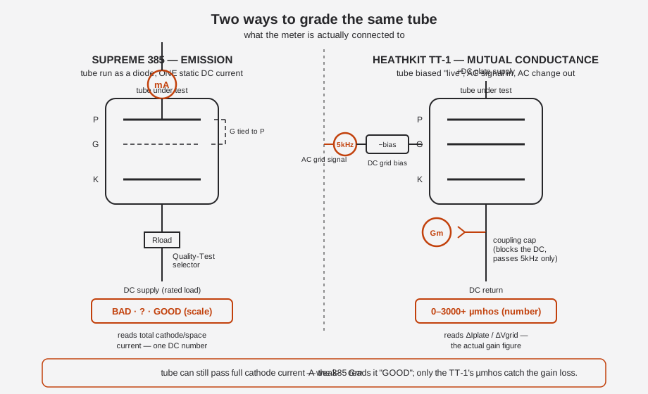
| What it actually measures | Total DC current the tube passes, diode-connected, under ~rated load | Transconductance: ΔI(plate) / ΔV(grid), via a 5 kHz AC signal injected on the grid at a realistic DC bias point | 385 Vol 2 §1–2 · TT-1 Vol 2 §2 |
| Read-out | GOOD / ? / BAD, English-reading arc | Direct numeric µmhos (0–3000 base scale, multipliers to ~24,000), compared against a minimum-Gm figure printed on the roll chart | 385 Vol 2 §2 · TT-1 Vol 2 §6 |
| What it catches | Cathode that has genuinely stopped emitting — the classic “weak/dead tube” | A cathode that still emits fine but has lost gain — the exact failure the 385 cannot see | 385 Vol 2 §2 · TT-1 Vol 2 §2 |
| What it MISSES | Any tube with collapsed transconductance that still passes adequate cathode current under the emission test’s load — it will read “GOOD.” | Full-power/full-dissipation behavior at the tube’s true operating point (Gm is measured at a fixed small-signal bench point, not under load); requires interpreting the number against a chart, not a pass/fail arc | 385 Vol 2 §2 · TT-1 Vol 2 §2 |
| Setup mechanism | Printed TUBE LIST card + 3 rotary knobs (Filament Voltage, Filament Return, Quality Test) | Illuminated roll chart + a bank of individual per-pin selector switches + P/G/K bus switches, set per the chart | 385 Vol 3 §4 · TT-1 Vol 2 §4 |
| Sockets | 5 sockets (4-/5-/6-/7-pin, 8-pin octal), no adapters | Built-in bank covering 4- through 9-pin miniature/octal/loctal + spares; a bolt-on TTA-1-1 adapter (making it a “TT-1A”) adds 12-pin Compactron + Nuvistor | 385 Vol 3 §3 · TT-1 Vol 2 §5 |
| Rectifiers | Copper-oxide (AC-volts) + a rectifier tube (power pack) | Silicon diodes (Heath CR-101) for the plate and bias DC supplies | 385 Vol 2 §3 · TT-1 Vol 2 §7 |
| Other built-in tests | Neon inter-element leakage/short/open, set analysis, full VOM, capacitor tester | Direct-reading leakage ohmmeter (0–10 MΩ), sensitive grid-current/gas test (¼ µA), life test (heater −10%), diode O.K./reject test, VR-tube regulation test | 385 Vol 2 §4 · TT-1 Vol 2 §3 |
| Complexity / control count | Low — 3 setup knobs + a socket choice | High — per-pin selector bank, P/G/K bus, PLATE/BIAS/SIGNAL/METER ranges, plus a self-contained CALIBRATE cycle | 385 Vol 3 §4 · TT-1 Vol 2 §4 |
| Approx. cost (period) | $77.95 dealer net wholesale, 1935 | Original kit price not confirmed in any period source found; a period catalog ad shows $134.50 — cite that only as a period catalog figure, not a confirmed original TT-1 kit price | 385 Vol 1 §1 · TT-1 Vol 1 §1 |
| Speed on the bench | Fast — card lookup, 3 knobs, socket, read | Slower — chart scroll, per-pin switch bank setup, bias/signal/plate range selection, then read and compare to chart minimum | 385 Vol 4 §1 · TT-1 Vol 2 §4 |
| Era | 1935 (in the field through ~1939) | Kit released circa 1959–1960; supported with tube-data supplements through 1978 | 385 Vol 1 §1 · TT-1 Vol 1 §1 |
| Lineage | House Supreme design; own emission “Quality Test” circuit | Kit-form redesign of the professional Weston 981 (Type 3 / 981-3), reworked into a Heathkit under common Daystrom ownership of Weston and Heath | 385 Vol 1 §2 · TT-1 Vol 1 §1 |
| Historical framing | The manufacturer’s own 1935 argument against building a Gm tester (cost/complexity, “several hundred dollars,” “about an hour to test a set of tubes”) | The answer to that argument, 24 years later, once grid-signal Gm circuitry could be kit-built affordably | 385 Vol 2 §1 · TT-1 Vol 1 §1 |
(See the diagram below for how the two circuits are actually wired differently around the same tube.)
6.7.3 The Failure Case, Spelled Out
This is the whole point of the pair, stated as a bench scenario:
- A tube’s cathode coating has partially depleted with age. Its transconductance has dropped well below a usable figure — it will sound weak, distorted, or gutless in the actual circuit.
- Because the cathode surface that remains is still active enough to pass rated-load DC current under the 385’s Quality Test, the meter needle swings into the GOOD arc. The 385 has no way to see the gain loss — it was never built to. (385 Vol 2 §2)
- The same tube on the TT-1: biased at a realistic operating point, the 5 kHz grid signal produces a reduced AC plate-current swing. The Gm meter reads a genuinely low µmhos figure — below the roll chart’s minimum-acceptable line for that type — and the tube is correctly rejected. (TT-1 Vol 2 §2)
The reverse gap exists too, in miniature: the TT-1’s Gm reading is a small-signal measurement at one bench operating point, not a full-power/full-dissipation test — a tube can look fine at TT-1 bias and still be marginal at its true full-signal operating current. Neither instrument alone is a complete verdict; the correct bench answer is emission first (fast triage — dead tubes get caught immediately and cheaply), Gm second on anything borderline or anything destined for a demanding circuit (audio output stages, RF front ends) where gain matters as much as “does it light up.”
6.7.4 When To Reach For Which
Table 8 — 6.4 When To Reach For Which
| Situation | Reach for | Why |
|---|---|---|
| Fast bulk triage of a box of pulled tubes | 385 (emission) | Three knobs, a socket, a read — this is what “Automatic” (the no-adapter socket + no-pushbutton metering) was built to speed up |
| A tube destined for an audio output stage or anything gain-critical | TT-1 (Gm) | Emission alone cannot certify gain; a weak-Gm tube reading “GOOD” on the 385 is exactly the failure mode the TT-1 exists to catch |
| A tube the 385 already flagged ”?” or “BAD” | Either — the 385’s verdict is already actionable | No need to escalate; emission failure is unambiguous |
| A tube the 385 passed “GOOD” but that sounds/performs weak in the actual set | TT-1 (Gm) | Confirms or overturns the emission verdict with an actual gain number against chart minimum |
| Suspected inter-element short or leakage | 385’s neon leakage test | The TT-1 has its own leakage ohmmeter (0–10 MΩ) and could also be used, but the 385’s neon test is faster to set up if it’s already on the bench |
| Suspected gas / grid emission | TT-1’s grid-current test (¼ µA sensitivity) | The 385 has no named gas-test function; this is a TT-1-only check on this bench |
| A rectifier or diode-type tube | Either — 385’s Quality Test and TT-1’s DIODES O.K./Reject zone both work | Both are emission-style checks for this tube class; Gm is not meaningful for a diode |
6.8 Common Bench Mistakes — Quick Diagnostic
Symptoms that show up as “the 385 is broken” that are usually something else entirely.
Table 9 — 7. Common Bench Mistakes — Quick Diagnostic
| Symptom | Likely cause | Fix | Detail |
|---|---|---|---|
| A known-good tube reads ”?” or “BAD” | Dirty rotary-wafer or jack contacts; wrong TUBE LIST card entry (superseded type not on an early card) | Clean contacts (§4 step 7); confirm the card revision covers the type — use the 1939 Updated Tube List for later types | Vol 4 §1, Vol 5 §4 |
| Tube won’t light in the socket at all | Filament Return Selector set to the wrong pin | Re-check the card entry for the correct return pin; this is the control most often set wrong under time pressure | Vol 3 §4, Vol 4 §1 |
| AC-volts function reads consistently off after a recap | C1 (or C2–C6) replaced with an off-value substitute instead of a matched part | Re-derive/verify C1 against the manual’s 5 V AC calibration procedure; don’t eyeball wax-cap replacements on this network | Vol 2 §3, Vol 5 §2 |
| Meter needle sits off zero with the tester powered down | Mechanical zero drift (movement handled/shipped) | Re-zero mechanically before assuming a fault; use the electrical Zero Adjuster for the ohms function separately | Vol 3 §2, Vol 5 §5 |
| Neon leakage test never lights, even on tubes you suspect are leaky | Working as designed — the neon is deliberately de-sensitized against nuisance trips | Don’t chase this as a fault; it’s a design choice Supreme explicitly defended against “more sensitive” competitor claims | Vol 2 §4 |
| 385 says “GOOD” but the tube performs poorly in the actual radio | Not a 385 fault — this is the emission-test blind spot | Cross-check on the TT-1 for a real Gm number; see §6.3 | Vol 2 §2, this vol §6 |
| Copper-oxide rectifier tested but AC-volts still drifts | Rectifier aging (rising forward resistance) faster than expected, or a mismatched substitute part installed at some point in the unit’s history | Confirm it really is the original copper-oxide type before recalibrating around it; a prior owner’s undocumented selenium/silicon swap will fight every future calibration attempt | Vol 2 §3, Vol 5 §3 |
6.9 Related Reading On This Bench
Table 10 — 8. Related Reading On This Bench
| Instrument | Role | Link |
|---|---|---|
| Heathkit TT-1 | The Gm half of this pair — full 6-volume dive | ../../../Heathkit TT-1 Tube Tester/02-inputs/volume_sources/vol1.md |
| Curve Tracers — Overview & Primer | The step beyond Gm: full I-V curve behavior, not just a single figure of merit | ../../../Curve Tracers Overview/CLAUDE.md |
| eTracer / uTracer6 | DIY pulsed-HV curve tracers — the “what does the whole plate curve look like” answer neither the 385 nor the TT-1 gives | ../../../eTracer/CLAUDE.md, ../../../uTracer6/CLAUDE.md |
_shared/comparison.md | Hub-wide cross-instrument decision matrix (where the 385 and TT-1 sit relative to everything else on the bench) | ../../../_shared/comparison.md |
_shared/legal_ethics.md | Mains/HV bench-safety discipline referenced throughout §4–§5 | ../../../_shared/legal_ethics.md |
The full triage spectrum on this bench, cheapest/fastest to most complete: 385 emission triage → TT-1 Gm confirmation → eTracer/uTracer6 full curve trace if a tube needs to be characterized rather than just graded. Most tubes never need to leave the first stage.
Sources
- Supreme Instruments, “The New Supreme Model ‘385 Automatic’ Tester” — factory technical manual /
Radio Craft reprint, 13 pp. (front-panel photo; Figs. 1–13 schematics; “385 Quick-Facts” back cover):
https://stevenjohnson.com/supreme/data/supreme385-manual.pdf - Supreme Instruments archive downloads (385 Technical Manual, “89 series and 385 Tube Data,” 1939 Updated
Tube List):
http://www.supremeinstruments.org/data.htm - Radiomuseum, “Automatic Tube Tester 385, Supreme Instruments”:
https://www.radiomuseum.org/r/supreme_in_automatic_tube_tester_385.html - Supreme Instruments Corp. company history:
http://www.supremeinstruments.org/history.htm - Steven Johnson, “Supreme Tube Testers and Radio Analyzers” (model summary table — note its “385 =
transconductance” entry contradicts the factory manual and should not be relied on):
https://stevenjohnson.com/supreme/tubetesters.htm - EDN, “What’s It Worth: Supreme Instruments — Function Meets Art”:
https://www.edn.com/whats-it-worth-supreme-instruments-function-meets-art/ - WorthPoint listing, “Supreme 385 Automatic Tube Tester with Original Manual – 1939”:
https://www.worthpoint.com/worthopedia/supreme-385-automatic-219583399 - Heathkit TT-1 Operation/Assembly manual (OCR), rsp-italy.it mirror:
https://www.rsp-italy.it/Electronics/Kits/_contents/Heathkit/Kits/Heathkit%20TT-1%20Tube%20tester%20Manual.pdf - Kent Nickerson, “Refurbishment and Verification of the Heathkit TT-1 Tube Tester” (hands-on primary
refurb report):
https://paulcarbone.com/blog/wp-content/uploads/2020/06/TT1_Refurbishment.pdf - Heathkit Virtual Museum, TT-1:
https://heathkit-museum.com/test/hkTT-1.html - RadioMuseum, “Heath Tube Tester TT-1”:
https://www.radiomuseum.org/r/heath_tube_tester_tt_1_tt.html - Alan Douglas, Tube Testers and Classic Electronic Test Gear (ISBN 1886606145).
- Weston lineage:
http://www.vacuumtubes.com/981.htmlandhttps://vintagetubeelectronics.com/weston-981-type-3-tube-tester/