uTracer NXT · Volume 1
uTracer NXT — Vol 1: What It Is & Why It Exists
The uTracer3+ → uTracer6 → NXT lineage, Dekker's obsolescence-driven motivation, and the problem the NXT solves
1.1 The one-sentence version
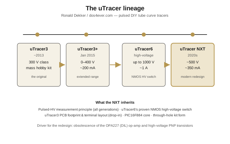
The uTracer NXT — Dekker calls it the “NXTracer” internally, short for Next Tracer — is Ronald Dekker’s ground-up redesign of his long-running DIY pulsed tube curve tracer, published on the build log at dos4ever.com/uTracerlogNXT. It keeps the idea that made every uTracer distinctive — pulse the high voltage into the tube for about a millisecond instead of holding it there continuously — but rebuilds the electronics around modern, still-available parts, folds in the proven high-voltage switch from the uTracer6, and stays a through-hole hobby kit that drops onto the original uTracer3 board footprint.
It is explicitly not an incremental patch of the uTracer3+. Dekker describes it as a “completely new design” and a “more modern and future-proof overhaul” of the whole circuit. And the trigger was not a new performance target — it was component obsolescence. Two parts the earlier designs depended on went out of production, and rather than paper over the gaps Dekker rebuilt the instrument. The NXT is the result, and it replaces the uTracer3+ as the mainstream model — the everyday tracer for the tubes most people actually test.
1.2 Why a curve tracer at all, and why pulsed
A tube curve tracer sweeps a set of controlled voltages onto a valve — plate (anode), screen grid, control-grid bias, and heater — and records the resulting anode and screen currents. The output is the family of I–V curves you find in a datasheet, plus the derived parameters (transconductance gm, amplification factor μ, plate resistance rp). You use it to match tubes, grade used stock, and generate SPICE models for amplifier simulation.
The obvious way to build one is a bench full of hefty regulated HV supplies, big heatsinks, and fans, because a power tube at a few hundred volts and a few hundred milliamps dissipates real wattage continuously. Dekker’s founding insight — the thing that made the original uTracer tiny and cheap — was to avoid all of that. Instead of holding the plate at, say, 300 V forever, the uTracer charges a pair of reservoir capacitors to the target voltage, connects them to the tube for only about 1 ms, samples the current at the end of that window, and disconnects. Average power stays trivially small even though the instantaneous operating point is a real, fully-loaded one. That is why a uTracer needs no transformer bank, no heatsinks, and runs from a laptop brick.
This pulsed principle is the through-line across every generation, and it is worth stating precisely because it is easy to get wrong: the ~1 ms measurement pulse has been standard since the very first uTracer. The original summary log describes “pulses of about a millisecond,” and the NXT log describes “a 1 ms measurement pulse in which the currents are measured.” The NXT did not shorten or lengthen that window. The only microsecond-scale timing anywhere in the design belongs to the boost-converter switching pulse — a completely different thing, the DC-DC converter’s own switching period, which was widened from 24 µs on the uTracer3 to 29 µs on the NXT to reach the higher reservoir voltages. Vol 3 works through the physics of the 1 ms measurement window and why capacitor droop has to be compensated during it.
1.3 The lineage, generation by generation
Dekker has been at this for over a decade. First ideas for a pulsed tube curve tracer date to around Christmas 2010; the first uTracer3 kits shipped around 2012. By the time the NXT arrived, roughly 2,600 uTracers of all kinds were in service across 63 countries over about 12 years — a large, engaged user base whose accumulated wish-list became a secondary motivation for the redesign.
1.3.1 uTracer3 / uTracer3+
This is the one that made the design famous — the mass-adopted hobby kit, sold in the thousands across dozens of countries over more than a decade. The original V3 covered roughly the 0–300 V region; the uTracer3+ later extended the anode/screen range to 0–400 V — the figure the primary log confirms for that generation. In everyday use it handles a few hundred milliamps of anode/screen current with modest grid-bias and heater supplies, talks to a PC over a serial link, and lives on a single compact through-hole board.
For the great majority of receiving tubes — preamp triodes, small-signal pentodes, common output tubes at sane operating points — the uTracer3+ is entirely sufficient. That is exactly Dekker’s argument: most of the interesting tube parameters are well characterized between 0 and 400 V. The 3+ became the reference point for “enough tracer for normal work,” and it is the model the NXT directly succeeds.
1.3.2 uTracer6
The “6” answered the one thing the 3+ could not do: big RF transmitter tubes and high-voltage audio finals — the class typified by a tube like the 6146B. Its envelope pushed anode/screen up to ~1000 V and currents up to ~1 A. Getting there forced two hard problems to be solved: cleanly generating a full kilovolt, and cleanly switching it.
The switching problem is the one that matters most for the NXT. Earlier uTracers switched the reservoir onto the tube with a high-voltage PNP bipolar stage — the fragile part of the design. In the uTracer6, Dekker replaced it with a robust NMOS high-voltage switch built around the IPD70R360P7 (a 700 V N-channel MOSFET) and a push-pull gate driver. That switch proved extremely durable in the field: across roughly 450 uTracer6 units in service, Dekker reports no switch failures to date. That field record is precisely why the same switch was carried straight into the NXT. The uTracer6 remains the specialist high-voltage tool in the family.
1.3.3 The stillborn 4 and 5
For completeness: uTracer4 and uTracer5 were intermediate concepts that never shipped — Dekker’s own word is “stillborn.” The line jumps from the 3+ to the 6 to the NXT in practice, and nothing in the NXT depends on the 4 or 5.
1.3.4 uTracer NXT
The NXT is neither “a 3+ with more voltage” nor “a 6 made cheaper.” It is a modernization, and the trigger was parts obsolescence rather than a new performance target — the subject of the next section. It targets the uTracer3+‘s voltage class, not the uTracer6’s kilovolt territory, and it carries the 6’s proven NMOS switch down into that mainstream envelope. It stays deliberately through-hole so hobbyists can still build it by hand, and it drops onto the uTracer3 PCB footprint as a near drop-in replacement.
1.4 Dekker’s motivation: component obsolescence
The stated primary driver was not a feature. It was that two families of parts the earlier designs leaned on were disappearing.
1.4.1 The OPA227 problem
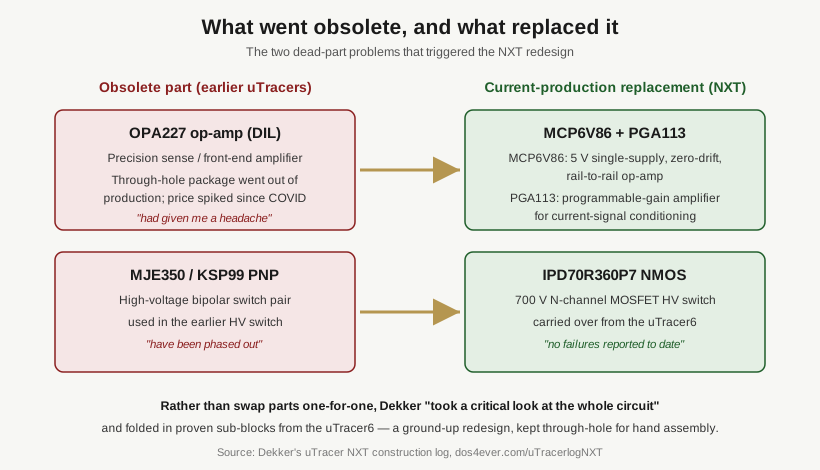
The OPA227 precision op-amp, in its through-hole DIL package, went out of production. Dekker records that its availability had “given me a headache” since the COVID-era supply crunch and that its price had “skyrocketed.” For a kit sold by one person at a fixed price, a single scarce, expensive, soon-to-be-unobtainable op-amp in the signal path is an existential problem — you cannot keep shipping kits around a part you cannot reliably buy.
Dekker had already prototyped a stopgap: a tiny adaptor board that drops a modern MCP6V86 zero-drift op-amp (a 5 V single-supply, rail-to-rail part) into the OPA227’s socket. In the NXT that fix is folded in properly, and the front-end current-measurement path is reorganized around a PGA113 programmable-gain amplifier feeding the MCP6V86 stages. The part-by-part electronics live in Vol 2; the point here is that a dead op-amp, not a wish for more range, started the project.
1.4.2 The high-voltage PNP problem
The second casualty was the high-voltage switch. The MJE350 and KSP99 high-voltage PNP transistors used in the earlier HV switch “in the meantime have been phased out.” That left the fragile part of the old design — the HV switch — built around parts that were also going away.
Here the fix and the improvement point in the same direction. The uTracer6 had already replaced that PNP-bipolar switch with the far more robust IPD70R360P7 NMOS switch, and had proven it across ~450 field units with no reported failures. So the obsolescence of the PNP parts was not a loss to be mourned — it was the occasion to bring the 6’s better, still-in-production switch down into the mainstream instrument.
1.4.3 From part-swap to redesign
Faced with two dead-part problems, Dekker could have shipped two adaptor boards and called it done. Instead, in his words, he “took a critical look at the whole circuit” and folded in proven sub-blocks from the newer uTracer6. The result is described as a completely new design rather than a revision — new front end, new switch, a rationalized rail scheme — while keeping the two constraints that define the product: it stays through-hole so hobbyists can hand-build it, and it stays on the uTracer3 board footprint so it slots into existing enclosures and terminal layouts.
There was also a secondary, non-obsolescence motivation worth naming: twelve years and 2,600-plus units generate a long user wish-list, and the ground-up redesign was the moment to fold in accumulated requests. But obsolescence is the headline; the wish-list is a rider.
1.5 What problem the NXT actually solves
Three things, concretely:
- Longevity of the design. By replacing the obsolete OPA227 and the phased-out HV PNP transistors with current-production devices — the MCP6V86 sense amplifier, the PGA113 programmable-gain stage, and the IPD70R360P7 NMOS high-voltage switch — the NXT can keep being sold and built for years without a scavenger hunt for dead parts. The PIC16F884 microcontroller was chosen in the same spirit: it is still listed as “recommended for automotive,” which Dekker reads as a promise that “it will be around for some time.” Longevity is a design goal here, not an accident.
- Bringing the 6’s robustness down to the mainstream instrument. The NMOS high-voltage switch that survived ~450 field uTracer6s with no failures is carried into the NXT, so the everyday ~450–500 V-class tracer inherits the reliability advance that had previously lived only in the kilovolt model.
- A cleaner, more modern analog platform. The redesign reorganizes the front end around the PGA113 for programmable range handling and rationalizes the supply rails around a single low-voltage logic rail plus a boost-generated −105 V rail (used both for the grid drive and for true-ground referencing of the sense amplifiers). It modernizes resolution and range handling without abandoning the parts-on-a-through-hole-board ethos.
1.6 Where the NXT sits in the envelope
This is the claim most worth getting right, because it is the one most easily overstated. The NXT lives deliberately in the uTracer3+ voltage class, not the uTracer6’s:
- Anode/screen voltage: 450 V default, with a 500 V option that requires higher-voltage-rated reservoir capacitors. The reservoir itself is 2 × 100 µF.
- Anode/screen current: 350 mA default, set by a 14.3 Ω sense resistor. The NMOS high-voltage switch itself is good for up to 1 A, so there is headroom above the default trip.
- Grid bias: 0 to −100 V default, extended to roughly −140 V in later development.
- Heater/filament: a ~1.2 kHz PWM supply, usable as DC or (via a transformer) AC for directly-heated tubes.
Put together, that is a ~450–500 V / few-hundred-mA instrument — squarely the 3+‘s band, and by design not the 6’s kilovolt, one-amp territory. The NXT is the successor to the popular tracer, not a replacement for the specialist one. If you need to push a 6146B or an 811A to a kilovolt, that is still a uTracer6 job (Vol 5 lays the three side by side and says when to reach for which). For everything from a 12AX7 to an EL34 at ordinary operating points, the NXT is the tool, and Dekker’s framing is that most tubes people actually test are comfortably characterized inside that window.
1.7 Who built it, and where the record lives
The whole uTracer line is one designer’s work: Ronald Dekker, publishing at dos4ever.com. That matters for how you read the sources. There is no marketing department and no glossy spec sheet — the primary record is a build log, an engineer’s running journal of decisions, dead ends, and measurements. The uTracer3+ and uTracer6 logs are mature and have matching printed construction manuals because thousands of those kits are in the field; the NXT log is still being written as the design settles.
So the authoritative NXT source is the NXT build log itself, cross-checked against the uTracer3 and uTracer6 logs for the baseline this dive compares against, plus an independent build review (tonymckenzie.com, 2026) for a second pair of eyes on the kit as delivered. The kit is a DIY through-hole build sold at €239 (€255 via PayPal) including worldwide shipping, supplied with all components, a programmed PIC, the PCB, and an extensive printed construction manual — tube sockets, selector switches, and the power cord are not included. Sales opened around 2026 with a substantial waiting list; Jeff’s unit is on that list, on order.
1.8 A note on documentation maturity
The NXT is genuinely newer and less documented than the 3+ and the 6. The build log is an evolving engineering journal, not a finished manual, and several downstream details — the exact host-software (uTracer-NXT-Gui) feature set, the data-export format, and the SPICE-model workflow for the NXT specifically — are not yet fully published. Where a fact isn’t confirmable from the log, this dive says so rather than inventing a number. The hardware architecture and measurement theory, by contrast, are well covered, and that is where Vol 2 (the design blocks and the part-by-part swaps) and Vol 3 (the pulsed-measurement physics) go next.