uTracer NXT · Volume 4
uTracer NXT — Vol 4: Building the Kit & Host Software
Assembly overview, calibration, the GUI, and data output
The NXT is the current mainstream uTracer — the ground-up redesign that replaces the uTracer3+, built around current-production parts after the OPA227 op-amp and the MJE350/KSP99 high-voltage PNP transistors were phased out (Vol 1). It stays in the uTracer3+‘s voltage class — 450 V default, 500 V option, 350 mA default anode/screen current, with the high-voltage switch itself good to about 1 A — and deliberately does not reach for the uTracer6’s kilovolt territory (Vol 5). This volume is the part a builder actually lives through: what shows up in the box, the order the board goes together, how the thing is calibrated once, what the PC-side application does, and what comes out the far end.
4.1 What arrives in the box
The NXT ships the way every uTracer has: as a DIY through-hole kit, not a finished cased instrument. The order (currently EUR 239, or EUR 255 paid via PayPal, with worldwide National Post shipping included) contains all the components, a PCB laid out on the uTracer3 footprint, a pre-programmed PIC16F884 microcontroller, and an extensive printed construction manual. It is meant to be hand-soldered at a bench with an iron.
“Through-hole” is the deliberate, buildability-preserving choice carried over from the earlier kits, but it is not literally 100 % through-hole: a handful of small-outline parts — the op-amps and the DAC — are surface-mount, either pre-placed or hand-soldered by the builder. Everything else is leaded and forgiving.
A few things are explicitly not in the kit and have to be supplied by the builder:
- Tube sockets and the socket wiring/adapters for whatever valves you intend to test.
- Selector switches for routing pins if you build a switched socket panel.
- A power cord / mains lead for whatever external supply you use.
- An enclosure. You case it yourself.
- The external low-voltage DC supply that powers the whole instrument — a laptop-brick-class supply, following uTracer tradition; the exact voltage is set by the kit documentation, and keeping the instrument on a small external brick (no internal mains transformer) is a big part of why it stays small and cheap. (Bench-confirm the exact supply spec against the shipped manual once the kit is in hand.)
Because the board is dimensioned to the uTracer3 footprint and terminal layout, a builder coming from a 3+ will find the mechanical layout familiar; the redesign is in the silicon and the firmware, not the outline.
Availability. Sales started around 2026 with a substantial waiting list; kits are reserved via a link on the dos4ever site. Jeff’s unit is on order, so the numbers in this volume are the documented kit figures ahead of the build; per-unit build notes land in MY_GEAR once it is in hand.
4.2 Assembly overview
The build order mirrors the earlier kits and follows the natural signal-chain grouping (Vol 2): get the low-voltage rail up first, populate the analog front end, then the high-voltage generation and switch, and verify serial communication before any high voltage is ever generated.
4.2.1 Low-voltage / power section first
Fit the +5 V logic regulator (IC1) and confirm the logic rail before anything else goes in — the PIC, the DAC, and the PGA all hang off it. This is exactly the stage the independent build review flagged: a single solder error on IC1’s left pin killed the +5 V supply and cost debugging time until it was found. The reviewer still rated the kit as “not that difficult to build” (9/10) — the lesson is that the +5 V rail is the first thing to meter, not the last. Confirm the small boost converter that generates the -105 V negative rail comes up as well; that rail does the true-ground referencing for the front end and the grid amplifier.
4.2.2 Passives, then the analog front end
Populate the sense resistors — the 14.3 ohm shunts that set the 350 mA default full-scale current — then the MCP6V86 single-supply rail-to-rail op-amps (the parts that replace the obsolete OPA227) and the PGA113 programmable-gain amplifier that conditions the current signal.
Follow the printed manual’s front-end decoupling placement exactly rather than second-guessing it: a precision programmable-gain stage like the PGA113 is sensitive to supply noise, so populate the bypass/decoupling parts where the manual calls for them. (The specific bypass values and placement are a bench-confirm against the shipped construction manual once the kit is in hand.)
4.2.3 High-voltage generation
Fit the boost inductors — mounted vertically on modified pin-header stubs rather than lying flat, per the log, for board fit and easier soldering — along with the boost NMOS, the rectifier diodes, and the two 100 uF reservoir capacitors that store the pulse energy. The reservoirs are 450 V-range parts in the default build; 500 V operation is conditional on fitting higher-voltage-rated reservoir caps, which can be a longer-lead-time part.
On the high-voltage side, the DC-DC boost that charges those reservoirs runs a slightly wider switching pulse than the 3 did — 24 us on the uTracer3, raised to 29 us on the NXT — to reach the higher target voltage. That microsecond figure is the converter switching pulse and has nothing to do with how long high voltage is applied to the tube; the tube itself sees a ~1 ms measurement pulse, which is the standard uTracer measurement window across the whole family (Vol 3).
4.2.4 High-voltage switch and grid amplifier
Fit the 700 V IPD70R360P7 NMOS high-voltage switch — the part carried straight over from the uTracer6, where across ~450 units in the field it has shown no reported failures — and the grid-bias chain: the 12-bit MCP4921 DAC (0-5 V) referenced by the LM4040C25 2.5 V reference, amplified by the OPA455 high-voltage op-amp in a -20x inverting stage to produce the -100 V grid range.
4.2.5 Re-ranging without a board respin
The board carries jumper and resistor options that let the builder re-range current, voltage, and grid bias without a PCB change. The default numbers — 450 V, 350 mA, grid 0 to -100 V — are the shipped configuration; the grid range in particular was extended to about -140 V in later development, and that kind of change is made by the option jumpers plus the calibration entries (below), not by cutting traces.
4.2.6 Firmware and serial bring-up
The PIC arrives pre-programmed, so there is no separate flashing step. Before you do anything with high voltage, verify communication over the serial link (9600 baud, 8-N-1) with the host — a clean command/response round-trip proves the +5 V rail, the PIC, and the FTDI path are all healthy, and it is the right gate to pass before you let the boost converters charge the reservoirs.
4.2.7 Bench discipline during the build
The reservoir capacitors store real energy: two 100 uF caps charged to 450-500 V hold on the order of 11-12 J (E is about 0.5 * C * V^2). That is a lethal stored-energy hazard, and it does not go away the instant you cut power. Standard uTracer/HV practice applies throughout and is written into this project’s bench notes:
- Verify the bleeder has actually done its job before opening the unit or touching the board — meter the reservoirs down to a safe voltage; don’t assume.
- Treat the tube socket as live during a sweep.
- Keep one hand off, and never probe under power.
4.3 Calibration
The NXT measures by digitizing small voltages across real resistors and amplifiers, so it must be calibrated once per build so the host can convert raw ADC counts into accurate volts and milliamps. This is a software-driven procedure, and it is one of the places the shipped kit’s specifics are still worth bench-confirming against the manual once Jeff’s unit is built; the shape below follows the construction log and the established uTracer calibration philosophy.
Two things the build review makes concrete and easy to miss: calibration needs test lamps (incandescent lamps used as known loads), and those aren’t obviously called out up front — have them on hand before you start.
4.3.1 Two tiers of user interface
- Slider (“novice”) mode — each channel has a calibration multiplier you nudge over a narrow range (roughly 0.9-1.1) until a known setpoint reads correctly.
- Direct (“expert”) mode — you type the actual measured resistor/divider values so the host uses the true hardware constants. This is also how you tell the software about any range-extension mods you fitted (e.g. the extended grid range), since a re-ranged channel needs its real constants entered rather than a slider nudge.
4.3.2 The grid channel gets the most attention
The grid channel has to stay accurate from -100 V all the way down to a fraction of a volt, so it gets a small multi-point procedure rather than a single trim:
- Null the amplifier’s offset first (adding a small correction resistor if the offset sits the wrong side of zero).
- Set the slope using a large bias point (e.g. -50 V).
- Trim the offset term using a very small bias point (a couple hundred millivolts).
The target is roughly <1 % error over -100 V to -1 V. The heater/filament channel is calibrated against its PWM duty-cycle-to-voltage relationship — the output voltage tracks the square root of the PWM duty setting (the PWM runs at about 1.2 kHz), so the host stores that curve rather than a single scale factor.
Calibration constants are stored by the host and reloaded on restart, so it is a one-time exercise per build — redone only if you re-range the hardware.
4.4 The host software / GUI
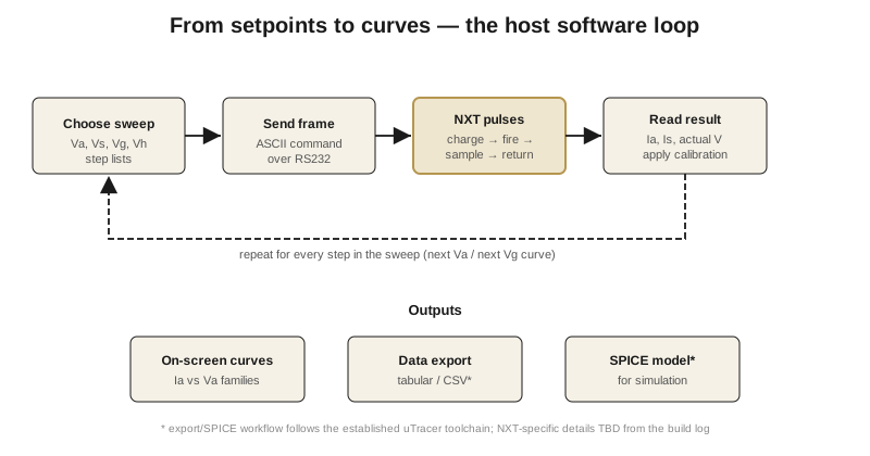
The PC-side application is where you actually operate the instrument (Vol 5 walks a full session). The NXT’s host is uTracer-NXT-Gui, a Windows PC application, and it continues the uTracer-series host lineage. From the family precedent and the NXT documentation, the GUI provides:
- Measurement-type selection — pick what to sweep and what to hold (e.g. sweep Va with Vg stepped between curves, heater held constant).
- Auto-gain — the software selects the PGA113 gain that best fits each measured point.
- Auto-averaging — the PIC’s 10-bit ADC can average from 1x to 32x per point to trade speed against noise.
- Compliance / current-limit setting, scaled to the selected current range, so a shorted or runaway tube aborts the pulse instead of stressing the hardware.
- A soft heater ramp — issuing a sequence of increasing heater setpoints rather than slamming a cold heater to full voltage.
- Live on-screen plotting of the curve family as points come back.
- The two-tier calibration form described above.
The exact export/plot feature list of the NXT GUI is not yet documented, so treat the finer feature details as bench-confirm once the shipped software is in hand rather than assuming feature-for-feature parity with any one earlier host.
4.5 The serial link
The host talks to the NXT over RS232 serial at 9600 baud, 8-N-1, using fixed-format ASCII command/response strings: 28 characters out (host command) and 38 characters back (instrument response). In practice you don’t wire a real RS232 port — you connect through an FTDI USB-serial cable, which presents a virtual COM port to the PC.
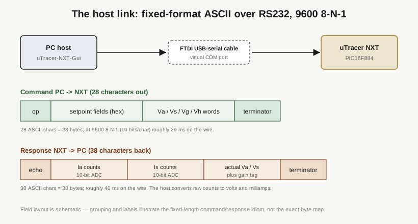
The fixed-length framing is what keeps the firmware simple: the PIC parses a known number of characters, executes one charge/pulse/sample cycle, and answers with a known-length string. At 9600 8-N-1 each character is 10 bits on the wire, so the 28-character command is on the order of 29 ms to transmit and the 38-character response about 40 ms — small compared with the reservoir charge time, and the reason the link speed has never needed to rise across the family. The host converts the returned raw ADC counts to volts and milliamps using the stored calibration constants.
4.6 Data output
The end product of a session is the curve family plus whatever you export for downstream use:
- On-screen curves — anode current Ia (and screen current Is) versus anode voltage Va, one trace per grid-bias setpoint, drawn live as points return.
- Tabular / data export — the uTracer toolchain exports the measured points for use in spreadsheets and plotting tools. The exact NXT export format/columns are not yet documented; treat the specifics as bench-confirm.
- SPICE models — generating simulate-able tube models from measured curves is a longstanding goal and workflow in the uTracer ecosystem. Whether and how the NXT host automates SPICE-model extraction specifically is not yet documented for the NXT, so don’t assume a one-click NXT SPICE exporter until the shipped software confirms it.
The honest summary: the NXT gives you live curves and exportable measured data; the finer export/SPICE details are the part of the toolchain that this dive will confirm at the bench once Jeff’s kit is built and running. Vol 5 picks up from a working, calibrated instrument and walks an actual measurement, then sets the NXT beside the uTracer3+ and uTracer6.