uTracer NXT · Volume 5
uTracer NXT — Vol 5: Using It + Generation Comparison
Operating workflow, an example measurement, and uTracer3+ / uTracer6 / NXT side by side
This volume is the operator’s half of the dive. Vols 1–4 covered what the NXT is, how the hardware is arranged, why the measurement is pulsed, and how the kit goes together. Here the concern is the loop you actually run at the bench — wire, ping, warm, sweep, read, export — followed by one worked example and the three-generation comparison the whole project was started to settle.
5.1 The operating loop
Running the NXT is a fixed rhythm: wire the tube, power and ping, ramp the heater, define the sweep, run the pulsed cycle, read and export. Each step below is where the machine’s character shows up.
5.1.1 Wiring the tube and getting the pinout right
Every measurement starts by landing the valve’s pins on the anode, screen, grid, cathode, and heater terminals of whatever socket is wired to the instrument. Tube sockets, selector switches, and the mains cord are not in the kit — that wiring is the builder’s own harness, so the pinout is on you. This is the one step with live-HV consequences: the anode and screen terminals will carry the charged-reservoir voltage during the pulse. Getting a pin swapped does not just spoil a curve, it can put 450 V where you did not mean it. Confirm the base diagram against the tube before anything is energized.
5.1.2 Power, connect, and ping
Apply the low-voltage supply brick, open the uTracer-NXT-Gui host application on the PC, and confirm the serial link before anything high-voltage is asked for. The physical link is RS232 at 9600 baud, 8-N-1, carried in practice over an FTDI USB-serial cable; the protocol is fixed-format ASCII — the host sends a 28-character command string and the instrument answers with 38 characters back. A “ping” round-trips one of those strings and returns the measured supply rails, which is the go/no-go that the board is alive and talking. No reservoir cap has been charged yet at this point.
5.1.3 Lighting the heater — ramp, don’t slam
Set the filament/heater voltage for the tube and let the software bring it up gradually rather than cold-slamming a room-temperature cathode. The heater is driven by PWM at 1.2 kHz, and it can be run DC for indirectly-heated tubes or, through an external transformer, AC for directly-heated types. A cold heater is a low-resistance load whose inrush stresses the filament; ramping it and then letting the cathode reach emitting temperature before you measure is what keeps early readings honest and the tube alive.
5.1.4 Defining the sweep
For a triode plate-curve family you tell the host to sweep anode voltage (Va) across a chosen range while it steps grid bias (Vg) between traces, holding the heater constant. The knobs that matter:
- Anode/screen voltage range. The reservoir caps can be charged to 450 V by default, or 500 V if the higher-rated reservoir capacitors are fitted. Two ~100 µF reservoirs supply the pulse.
- Current compliance. The default full-scale is 350 mA, set by the 14.3 Ω sense resistor; the NMOS HV switch itself has headroom to about 1 A. Set the compliance below what the tube (and the setpoint) should ever draw so a runaway or a wiring fault trips the measurement instead of the tube.
- Grid range. 0 to −100 V covers the overwhelming majority of receiving and audio valves; a later circuit extension reaches roughly −140 V for the deeper-biased types. The grid is negative-only — for positive grid drive you are in uTracer6 territory (below).
- Averaging. The 10-bit ADC sampling is selectable 1× to 32×; more averaging trades time for a quieter reading on low-current points.
5.1.5 Running the pulsed cycle
Once you hit run, the NXT executes the pulsed measurement of Vol 3 for every point in the grid: the boost converters charge a reservoir cap to the target HV while the tube is held cut-off, the grid is then pulsed to the test bias for the ~1 ms measurement window during which the tube conducts, and the anode and screen currents are read as small voltage drops across the sense resistors. Samples taken before, during, and after the pulse let the firmware separate true tube current from the reservoir cap’s discharge droop. The cap is then bled and the sequence advances to the next Va/Vg point.
Two consequences fall out of that architecture and are worth internalizing before you watch the first sweep crawl across the screen:
- A full family is not instantaneous. Each point carries its own charge phase, so a dense Va sweep across several grid steps takes real seconds-to-minutes, not a live scope trace. It is unattended once launched.
- The tube stays cold. Because HV is on the tube only for ~1 ms per point, you can push a valve well past its continuous plate-dissipation rating during the pulse without cooking it — that is the entire reason the instrument is pulsed rather than a continuous supply.
One point that trips people who skim the timing spec: the ~1 ms is the measurement pulse into the tube, and it is the same ~1 ms across the whole uTracer family — the original uTracer, the 3+, the 6, and the NXT all measure in a roughly-millisecond window. The only microsecond figure anywhere in the design is the boost-converter switching pulse, which was lengthened from 24 µs on the uTracer3 to 29 µs on the NXT to reach the higher charge voltage. That is the DC-DC converter’s switching period, not how long HV sits on the tube. Do not conflate them.
5.1.6 Reading and exporting
When the family is complete the host plots the I–V curves and can derive tube parameters from
them. You inspect the fan of traces, read parameters at whatever operating point you care about
(next section), and export the measured points for archiving, external plotting, or
model-fitting. The exact export/plot feature set of the NXT GUI — column formats, whether it
drives SPICE-model extraction directly — is one of the items still to confirm against the
shipped software once Jeff’s kit is built and registered under MY_GEAR slug utracer-nxt.
5.2 A worked example measurement
Take a small indirectly-heated triode as the subject. The procedure — the numbers are an illustration of the method, not measured NXT data, since the kit is on order:
- Set the heater to the tube’s rated filament voltage and let the soft ramp bring the cathode up; wait for temperature to stabilize.
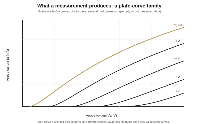
- Choose “Ia versus Va, Vg stepped.” Sweep Va from 0 to ~300 V — comfortably inside the 450 V envelope — while stepping Vg from 0 V to −8 V in 2 V increments (five traces).
- Set the current compliance to a safe value for this tube, well under the 350 mA full scale — for a small triode a few tens of mA is plenty of headroom.
- Run. The NXT fires the pulsed cycle at each of the five grid setpoints across the Va sweep and returns five plate curves that fan out exactly like the opening figure: at Vg = 0 V the tube conducts hard and the curve climbs steeply; each more-negative grid step shifts the curve right and flattens it.
From that family you read the classic small-signal parameters at any operating point:
- Transconductance gm — the vertical spacing between adjacent curves at a fixed Va, divided by the grid-step voltage (ΔIa/ΔVg). In the example, gm at a chosen Va is (Ia at Vg=−2 V minus Ia at Vg=−4 V) / 2 V.
- Amplification factor μ — from the horizontal spacing between curves at a fixed Ia: how much extra Va is needed to restore the same current after the grid is made 2 V more negative (ΔVa/ΔVg at constant Ia).
- Plate resistance rp — the local slope of one curve, ΔVa/ΔIa at a fixed Vg. The three are tied by μ = gm · rp, which is a useful sanity check on your reads.
Then export the points. Everything downstream — matched-pair selection, before/after readings on a suspect valve, feeding a SPICE model — works off that exported family.
5.3 Where the NXT sits versus the uTracer6
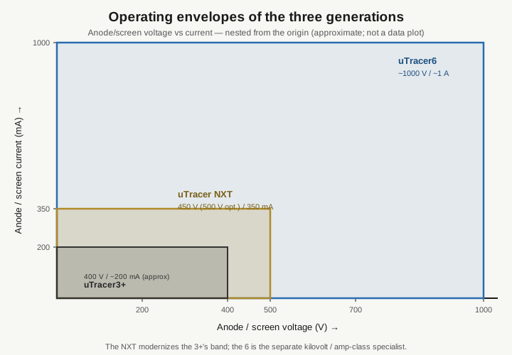
The NXT is the everyday, publishable-curve tracer: modern parts, robust, hand-solderable, living in the ~450–500 V / few-hundred-mA band that covers the overwhelming majority of receiving and audio valves. It is the current mainstream model and the direct replacement for the uTracer3+.
Reach for the uTracer6 instead only when a tube genuinely needs what the NXT deliberately does not do: kilovolt plate voltage (up to ~1000 V), an amp of current, or positive grid drive with grid-current measurement — the domain of sweep tubes, beam-power finals, and RF transmitter valves. The 6 is the specialist; the NXT is the workhorse. Full detail on the kilovolt machine is in the uTracer6 dive.
On Jeff’s bench the division of labor is: the quick go/no-go testers — the Heathkit TT-1 (dynamic Gm) and the Supreme 385 (emission) — handle triage, deciding whether a valve is worth bothering with; the curve tracers then produce the actual curves and models. Among the tracers, the NXT is the default and the 6 is pulled out for the high-voltage jobs.
5.4 uTracer3+ / uTracer6 / NXT side by side
This is the comparison the project set out to make. NXT figures are from the construction log
and are firm; cells marked with an asterisk (*) are build-log values for the earlier
generations that should be re-verified against the uTracer3/uTracer6 documentation before you
rely on the last digit.
Table 1 — uTracer3+ / uTracer6 / NXT side by side
| Aspect | uTracer3+ | uTracer6 | uTracer NXT |
|---|---|---|---|
| Positioning | Mass-adopted hobby tracer | High-voltage / RF-tube specialist | Modern redesign of the mainstream tracer |
| Status | Superseded by the NXT | Current specialist model | Current mainstream model |
| Max anode/screen voltage | 400 V | ~1000 V (target) | 450 V default; 500 V option |
| Max anode/screen current | ~200 mA* | ~1 A | 350 mA default (HV switch good to ~1 A) |
| Reservoir caps | reservoir-cap pulse* | reservoir-cap pulse* | 2 × 100 µF, 450 V range |
| Grid bias range | 0 to −50 V* | 0 to −100 V; +optional 0 to +100 V & grid-current* | 0 to −100 V; extended ~−140 V |
| Measurement pulse into tube | ~1 ms | ~1 ms | ~1 ms |
| Boost-converter switching pulse | 24 µs* | —* | 29 µs |
| HV switch device | HV PNP bipolar (MJE350 / KSP99) | NMOS, 700 V IPD70R360P7 | NMOS, 700 V IPD70R360P7 (carried over from the 6) |
| Current-sense front end | OPA227-based* | (see the uTracer6 dive)* | PGA113 PGA + MCP6V86 zero-drift op-amps |
| Sense resistor | —* | —* | 14.3 Ω (sets 350 mA full scale) |
| Grid-bias DAC | —* | —* | 12-bit MCP4921 + OPA455 −20× HV stage |
| Voltage reference | —* | —* | LM4040C25, 2.5 V |
| Microcontroller | earlier PIC* | earlier PIC* | PIC16F884 (chosen for longevity) |
| ADC | 10-bit* | 10-bit* | 10-bit, 1×–32× averaging (PGA-ranged) |
| Negative supply rail | —* | —* | −105 V (boost-generated) |
| Heater supply | PWM, DC/AC* | PWM, DC/AC* | PWM at 1.2 kHz, DC or AC |
| Host link | RS232 via USB adapter | RS232 via USB adapter | RS232, 9600 8-N-1, FTDI cable |
| Host software | uTracer3 GUI* | uTracer6 GUI* | uTracer-NXT-Gui |
| Kit form / board | through-hole kit | through-hole kit | through-hole kit on the uTracer3 footprint (drop-in) |
| Price | — | — | €239 (€255 via PayPal) |
5.4.1 Reading the table — what actually changed in the NXT
Three things moved, and they are all downstream of one cause — component obsolescence. The redesign was forced by parts going out of production, not by a wish to chase higher voltage:
- The high-voltage switch went from PNP bipolar to NMOS. The old MJE350 / KSP99 HV PNP transistors were phased out, so the NXT carries over the uTracer6’s field-proven 700 V IPD70R360P7 NMOS switch — the same part proven in the 6. With ~450 uTracer6’s in the field reporting no NMOS failures to date, this is the reliability upgrade.
- The analog front end was rebuilt around current-production parts. The OPA227 op-amp went out of production and its price spiked; the front end is rebuilt around a PGA113 programmable-gain amplifier that conditions the current signal and feeds zero-drift MCP6V86 op-amps in place of the OPA227, which both dodges the obsolescence and gives cleaner, auto-ranged current reads. This was the reason the whole thing was redesigned.
- The power architecture was simplified. The old ±15 V auxiliary rails are gone, leaving a clean +5 V / −105 V scheme, with the negative rail also serving as the true-ground reference for the front end.
5.4.2 What deliberately did not change
Everything that made the uTracer worth cloning was kept:
- the pulsed, reservoir-cap ~1 ms measurement principle — identical in spirit across the whole family;
- the 10-bit ADC and averaging scheme;
- the PIC microcontroller core (an F884 chosen specifically for its long production lifetime);
- the RS232-over-USB host link and the PC-GUI-driven workflow;
- the through-hole, hand-solderable kit on the uTracer3 board footprint, so it drops into an existing uTracer3 chassis with minimal rework;
- and, critically, the ~450–500 V / few-hundred-mA envelope that keeps the NXT squarely in the popular-tracer band. It is not, and was never meant to be, a step toward the uTracer6’s kilovolt territory — the 6 already owns that ground.
5.5 Safety at the bench
The instrument charges two ~100 µF reservoir caps to 450–500 V. That is a lethal stored-energy hazard on the order of 11–12 J (≈ ½·C·V²) sitting on the board after power-down. Standard uTracer practice applies and is not optional: discharge the reservoir caps before touching the board, keep one hand off, and never probe under power. The socket terminals are live during the sweep. Treat it as a live-HV instrument every time, exactly as the shared bench-discipline notes require.
5.6 Open items to confirm once the kit is built
Because the NXT is the newest of the three and the least externally documented, a handful of
downstream particulars are flagged to nail down once Jeff’s unit is assembled and registered
under MY_GEAR slug utracer-nxt:
- the exact uTracer-NXT-Gui feature list and its CSV/export column format;
- whether the host automates SPICE-model extraction or hands off to an external tool;
- the shipped construction-manual revision and any errata;
- the last-digit precision on the envelope, the current trip point, and the values of the jumper/resistor options that re-range voltage, current, and grid bias.
The architecture and the pulsed-measurement theory (Vols 2–3) are well supported by the construction log; it is the shipped software and the as-built kit particulars that firm up after the build. Once the unit is in hand, this volume gets its illustrative example replaced with a real measured family and the FIGURE SLOTs above filled with photographs of Jeff’s own board.